ENGINE PERFORMANCE
2.4L
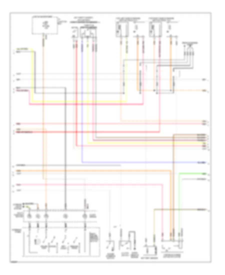
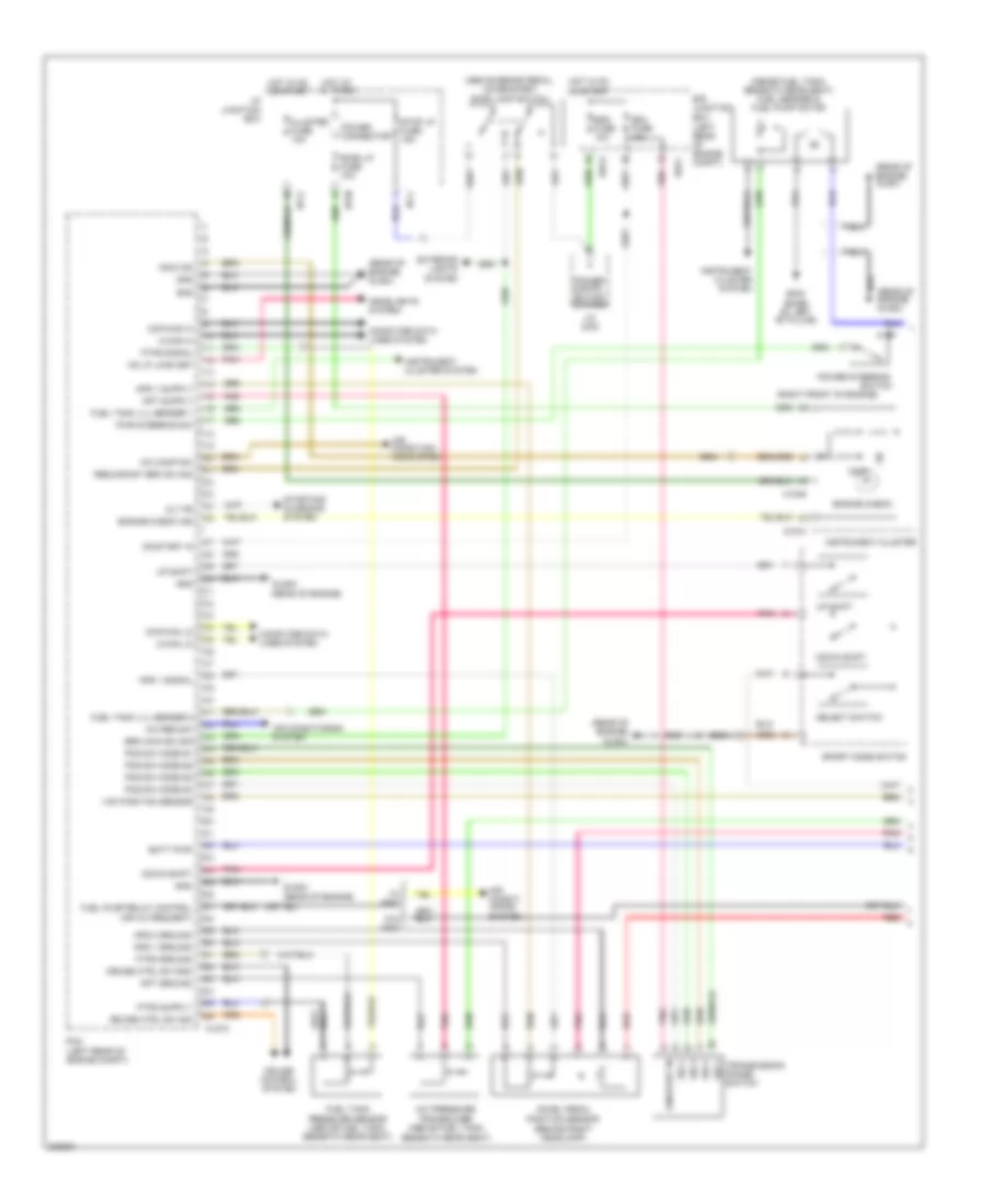
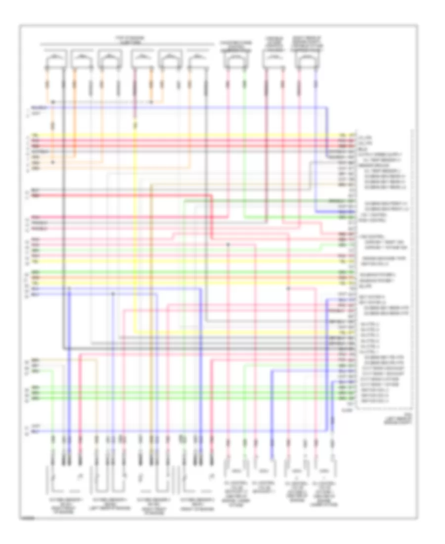
2.4L, Engine Performance Wiring Diagram (1 of 5) for Hyundai Santa Fe Limited 2010

List of elements for 2.4L, Engine Performance Wiring Diagram (1 of 5) for Hyundai Santa Fe Limited 2010:
- (or red)
- (rear of engine) ghg05
- 26_vfs
- 35r_vfs
- A/c comp sw
- A/c request sw
- Air conditioning system
- Alt fr
- Atm solenoid valve (top of transaxle)
- Back up lp rly ctrl
- Battery power
- Ccp-can high
- Ccp-can low
- Chg-a
- Clutch switch
- Computer data lines system
- Cruise ctrl sw gnd
- Cruise ctrl sw sig
- Down shift
- E/r junction box (left rear of engine compt)
- Ecu fuse 10a
- Ec_vfs
- Exterior lights system
- Ghg05 (rear of engine)
- Gnd
- Hot at all times
- Hot in on or start
- I/p junction box
- I/p-j
- Ign coil ctrl cyl 1
- Ign coil ctrl cyl 2
- Ign coil ctrl cyl 3
- Ign coil ctrl cyl 4
- Ign coil ctrl shield
- Input speed
- Input speed sig
- Lp_vfs
- M/t
- Main brake sw sig
- Od_vfs
- Oil temp sensor (+)
- Oil temp sensor (-)
- On/start input
- Output speed
- Output speed sig
- Pcm (left rear of engine compt)
- Pnk
- Position sw code s1
- Position sw code s2
- Position sw code s3
- Position sw code s4
- Power steering sw
- Red
- Redundant brake sw
- Select sw
- Select switch
- Sensor oil temperature
- Shift interlock system
- Shift lock solenoid
- Signal 1
- Signal 2
- Signal 3
- Signal 4
- Solenoid power 1
- Solenoid power 2
- Sport mode switch
- Ss_a
- Ss_b
- Start relay
- Starting/charging system
- Stop lamp fuse 15a
- Stop lamp switch
- Tcu fuse 15a
- Transaxle range switch (on top of transaxle)
- U/h-c
- U/h-u
- Ud_vfs
- Up shift
- Vcm motor output 1
- Vcm motor output 2
- W/ immo
- W/o immo
- Wiper "p" input
- Wiper/washer system
2.4L, Engine Performance Wiring Diagram (2 of 5) for Hyundai Santa Fe Limited 2010
List of elements for 2.4L, Engine Performance Wiring Diagram (2 of 5) for Hyundai Santa Fe Limited 2010:
- (+)
- (-)
- (on throttle body)
- (or red)
- (rear of engine)
- (rear of engine) ghg04
- (top left side of engine) ignition coils 2 & 4
- (top right side of engine) ignition coils 1 & 3
- Battery sensor
- Cancel
- Clock spring
- Clutch switch
- Cruise main
- Esc sw fuse 10a
- Etc motor & throttle position sensor
- Ghg02
- Hot in on or start
- I/p junction box
- I/p-m
- Illum
- Interior lights system
- Lin line
- M/t
- M02-r
- Motor
- Multi- function switch
- Nca
- Pnk
- Power steering switch
- Red
- Resume/ accel
- Right cruise remote control switch
- Set/ coast
- Snsr +
- Steering wheel
- Throttle position sensor
- Variable charge motion actuator
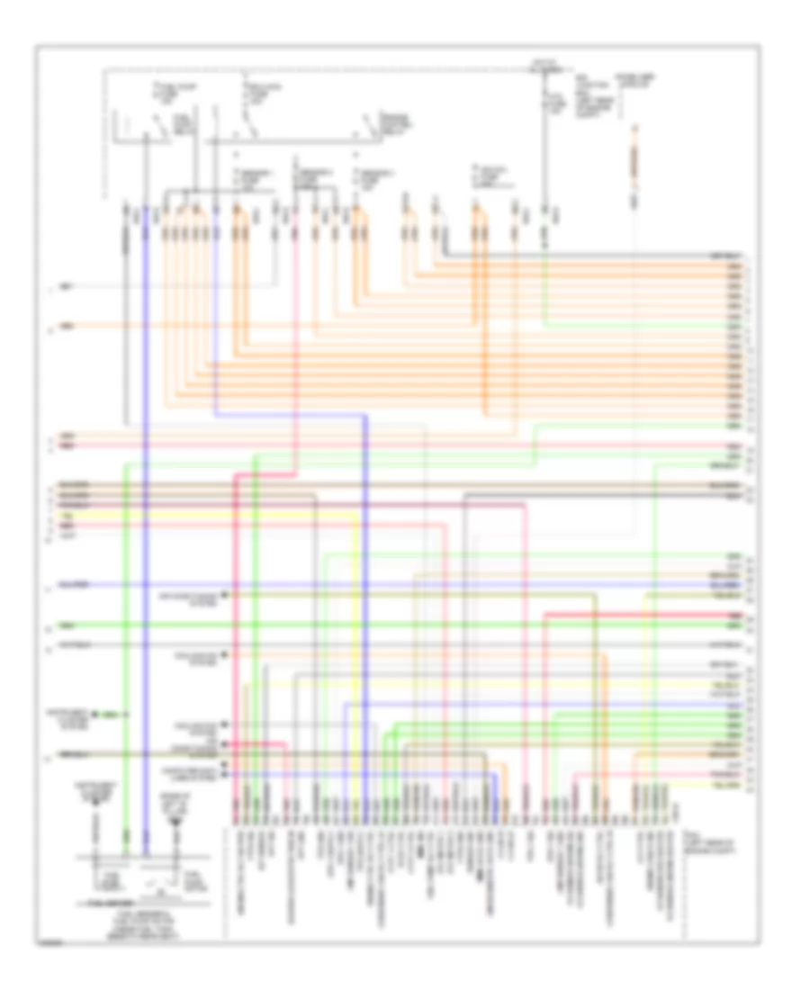
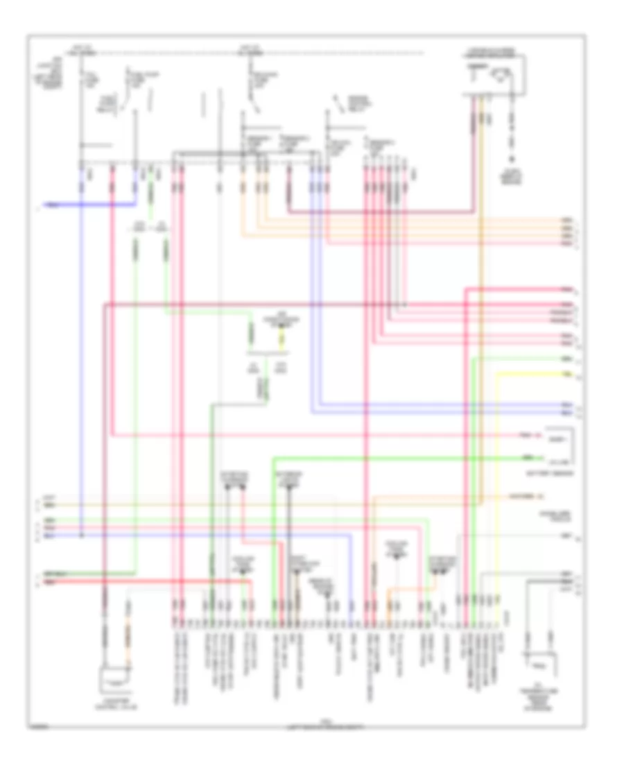
2.4L, Engine Performance Wiring Diagram (3 of 5) for Hyundai Santa Fe Limited 2010
List of elements for 2.4L, Engine Performance Wiring Diagram (3 of 5) for Hyundai Santa Fe Limited 2010:
- (base of left "b " pillar) gf05
- A/con rly ctrl
- Air conditioning system
- Aps 1 gnd
- Aps 1 sig
- Apt gnd
- Apt sig
- Atm fuse 15a
- Blower load detection in
- C-can hi
- C-can lo
- Ccv ctrl
- Chg-k
- Cmp sensor 1 gnd
- Cmp sensor 1 sig
- Computer data lines system
- Condenser fan rly ctrl hi
- Condenser fan rly ctrl lo
- Cooling fan system
- Cooling fan system air conditioning system
- Cvvt 1 ctrl
- Cvvt 2 ctrl
- E/r junction box (left rear of engine compt)
- Ecu main fuse 40a
- Engine check ind
- Engine control relay
- Engine ctrl rly ctrl
- Engine ctrl rly on pwr
- Etc motor 1
- Etc motor 2
- Ftps gnd
- Ftps sig
- Fuel level
- Fuel pump motor
- Fuel pump fuse 15a
- Fuel pump relay
- Fuel pump rly ctrl
- Fuel sender
- Fuel sender & fuel pump motor (inside fuel tank, beneath rear seat)
- Hot at all times
- Iat sensor
- Ign coil fuse 20a
- Immo data line
- Immo ind
- Immobilizer module
- Instrument cluster system
- Lin/diagnostic data line
- O2 sensor (down) gnd
- O2 sensor (down) heater
- O2 sensor (down) sig
- O2 sensor (up) heater
- Pcm (left rear of engine compt)
- Pcsv ctrl
- Pnk
- Red
- Sensor 1 fuse 10a
- Sensor 2 fuse 15a
- Sensor 3 fuse 15a
- Sensor gnd
- Tps 1 sig
- Tps gnd
- U/h-c
- U/h-u
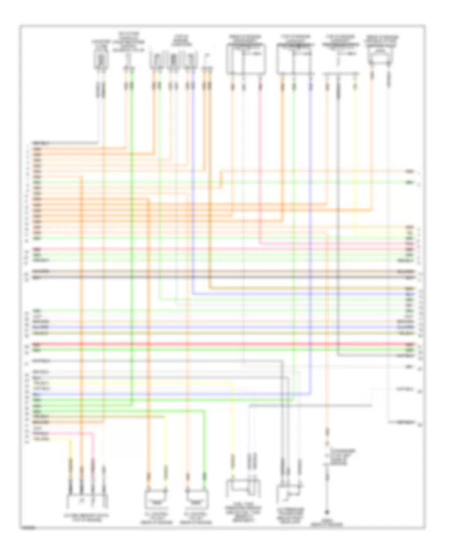
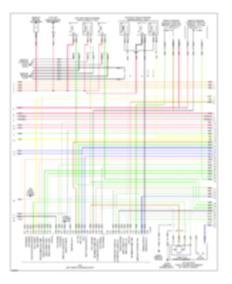
2.4L, Engine Performance Wiring Diagram (4 of 5) for Hyundai Santa Fe Limited 2010
List of elements for 2.4L, Engine Performance Wiring Diagram (4 of 5) for Hyundai Santa Fe Limited 2010:
- (on intake manifold) canister purge control solenoid valve
- (rear of engine)
- (rear of engine) crankshaft position sensor
- (top of engine)
- (top of engine) camshaft position sensor 1
- (top of engine) camshaft position sensor 2
- (top of engine) injectors
- A/c pressure transducer (behind right headlamp)
- Canister close valve
- Condenser (top left side of engine)
- Fuel tank pressure sensor (above fuel tank, beneath rear seat)
- Ghg04 (rear of engine)
- Nca
- Oil control valve 1 (rear of engine)
- Oil control valve 2 (rear of engine)
- Oxygen sensor (down)
- Pnk
- Red
- Variable intake manifold valve
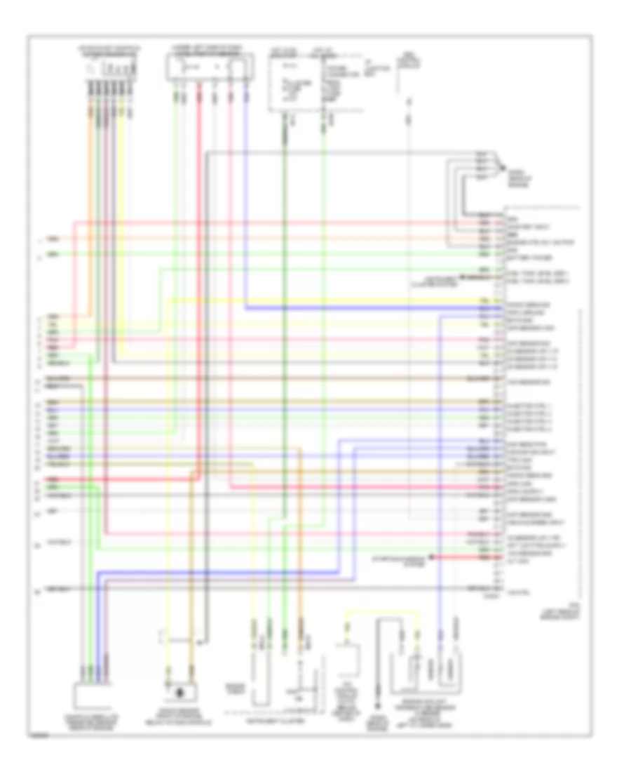
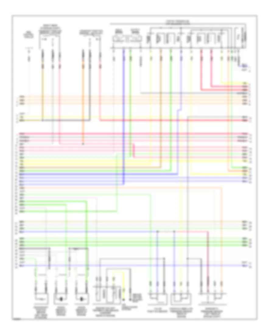
2.4L, Engine Performance Wiring Diagram (5 of 5) for Hyundai Santa Fe Limited 2010
List of elements for 2.4L, Engine Performance Wiring Diagram (5 of 5) for Hyundai Santa Fe Limited 2010:
- & sender
- (auto)
- (behind center of dash)
- (on exhaust manifold) oxygen sensor (up)
- (on rear of left cylinder head)
- (under left side of dash)
- A/c control module
- Accel position sensor
- Alt com
- Aps 2 ground
- Aps 2 sig
- Battery power
- Chg-k
- Ckp sensor gnd
- Ckp sensor sig
- Cluster fuse 10a
- Cmp sensor 2 gnd
- Cmp sensor 2 sig
- Ects gnd
- Ects sig
- Engine check
- Engine coolant temperature sensor
- Engine ctrl rly on pwr
- Engine)
- Esc control module
- Fuel tank level sdr 1
- Fuel tank level sdr 2
- Ghg04 (rear of
- Ghg04 (rear of engine)
- Gnd
- Gnd gnd
- Hot at all times
- Hot in on or start
- I/p junction box
- I/p-k
- I/p-m
- Immo
- Injector ctrl 1
- Injector ctrl 2
- Injector ctrl 3
- Injector ctrl 4
- Instrument cluster
- Instrument cluster system
- Knock sens gnd
- Knock sens sig
- Knock sensor (front of engine, below intake manifold)
- M15-a
- M15-b
- Maf/map sig input
- Manifold absolute pressure sensor (rear of engine)
- Map sens pwr
- Nca
- O2 sensor (up) v g
- O2 sensor (up) v ip
- O2 sensor (up) v n
- O2 sensor (up) v rc
- On/start input
- Pcm (left rear of engine compt)
- Pnk
- Power connector
- Red
- Room lamp fuse 10a
- Sender
- Sensor
- Starting/charging system
- Tps 2 sig
- Vcm sensor gnd
- Vcm sensor sig
- Vehicle speed input
- Vip
- Vis ctrl
- Vrc
3.5L
3.5L, Engine Performance Wiring Diagram (1 of 5) for Hyundai Santa Fe Limited 2010
List of elements for 3.5L, Engine Performance Wiring Diagram (1 of 5) for Hyundai Santa Fe Limited 2010:
- (above brake pedal, on bracket)
- (behind right headlamp)
- (inside fuel tank, beneath rear seat) fuel sender & fuel pump motor
- (left rear of engine compt)
- (rear of engine)
- (right front of engine)
- A/c comp sw
- A/c pressure transducer (above fuel tank, beneath rear seat)
- A/c req sw
- Accel pedal
- Air condit- ioning system
- Air condition- ing system
- Air conditioning system
- Alt fr
- Aps 1 ground
- Aps 1 signal
- Aps 2 ground
- Apt ground
- Batt pwr
- Brk main sw sig
- C-can hi
- C-can lo
- Ccp-can hi
- Ccp-can lo
- Clg-a
- Cluster fuse 10a
- Computer data lines system
- Cruise control system
- Cruise ctrl sw gnd
- Cruise ctrl sw sig
- Down shift
- E/r junction box
- Engine check
- Engine check ind
- Esc fuse 10a
- Esu fuse 10a
- Exterior lights system
- Ftps ground
- Ftps signal
- Fuel pump relay control (or a/c request)
- Fuel tank lvl sender 1
- Fuel tank lvl sender 2
- Fuel tank pressure sensor (above fuel tank, beneath rear seat)
- Gf05 (base of left "b" pillar)
- Glg01
- Glg02
- Glg04
- Gnd
- Hd lp load det
- Headlights system
- Hot at al times
- Hot in on or start
- I/p junction box
- I/p-j
- I/p-k
- I/p-m
- Immo
- Immo ind
- Instrument cluster
- Instrument cluster system
- J/c jc02
- M15-a
- M15-b
- On/start in
- Pcm
- Pnk
- Pos sw code s1
- Pos sw code s2
- Pos sw code s3
- Pos sw code s4
- Position sensor
- Power connector
- Power distri- bution system
- Power steering
- Pwr steering sw
- Red
- Redundant brk sw sig
- Room lp fuse 10a
- Select switch
- Sig 1
- Sig 2
- Sig 3
- Sig 4
- Sport mode switch
- Starting/ charging system
- Stop lamp switch
- Stop lp fuse 15a
- Switch
- Transmission range switch
- U/h-c
- U/h-u
- Up shift
- Vcm position sensor
- W/ immo
- W/o immo
3.5L, Engine Performance Wiring Diagram (2 of 5) for Hyundai Santa Fe Limited 2010
List of elements for 3.5L, Engine Performance Wiring Diagram (2 of 5) for Hyundai Santa Fe Limited 2010:
- (left rear of engine compt)
- (rear of
- (rear of engine)
- Air conditioning system
- Alt com
- Aps 2 signal
- Apt signal
- Batt pwr
- Battery sensor
- Canister control valve
- Ccv control
- Clg-a
- Clg-b
- Cooling fans system
- Crank requst
- E/r junction box (left rear of engine compt)
- Ecu main fuse 40a
- Engine control relay
- Engine ctrl rly "on" pwr
- Engine ctrl rly ctrl
- Engine ctrl rly on power
- Engine)
- Exterior lights system
- Fan rly ctrl lo
- Fuel pump fuse 15a
- Fuel pump relay
- Fuel pump rly ctrl
- Glg04
- Gnd
- Hot at all times
- Ign coil fuse 20a
- Immo data line
- Immobilizer
- Incamb/excambi pwr
- Input speed signal
- Lin line
- Lin/diagnostic data line
- Module
- Motor
- Od_vfs
- Oil temperature
- Output speed signal
- Pcm
- Pnk
- Red
- Select switch
- Sender
- Sensor (rear of engine)
- Sensor 1 fuse 10a
- Sensor 2 fuse 15a
- Sensor 3 fuse 15a
- Shift interlock system
- Shift lock solenoid
- Snsr +
- Start over running
- Start relay
- Starting/ charging system
- Tcu fuse 15a
- Tps sply
- U/h-c
- U/h-u
- Variable charge motion actuator
- Vcm motor output
- W/ immo
- W/o immo
3.5L, Engine Performance Wiring Diagram (3 of 5) for Hyundai Santa Fe Limited 2010
List of elements for 3.5L, Engine Performance Wiring Diagram (3 of 5) for Hyundai Santa Fe Limited 2010:
- (left rear of engine compt)
- (rear of
- (rear of engine)
- (rear of engine) camshaft position sensor 1 (intake)
- (rear of engine) camshaft position sensor 2 (exhaust)
- (rear of engine) condenser 1
- (rear of engine) glg04
- (rear of of engine compt) glg03
- (top left side of engine) condenser 2
- (top left side of engine) ignition coils 2, 4 & 6
- (top right side of engine) ignition coils 1, 3 & 5
- 35r_vfs
- Air condi- tioning system
- Blw load detection in
- Bps signal
- Ckps hi
- Ckps lo
- Clg-b
- Cmps bk 2 exhaust sig
- Cmps bk 2 intake sig
- Ec_vfs
- Engine compt)
- Etc motor & throttle position sensor (on throttle body)
- Etcs signal
- Glg03
- Glg04
- Ignition coil 1
- Ignition coil 3
- Incamb/excamb1 gnd
- Incamb/excamb2 gnd
- Intake (mifd) air temp
- Knock sens 1 high
- Knock sens 1 lo
- Knock sens 2 high
- Knock sens 2 lo
- Map signal
- Motor
- Nca
- O2 sens (bk1 front) hi
- O2 sens (bk1 front) lo
- O2 sens (bk2 rear) lo
- Ots ground
- Ots signal
- Pcm
- Pnk
- Shield ground
- Ss_a
- Throttle position sensor
- Tps 1 ground
- Tps 1 signal
- Tps 2 signal
- Vehicle speed input
- Vps signal
- Wiper "p" input
- Wiper/ washer system
3.5L, Engine Performance Wiring Diagram (4 of 5) for Hyundai Santa Fe Limited 2010
List of elements for 3.5L, Engine Performance Wiring Diagram (4 of 5) for Hyundai Santa Fe Limited 2010:
- (behind center of dash) gm03
- (left rear of engine compt)
- (rear of engine)
- (right rear
- (top of transaxle)
- 26 vfs
- 35r vfs
- Air conditioning system
- Atm solenoid valve
- Barometic pressure sensor
- Camshaft position sensor 1 (exhaust)
- Crankshaft position sensor (left rear of engine)
- Ec vfs
- Engine coolant temperature sensor & sender
- Esc control module
- Input speed
- Knock sensor 1 (rear of engine)
- Knock sensor 2 (rear of engine)
- Lp vfs
- Manifold absolute pressure sensor
- Nca
- Od vfs
- Of engine compt) camshaft position sensor 2 (intake)
- Oil temperature
- Output speed
- Pnk
- Red
- Sender
- Sensor
- Ss a
- Ss b
- Ud vfs
- Valve position sensor
3.5L, Engine Performance Wiring Diagram (5 of 5) for Hyundai Santa Fe Limited 2010
List of elements for 3.5L, Engine Performance Wiring Diagram (5 of 5) for Hyundai Santa Fe Limited 2010:
- engine)
- (b2/s1)
- (center of
- (front of engine)
- (right front of engine)
- (right rear of engine compt) variable intake manifold valve 1
- (top of engine)
- 26_vfs
- Canister purge control solenoid valve
- Clg-b
- Cmps bk 1 "ehst" sig
- Cmps bk 1 "intake" sig
- Cvvt bank 1 exhaust
- Cvvt bank 1 intake
- Cvvt bank 2 exhaust
- Cvvt bank 2 intake
- Ect motor hi
- Ect motor lo
- Engine, under
- Engine, under intake)
- Ignition coil 2
- Ignition coil 4
- Ignition coil 5
- Ignition coil 6
- Incamb 2/excamb1 pwr
- Inj ctrl 1
- Inj ctrl 2
- Inj ctrl 3
- Inj ctrl 4
- Inj ctrl 5
- Inj ctrl 6
- Injectors
- Intake)
- Lp_vfs
- Nca
- O2 sens (bk1 fr) htr
- O2 sens (bk1 rear) hi
- O2 sens (bk1 rear) htr
- O2 sens (bk1 rear) lo
- O2 sens (bk2 fr) htr
- O2 sens (bk2 front) hi
- O2 sens (bk2 front) lo
- O2 sens (bk2 rear) hi
- O2 sens (bk2 rear) htr
- Oil control valve (exhaust) 1
- Oil control valve (exhaust) 2
- Oil control valve (intake) 1
- Oil control valve (intake) 2 (center of
- Oil temp sensor (+)
- Oil temp sensor (-)
- Oxygen sensor 1 (b1/s1)
- Oxygen sensor 2
- Oxygen sensor 3 (b1/s2)
- Oxygen sensor 4 (b2/s2) (left rear of engine)
- Pcm (left rear of engine compt)
- Pcsv control
- Pnk
- Red
- Sensor ground
- Solenoid power 1
- Solenoid power 2
- Ss_b
- Ud_vfs
- Variable intake manifold valve 2
- Vis 1 control
- Vis2 control