ENGINE PERFORMANCE
2.0L
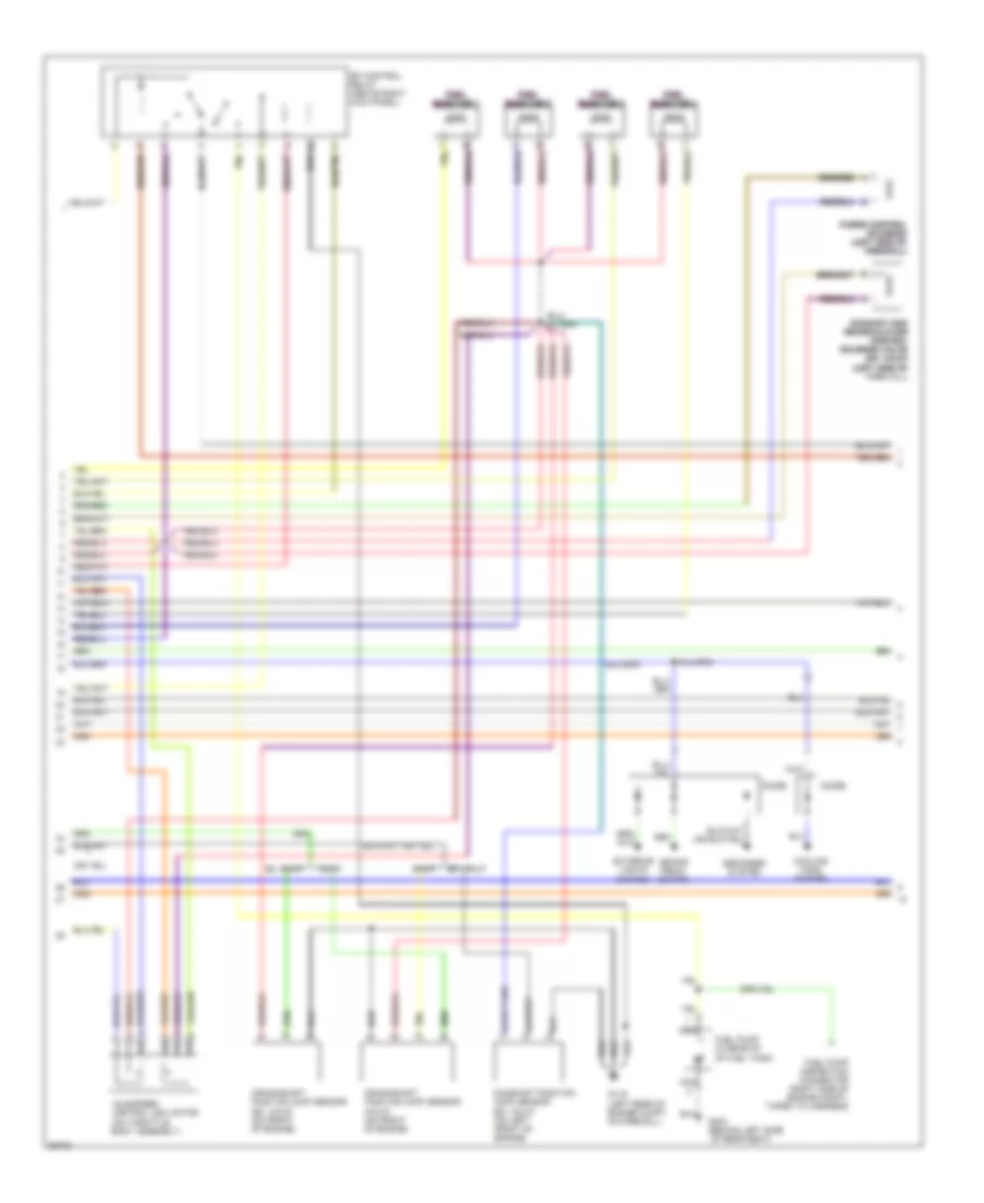
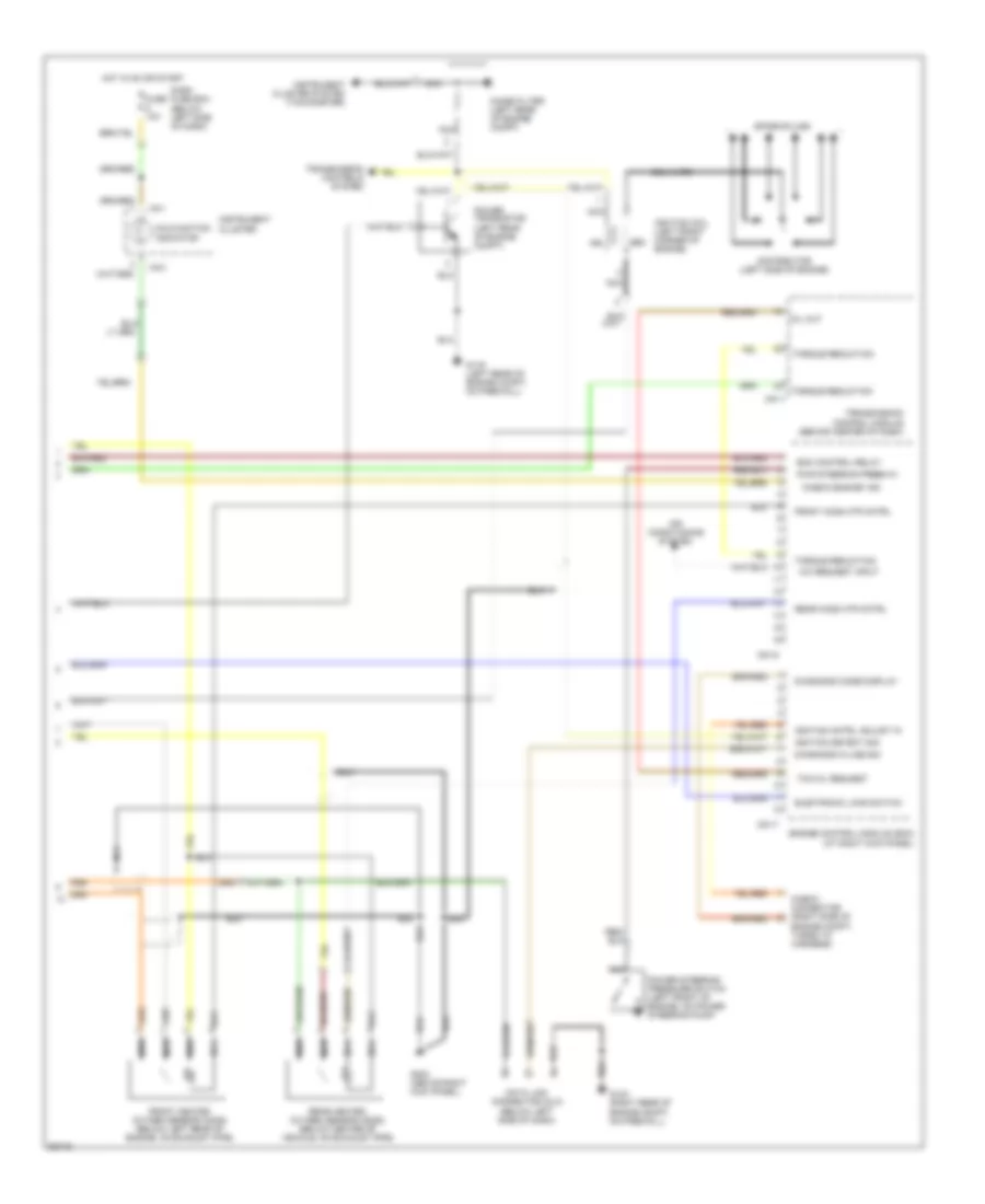
2.0L, Engine Performance Wiring Diagrams (1 of 3) for Hyundai Sonata GL 1997

List of elements for 2.0L, Engine Performance Wiring Diagrams (1 of 3) for Hyundai Sonata GL 1997:
- (a/t)
- (left rear of engine compt, on firewall)
- (m/t)
- (right side of engine compt)
- (right side of engine, near coolant outlet)
- (tp) sensor (on throttle body assembly)
- A/c control relay
- A/t
- Acc
- Air conditioning system
- Air flow sensor input
- Barometric press barometric press barometric press
- Barometric pressure sensor
- Battery
- Battery back-up
- Battery battery battery
- C01-4 c01-4 c01-4 c01-4 c01-4 c01-4
- C01-5 c01-5 c01-5 c01-5 c01-5 c01-5
- Cmp signal/ckp signal
- Coil control
- Coil control coil control coil control
- Coolant temp sensor
- Crankshaft pos sens
- Dash fuse box (below left side of dash)
- Egr cntrl solenoid
- Electronic load det
- Engine compartment fuse/relay box
- Engine control module (ecm) (at right kick panel)
- Engine coolant temperature (ect) sensor
- Frt ho2s sens
- Fuel injector #1
- Fuel injector #2 fuel injector #2 fuel injector #2
- Fuel injector #3
- Fuel injector #4 fuel injector #4 fuel injector #4
- Fuel pump control
- Fuse 10a
- G116
- G203 (at right kick panel)
- Ground
- Hot at all times
- Hot in on or start
- Idle switch
- Idle switch input
- Ignition input ignition input ignition input
- Ignition switch
- Intake air temp sens in
- Intake air temperature sensor
- Lock
- M/t
- Man diff pres sens
- Manifold differential pressure (mdp) sensor (ex. calif) (left side of firewall)
- Nca
- P/n (a/t),ground (m/t)
- Purge control sol
- Rear ho2s sens
- Red
- Sensor ground
- Sensor pwr 5v
- Solid state
- Start
- Start relay (in engine compt fuse/ relay box)
- Starting signal input
- Stepper control a
- Stepper control b
- Stepper control c stepper control c stepper control c
- Stepper control d stepper control d stepper control d
- Throttle pos sensor in throttle pos sensor in
- Throttle position
- Transmission controls system
- Transmission range switch (closed in park or neutral) (lower right front of engine, in top of transmission)
- Vehicle speed sensor
- Vehicle speed sensor (on transmission)
- Volume air flow (vaf) sensor assembly (right side of engine compt, in air cleaner assembly)
- Volume air flow sensor
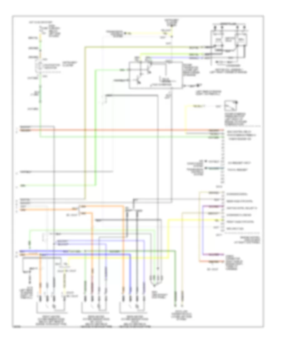
2.0L, Engine Performance Wiring Diagrams (2 of 3) for Hyundai Sonata GL 1997
List of elements for 2.0L, Engine Performance Wiring Diagrams (2 of 3) for Hyundai Sonata GL 1997:
- Brake pedal switch
- Calif
- Camshaft position (cmp) sensor (ex. calif) (on left front of engine)
- Cooling fans system
- Crankshaft position (ckp) sensor (calif) (on front of engine)
- Crankshaft position (ckp) sensor (ex. calif) (on front of engine)
- Defogger system
- Diode
- Ex. calif
- Exhaust gas exhaust gas exhaust gas recirculation recirculation recirculation control control control solenoid valve solenoid valve solenoid valve (ex. calif) (ex. calif) (ex. calif) (left side of (left side of (left side of firewall)
- Exterior lights system
- Fuel fuel fuel fuel fuel fuel injector 1 injector 1 injector 1 injector 1 injector 1 injector 1
- Fuel fuel fuel fuel fuel fuel injector 2 injector 2 injector 2 injector 2 injector 2 injector 2
- Fuel fuel fuel fuel fuel fuel injector 3 injector 3 injector 3 injector 3 injector 3 injector 3
- Fuel fuel fuel fuel fuel fuel injector 4 injector 4 injector 4 injector 4 injector 4 injector 4
- Fuel pump (in rear of of fuel tank)
- Fuel pump inspection connector (right side of engine compt, taped to harness)
- G116 (left rear of engine compt, on firewall)
- G304 (behind left side
- Idle speed control (isc) motor (on throttle body assembly)
- Nca
- Of rear seat)
- Purge control purge control purge control solenoid solenoid solenoid (left side of (left side of (left side of firewall) firewall) firewall)
- Sfi control relay (above right kick panel)
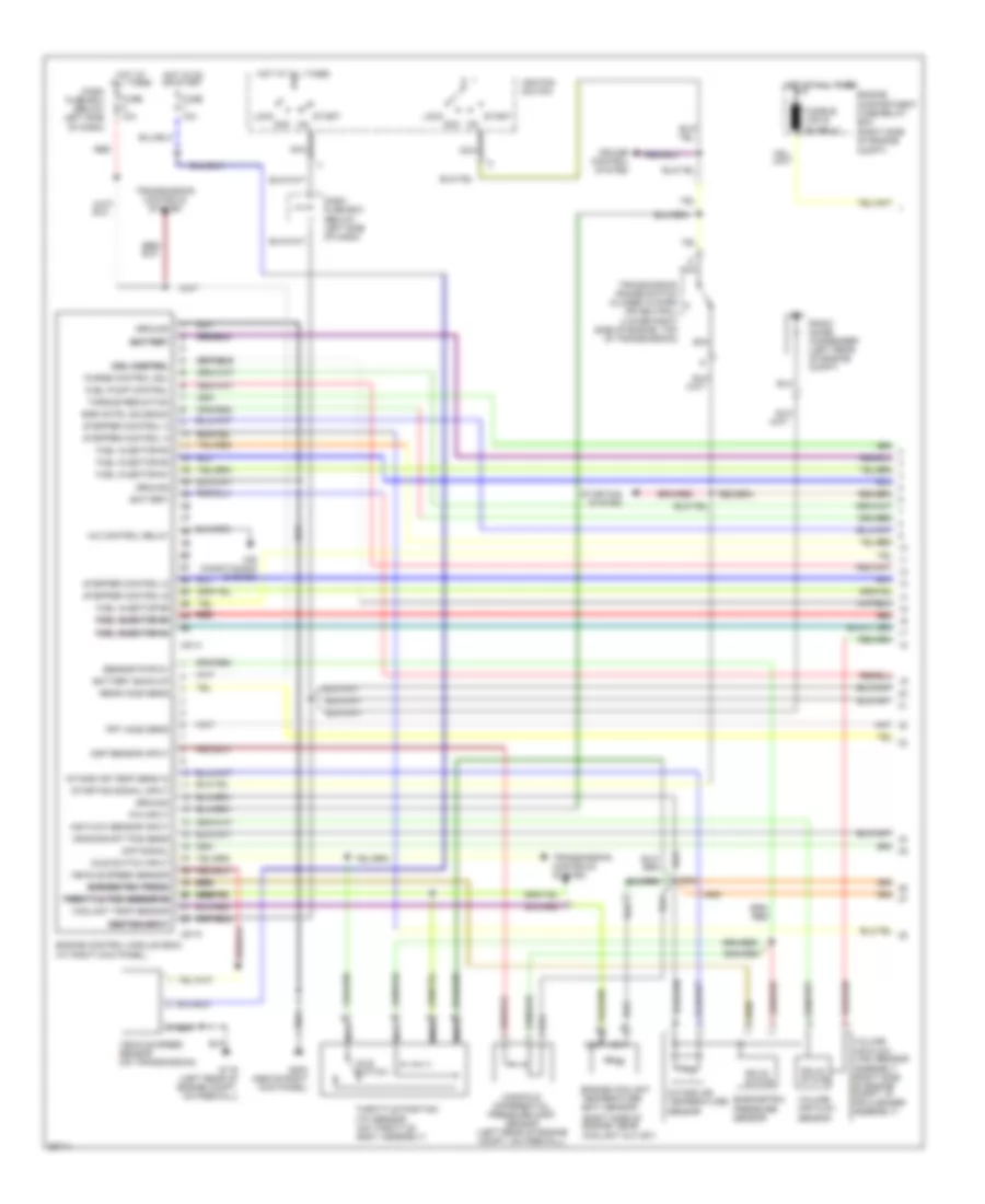
2.0L, Engine Performance Wiring Diagrams (3 of 3) for Hyundai Sonata GL 1997
List of elements for 2.0L, Engine Performance Wiring Diagrams (3 of 3) for Hyundai Sonata GL 1997:
- "check engine" ind
- (calif)
- (ex. calif)
- (left front corner of engine)
- (left rear of engine compt, on firewall)
- A/c request input
- Air conditioning system
- C01-6
- C01-7
- Calif
- Check connector (right side of engine compt, taped to harness)
- Condenser
- Dash fuse box (below left side of dash)
- Data link connector (dlc) (lower left side of dash)
- Diagnosis k-line sig
- Diagnosis signal
- Ecm control relay
- Engine control module (ecm) (at right kick panel)
- Ex. calif
- Front heated oxygen sensor (ho2s) (below left rear of engine, on exhaust pipe)
- Front ho2s htr cntrl
- Fuse 10a
- G116
- G116 (left rear of engine compt, on firewall)
- G203 (above right kick panel)
- Hot in on or start
- I16-3
- Ignition cntrl adjust in
- Ignition coil assembly
- Ignition coils
- Instrument cluster
- Instrument cluster system
- Malfunction indicator
- Nca
- Power steering pressure pump (left front of engine, on power steering pump)
- Power transistor (lower left rear corner of engine)
- Pwr steering press in
- Rear heated oxygen sensor (ho2s) (calif) (below center of vehicle, on exhaust pipe)
- Rear heated oxygen sensor (ho2s) (ex. calif) (below center of vehicle, on exhaust pipe)
- Rear ho2s htr cntrl
- Rpm input sig
- Solid state
- Spark plugs
- Tach interface
- Tcm mil request
- Transmission controls system
3.0L
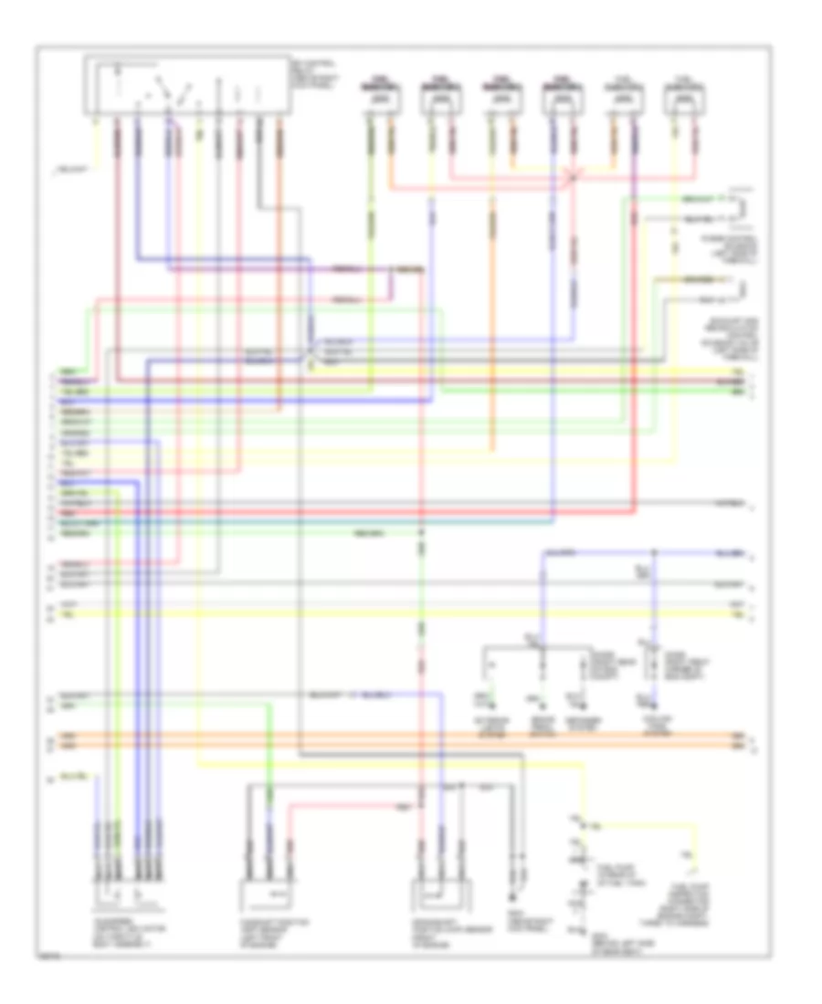
3.0L, Engine Performance Wiring Diagrams (1 of 3) for Hyundai Sonata GL 1997
List of elements for 3.0L, Engine Performance Wiring Diagrams (1 of 3) for Hyundai Sonata GL 1997:
- (right side of engine compt)
- (right side of engine, near coolant outlet)
- (tp) sensor (on throttle body assembly)
- A/c control relay
- Acc
- Air conditioning system
- Air flow sensor input
- Barometric press barometric press barometric press
- Barometric pressure sensor
- Battery
- Battery back-up
- Battery battery battery
- C51-4
- C51-5
- Cmp signal
- Coil control coil control coil control
- Coolant temp sensor
- Crankshaft pos sens
- Cruise control system
- Dash fuse box (below left side of dash)
- Egr cntrl solenoid
- Engine compartment fuse/relay box
- Engine control module (ecm) (at right kick panel)
- Engine coolant temperature (ect) sensor
- Frt ho2s sens
- Fuel injector #1
- Fuel injector #2
- Fuel injector #3
- Fuel injector #4 fuel injector #4 fuel injector #4
- Fuel injector #5 fuel injector #5 fuel injector #5
- Fuel injector #6
- Fuel pump control
- Fuse 10a
- G116 (left rear of engine compt, on firewall)
- G203 (above right kick panel)
- Ground
- Hot at all times
- Hot in on or start
- Idle switch
- Idle switch input
- Ignition input ignition input ignition input
- Ignition switch
- Intake air temp sens in
- Intake air temperature sensor
- Lock
- Manifold differential pressure (mdp) sensor (left rear of engine compt, on firewall)
- Mdp sensor input
- Nca
- P/n input
- Purge control sol
- Radio noise condenser (left rear of engine compt)
- Rear ho2s sens
- Red
- Red red red
- Sensor pwr 5v
- Solid state
- Start
- Starting signal input
- Starting system
- Stepper control a
- Stepper control b
- Stepper control c
- Stepper control d
- Throttle pos sensor in throttle pos sensor in throttle pos sensor in throttle pos sensor in throttle pos sensor in
- Throttle position
- Torque reduction
- Transmission controls system
- Transmission range switch (closed in park or neutral) (lower right side of engine, top of transmission)
- Vehicle speed sensor
- Vehicle speed sensor (on transmission)
- Volume air flow (vaf) sensor assembly (right side of engine compt, in air cleaner assembly)
- Volume air flow sensor
3.0L, Engine Performance Wiring Diagrams (2 of 3) for Hyundai Sonata GL 1997
List of elements for 3.0L, Engine Performance Wiring Diagrams (2 of 3) for Hyundai Sonata GL 1997:
- Brake pedal switch
- Camshaft position (cmp) sensor (left front of engine)
- Cooling fans system
- Crankshaft position (ckp) sensor (front of engine)
- Defogger system
- Diode (right front corner of eng compt)
- Diode (right rear of eng compt)
- Exhaust gas recirculation control solenoid valve (left side of firewall)
- Exterior lights system
- Fuel fuel fuel fuel injector 1 injector 1 injector 1 injector 1
- Fuel fuel fuel fuel injector 2 injector 2 injector 2 injector 2
- Fuel fuel fuel fuel injector 3 injector 3 injector 3 injector 3
- Fuel fuel fuel fuel injector 4 injector 4 injector 4 injector 4
- Fuel injector 5
- Fuel injector 6
- Fuel pump (in rear of of fuel tank)
- Fuel pump inspection connector (right side of engine compt, taped to harness)
- G203 (above right kick panel)
- G304 (behind left side
- Idle speed control (isc) motor (on throttle body assembly)
- Nca
- Nca nca nca
- Of rear seat)
- Purge control solenoid (left side of firewall)
- Red
- Red red red
- Sfi control relay (above right kick panel)
3.0L, Engine Performance Wiring Diagrams (3 of 3) for Hyundai Sonata GL 1997
List of elements for 3.0L, Engine Performance Wiring Diagrams (3 of 3) for Hyundai Sonata GL 1997:
- "check engine" ind
- (at right kick panel)
- A/c request input
- Air conditioning system
- C51-6
- C51-7
- C81-1
- Check connector (right side of engine compt, taped to harness)
- Coil wire
- Dash fuse box (below left side of dash)
- Data link connector (dlc) (below left side of dash)
- Diagnosis code display
- Diagnosis k-line sig
- Distributor (left side of engine)
- Ecm control relay
- Electronic load switch
- Engine control module (ecm)
- Front heated oxygen sensor (ho2s) (below left rear of engine, on exhaust pipe)
- Front ho2s htr cntrl
- Fuse 10a
- G116 (left rear of engine compt, on firewall)
- G123 (right rear of engine compt, on firewall)
- G203 (above right kick panel)
- Hot in on or start
- I16-1
- I16-3
- Ignition cntrl adjust in
- Ignition coil (left front corner of engine)
- Ignition detect sig
- Instrument cluster
- Instrument cluster system (tachometer)
- Malfunction indicator
- Mil out
- Nca
- Noise filter (left rear of engine compt)
- Power steering pressure switch (left front of engine, on power steering pump)
- Power transistor (left rear of engine compt)
- Pri
- Pwr steering press in
- Rear heated oxygen sensor (ho2s) (below center of vehicle, on exhaust pipe)
- Rear ho2s htr cntrl
- Sec
- Spark plugs
- Tcm mil request
- Torque reduction
- Transmission control module (behind center of dash)
- Transmission controls system