ENGINE PERFORMANCE
1.6L
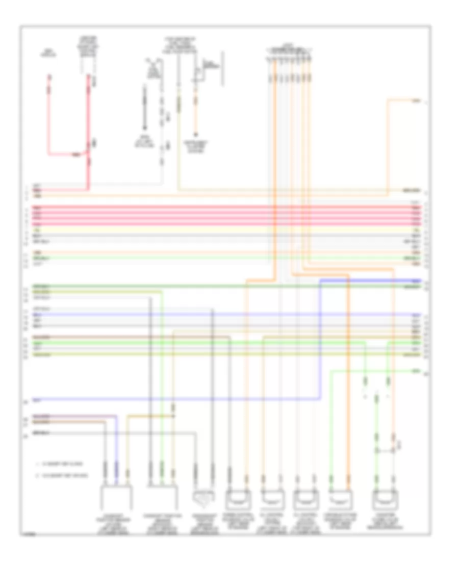
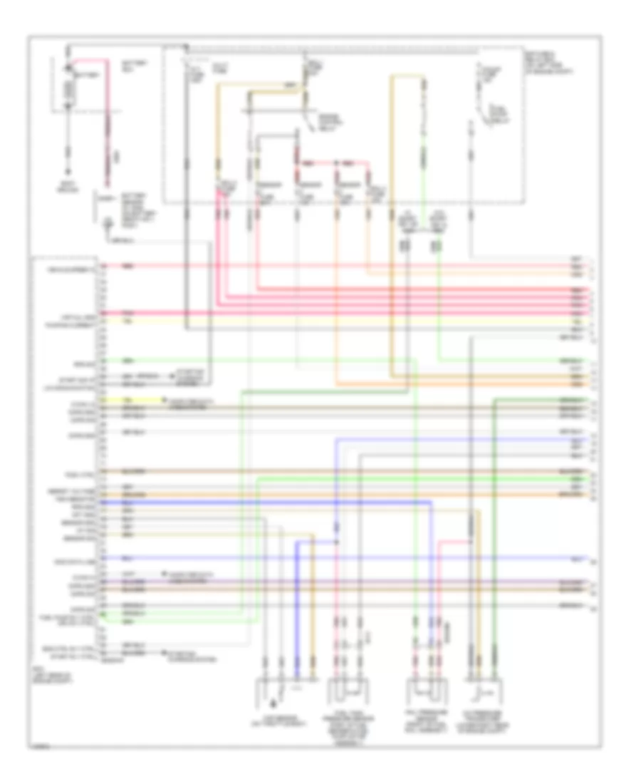
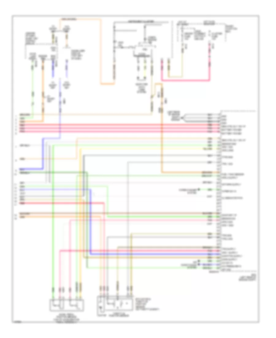
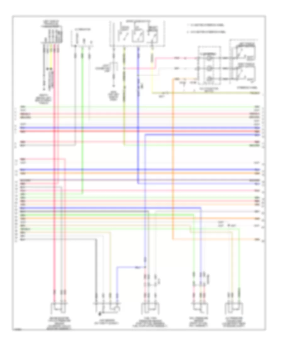
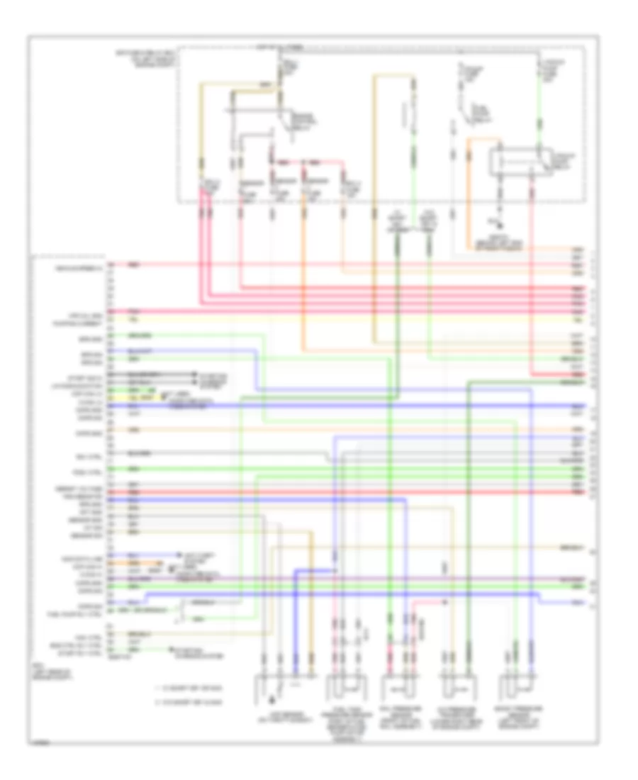
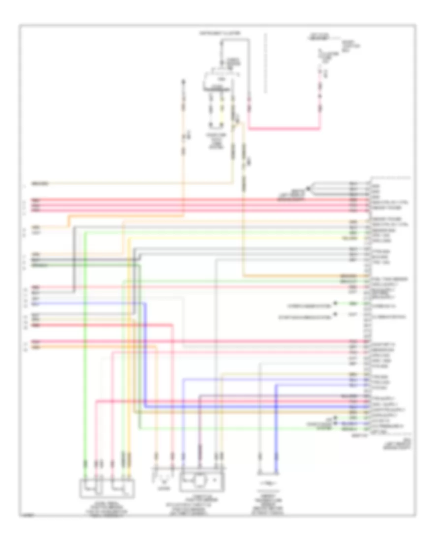
1.6L, Engine Performance Wiring Diagram, with DCT (1 of 5) for Hyundai Veloster Turbo R-Spec 2014

List of elements for 1.6L, Engine Performance Wiring Diagram, with DCT (1 of 5) for Hyundai Veloster Turbo R-Spec 2014:
- A/c pressure transducer (lower right rear of engine compt)
- Alt fuse 125a
- Ams fuse 10a
- Apt gnd
- Battery
- Battery box
- Body ground
- C-can hi
- C-can lo
- Ccp can hi
- Ccp can lo
- Ckps gnd
- Ckps sig
- Cmps gnd
- Cmps sig
- Computer data lines system
- E/r fuse & relay box (on left side of engine compt)
- Ecm (left rear of engine compt)
- Ecu 1 fuse 30a
- Ecu 2 fuse 15a
- Ecu 4 fuse 15a
- Ef11
- Eggd-mk
- Eggdinj
- Eng ctrl rly ctrl
- Engine control relay
- F/pump fuse 15a
- Fuel pump relay
- Fuel pump rly ctrl (or ccv ctrl)
- Fuel tank pressure sensor (part of fuel sender & fuel pump motor assembly)
- Iat sig
- Immo data line
- Lin communication
- Lin line
- Map sensor (on throttle body)
- Multi fuse
- Nernst voltage
- Pcsv ctrl
- Pnk
- Pumping current
- Rail pressure sensor (front of fuel rail assembly)
- Red
- Rps gnd
- Rps sig
- Sensor 1 fuse 20a
- Sensor 2 fuse 10a
- Sensor 3 fuse 15a
- Sensor gnd
- Sensor sig
- Snsr +
- Start rly ctrl
- Start sig in
- Starting/ charging system
- Trim resistor
- Vehicle speed in
- Virtual gnd
- W/ smart key & immo
- W/o smart key or immo
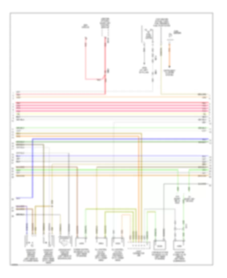
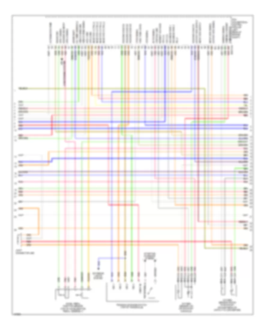
1.6L, Engine Performance Wiring Diagram, with DCT (2 of 5) for Hyundai Veloster Turbo R-Spec 2014
List of elements for 1.6L, Engine Performance Wiring Diagram, with DCT (2 of 5) for Hyundai Veloster Turbo R-Spec 2014:
- (center of dash) smart key control module
- (left front of cylinder head)
- (top center of fuel tank) fuel sender & fuel pump motor
- (top front of cylinder head)
- Camshaft position sensor (exhaust) (right rear of cylinder head)
- Camshaft position sensor (intake) (left rear of cylinder head)
- Canister close valve (above left rear suspension)
- Crankshaft position sensor (left rear of engine block)
- Ef11
- Em11
- Em61
- Esc module
- Fuel
- Fuel pump motor
- Gf06 (at left "b" pillar)
- Instrument cluster system
- Joint connector je01
- M13-b
- Mf11
- Oil control valve 1 (intake)
- Oil control valve 2 (exhaust)
- Pnk
- Purge control solenoid valve (left rear of engine)
- Red
- Sender
- Variable intake solenoid valve (left rear of engine)
- W/ smart key & immo
- W/o smart key or immo
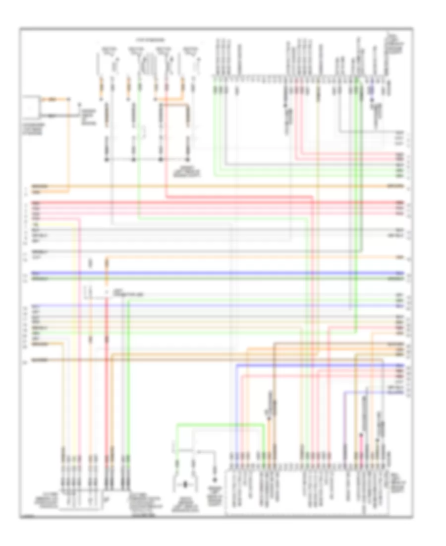
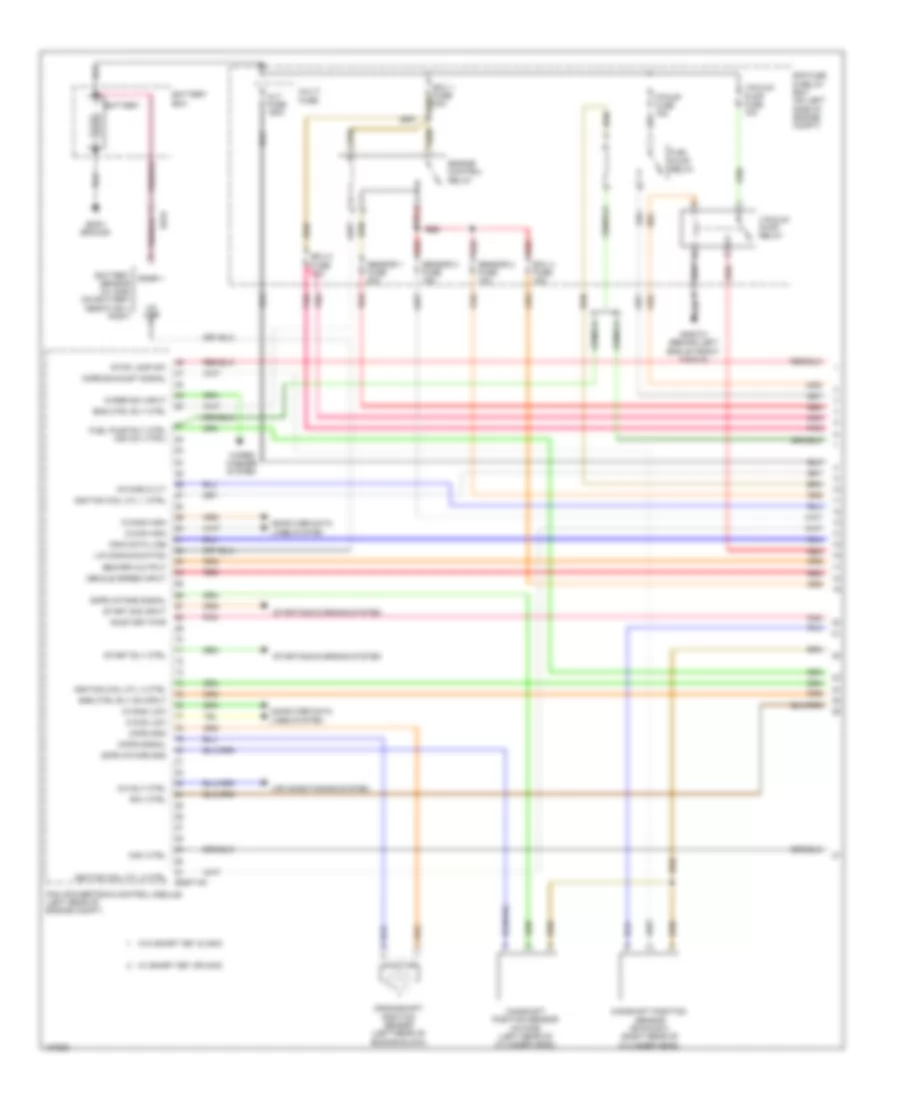
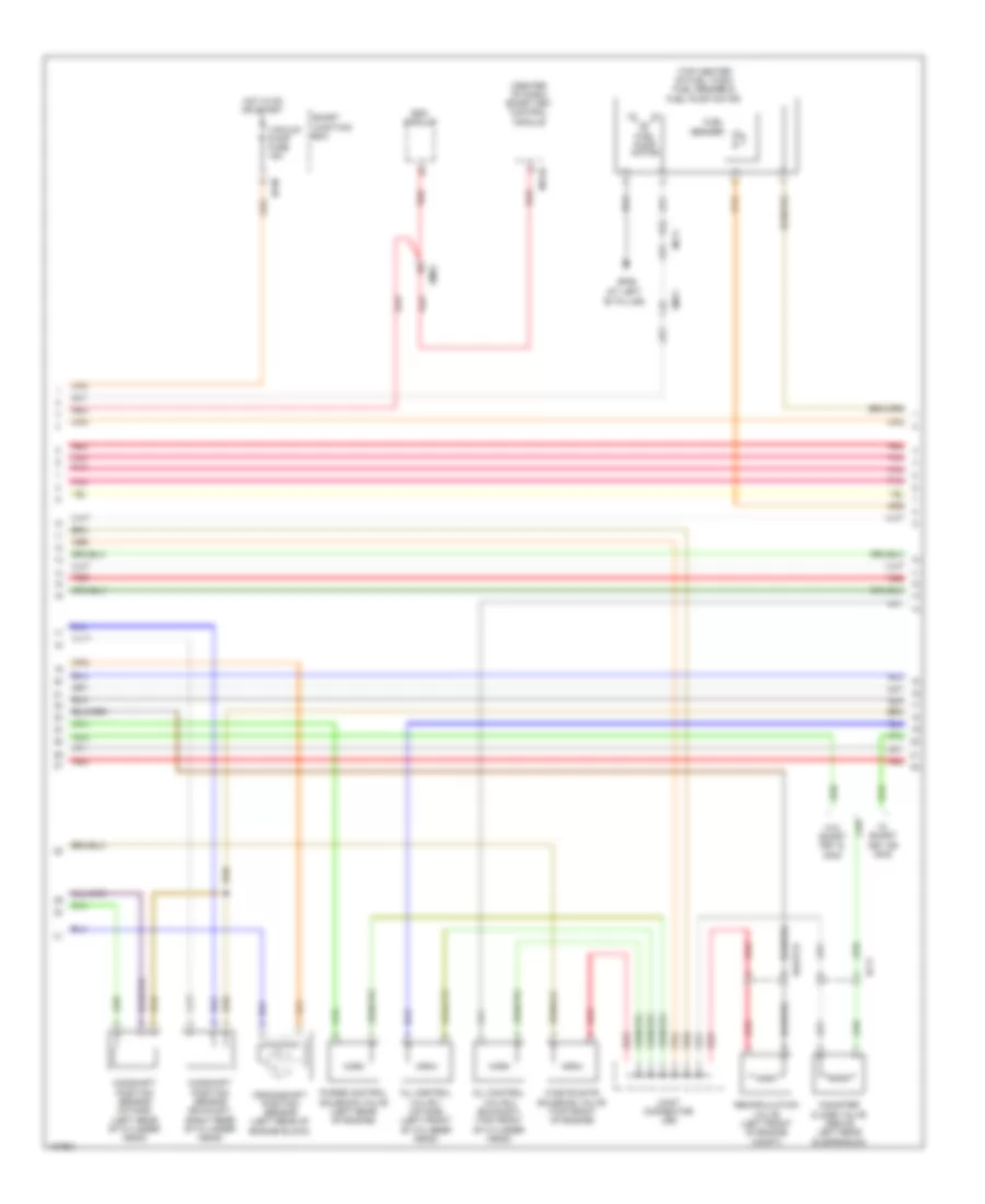
1.6L, Engine Performance Wiring Diagram, with DCT (3 of 5) for Hyundai Veloster Turbo R-Spec 2014
List of elements for 1.6L, Engine Performance Wiring Diagram, with DCT (3 of 5) for Hyundai Veloster Turbo R-Spec 2014:
- (rear of engine) gggd09
- (top of engine)
- A/con rly ctrl
- Air
- Alternator com
- Blower sw in
- Brake light sw
- Brake test sw
- C/fan rly ctrl hi
- C/fan rly ctrl lo
- Condenser (top rear of engine)
- Conditioning system
- Cooling fans system
- Cvvt exhaust
- Cvvt intake
- Defogger system
- Ecm (left rear of engine compt)
- Ects gnd
- Ects sig
- Eggd-ma
- Elec load defroster
- Engine rpm output
- Etc output (+)
- Etc output (-)
- Fpcv (+)
- Fpcv (-)
- Ftps sig
- Fuel pump rly ctrl (or ccvt ctrl)
- Gggd06 (left rear of engine compt)
- Gggd07 (left rear of engine compt)
- Ign coil ctrl cyl 1
- Ign coil ctrl cyl 2
- Ign coil ctrl cyl 3
- Ign coil ctrl cyl 4
- Ignition coil 1
- Ignition coil 2
- Ignition coil 3
- Ignition coil 4
- Injector 1 ctrl (+)
- Injector 1 ctrl (-)
- Injector 2 ctrl (+)
- Injector 2 ctrl (-)
- Injector 3 ctrl (+)
- Injector 3 ctrl (-)
- Injector 4 ctrl (+)
- Injector 4 ctrl (-)
- Knock sensor (left side of engine block)
- Knock sensor gnd
- Knock sensor sig
- Nca
- Oxygen sensor (down) (in exhaust, downstream of catalytic converter)
- Oxygen sensor (up) (on exhaust manifold)
- Pnk
- Red
- Sensor heater
- System conditioning air
- System cooling fans
- Vis ctrl
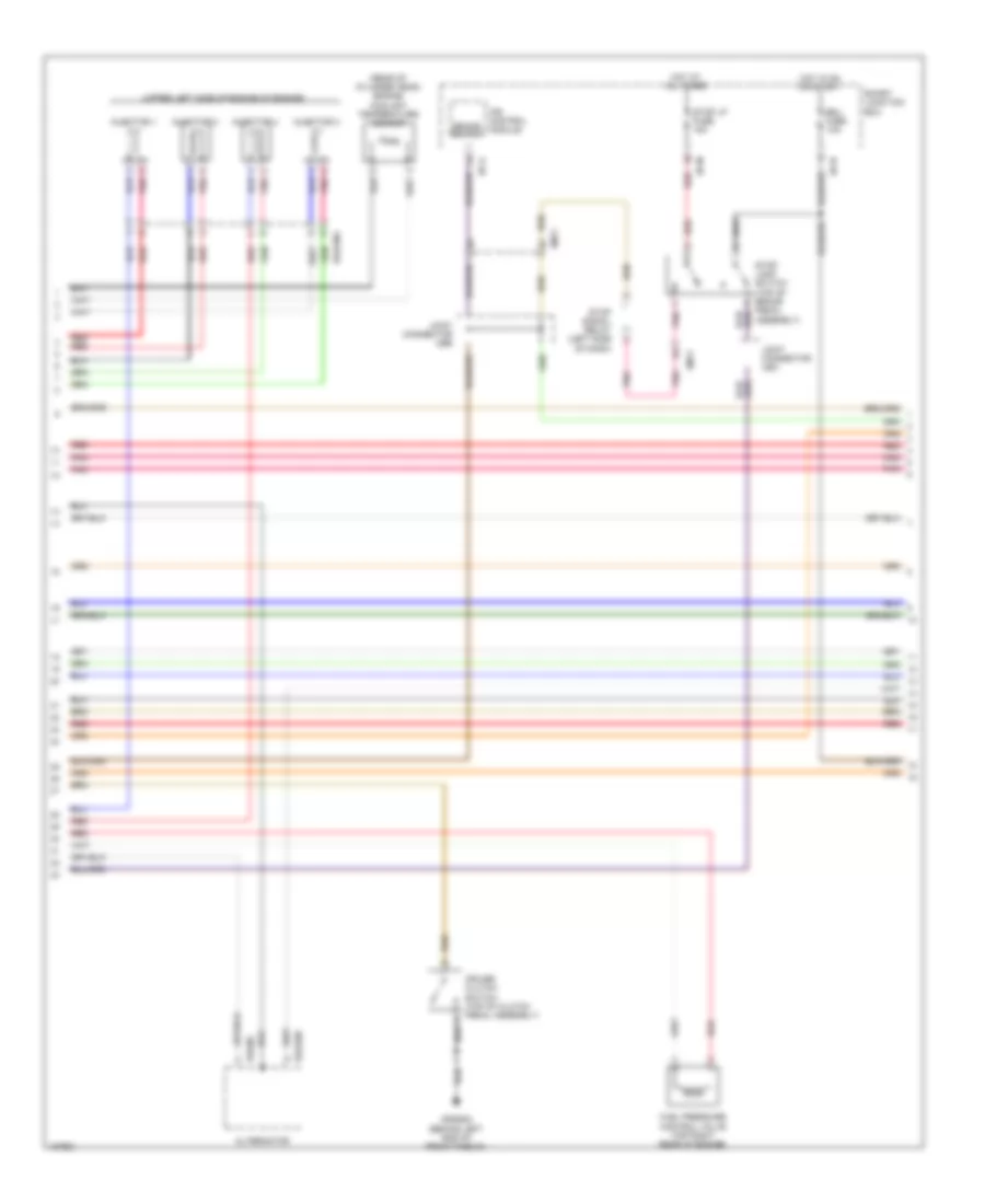
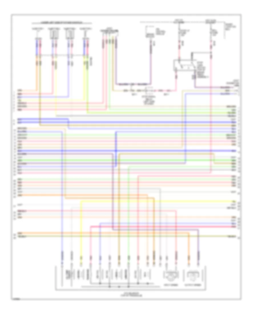
1.6L, Engine Performance Wiring Diagram, with DCT (4 of 5) for Hyundai Veloster Turbo R-Spec 2014
List of elements for 1.6L, Engine Performance Wiring Diagram, with DCT (4 of 5) for Hyundai Veloster Turbo R-Spec 2014:
- (rear of cylinder head) engine coolant temperature sensor
- (under left side of intake manifold)
- Alternator
- Brake switch
- Ecu 1 fuse 10a
- Eggginj
- Em11
- Exterior lights system
- Fuel pressure control valve (top right rear of engine)
- Hot at all times
- Hot in on or start
- I/p-a
- I/p-m
- I/p-n
- Injector 1
- Injector 2
- Injector 3
- Injector 4
- Ips control module
- Pnk
- Red
- Smart junction box
- Stop lamp switch (top of brake pedal assembly)
- Stop lp fuse 15a
- Stop signal relay (left side of dash)
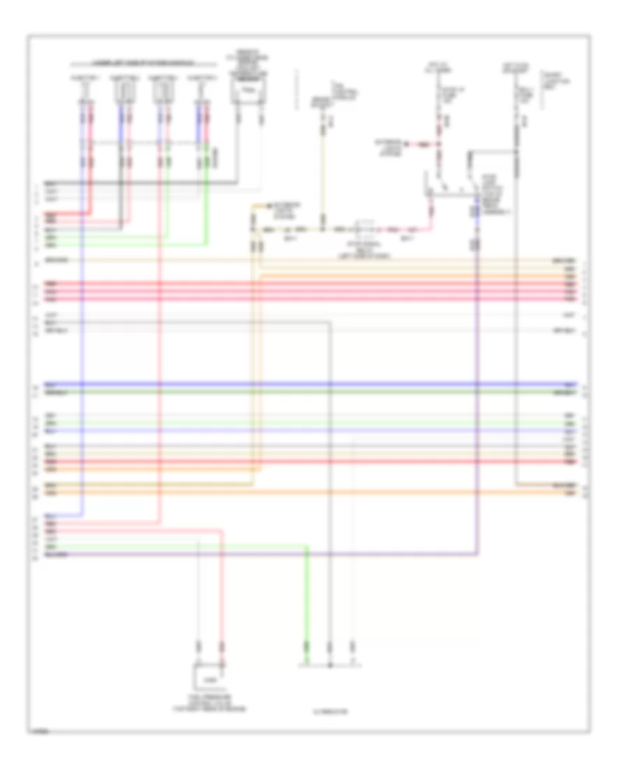
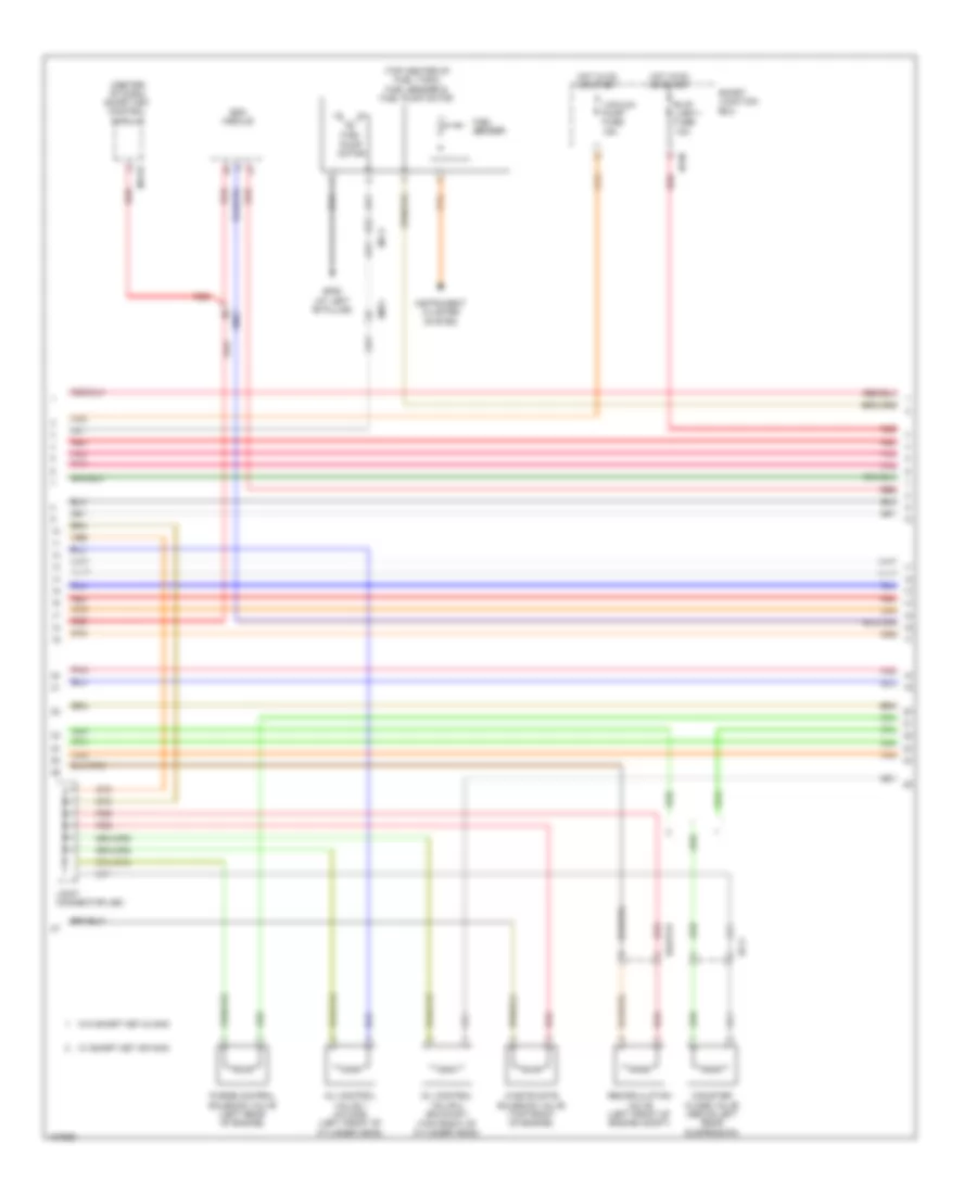
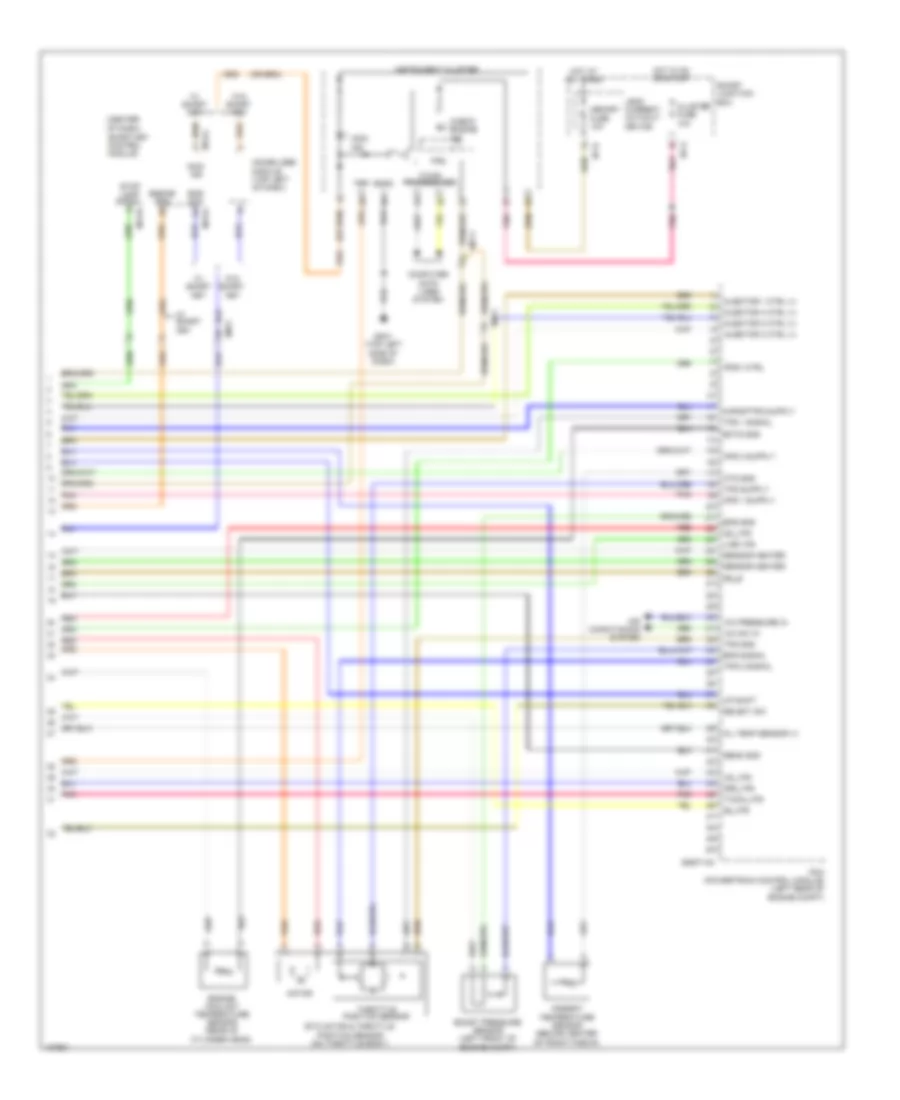
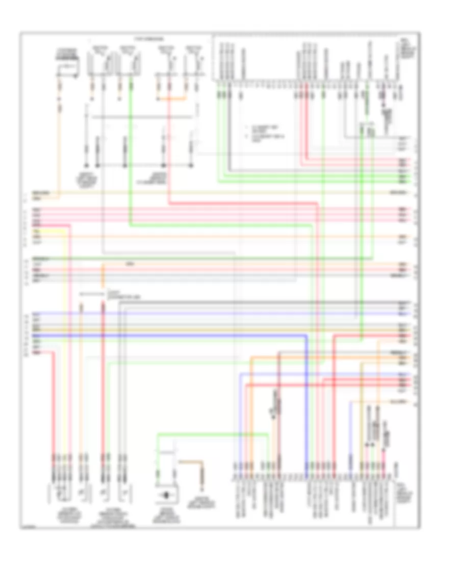
1.6L, Engine Performance Wiring Diagram, with DCT (5 of 5) for Hyundai Veloster Turbo R-Spec 2014
List of elements for 1.6L, Engine Performance Wiring Diagram, with DCT (5 of 5) for Hyundai Veloster Turbo R-Spec 2014:
- (center of dash) smart key control module
- (left rear of engine compt) gggd06
- A/c pressure in
- A/c sw in
- Accel pedal position sensor (top of accelerator pedal assembly)
- Air conditioning system
- Alternator pwm
- Aps 1 gnd
- Aps 1 sig
- Aps 2 gnd
- Aps 2 sig
- Apt sig
- C-can transceiver
- Check engine ind
- Cluster fuse 10a
- Computer data lines system
- Ecm (left rear of engine compt)
- Eggd-mk
- Em11
- Ems com
- Eng ctrl rly ctrl
- Engine rpm
- Etc motor & throttle position sensor (on throttle body)
- Ftps gnd
- Fuel tank sensor
- Gnd
- Hot at all times
- Hot in on or start
- I/p-g
- I/p-h
- Immo ind
- Immobilizer module (top left of dash)
- Instrument cluster
- Leak current autocut device
- M13-a
- M13-b
- M13-c
- Mcu
- Memory fuse 10a
- Memory power
- Mf11
- Motor
- On/start i/p
- Pnk
- Red
- Sensor gnd
- Sensor sig
- Smart junction box
- Stop lamp signal
- Throttle position sensor
- Tps gnd
- Tps1 sig
- Tps2 sig
- W/ smart key
- W/o smart key
- Wiper sw in
- Wiper/washer system
1.6L, Engine Performance Wiring Diagram, without DCT (1 of 5) for Hyundai Veloster Turbo R-Spec 2014
List of elements for 1.6L, Engine Performance Wiring Diagram, without DCT (1 of 5) for Hyundai Veloster Turbo R-Spec 2014:
- A/c pressure transducer (lower right rear of engine compt)
- Alt fuse 125a
- Apt gnd
- Battery
- Battery box
- Body ground
- C-can hi
- C-can lo
- Ckps gnd
- Ckps sig
- Cmps gnd
- Cmps sig
- Computer data lines system
- E/r fuse & relay box (on left side of engine compt)
- Ecm (left rear of engine compt)
- Ecu 1 fuse 30a
- Ecu 2 fuse 15a
- Ecu 4 fuse 15a
- Ee01
- Ef11
- Eggg-mk
- Eggginj
- Eng ctrl rly ctrl
- Engine control relay
- Fuel pump relay
- Fuel pump rly ctrl (or ccv ctrl)
- Fuel tank pressure sensor (part of fuel sender & fuel pump motor assembly)
- Iat sig
- Immo data line
- Lin communication
- Lin line
- Map sensor (on throttle body)
- Multi fuse
- Nernst voltage
- Pcsv ctrl
- Pnk
- Pumping current
- Rail pressure sensor (front of fuel rail assembly)
- Red
- Rps gnd
- Rps sig
- Sensor fuse 10a
- Sensor fuse 15a
- Sensor fuse 20a
- Sensor gnd
- Sensor sig
- Snsr +
- Start rly ctrl
- Start sig i/p
- Starting/ charging system
- Trim resistor
- Vehicle speed in
- Virtual gnd
- W/ smart key or immo
- W/o smart key & immo
1.6L, Engine Performance Wiring Diagram, without DCT (2 of 5) for Hyundai Veloster Turbo R-Spec 2014
List of elements for 1.6L, Engine Performance Wiring Diagram, without DCT (2 of 5) for Hyundai Veloster Turbo R-Spec 2014:
- (at left "b" pillar)
- (center of dash) smart key control module
- (top center of fuel tank) fuel sender & fuel pump motor
- Camshaft position sensor (exhaust) (right rear of cylinder head)
- Camshaft position sensor (intake) (left rear of cylinder head)
- Canister close valve (above left rear suspension)
- Crankshaft position sensor (left rear of engine block)
- Ef11
- Em11
- Em61
- Esc module
- Fuel
- Fuel pump motor
- Gf06
- Instrument cluster system
- Joint connector uec
- M13-b
- Mf11
- Oil control valve 1 (intake) (left front of cylinder head)
- Oil control valve 2 (exhaust) (top front of cylinder head)
- Pnk
- Purge control solenoid valve (left rear of engine)
- Red
- Sender
- Variable intake solenoid valve (left rear of engine)
- W/ smart key or immo
- W/o smart key & immo
1.6L, Engine Performance Wiring Diagram, without DCT (3 of 5) for Hyundai Veloster Turbo R-Spec 2014
List of elements for 1.6L, Engine Performance Wiring Diagram, without DCT (3 of 5) for Hyundai Veloster Turbo R-Spec 2014:
- (or ccv ctrl) fuel pump rly ctrl
- (top of engine)
- A/con rly ctrl
- Air
- Alternator com
- Blower sw in
- Brake light sw
- Brake test sw
- C/fan rly ctrl hi
- C/fan rly ctrl lo
- Clutch switch
- Condenser (top rear of engine)
- Conditioning system
- Cooling fans system
- Cvvt exhaust
- Cvvt intake
- Defogger system
- Ecm (left rear of engine compt)
- Ects gnd
- Ects sig
- Eggg-ma
- Elec load defroster
- Engine rpm output
- Etc output (+)
- Etc output (-)
- Fpcv (+)
- Fpcv (-)
- Ftps sig
- Gggg06 (left rear of engine compt)
- Gggg07 (left rear of engine compt)
- Gggg09 (rear of engine)
- Ign coil ctrl cyl 1
- Ign coil ctrl cyl 2
- Ign coil ctrl cyl 3
- Ign coil ctrl cyl 4
- Ignition coil 1
- Ignition coil 2
- Ignition coil 3
- Ignition coil 4
- Injector 1 ctrl (+)
- Injector 1 ctrl (-)
- Injector 2 ctrl (+)
- Injector 2 ctrl (-)
- Injector 3 ctrl (+)
- Injector 3 ctrl (-)
- Injector 4 ctrl (+)
- Injector 4 ctrl (-)
- Joint connector ued
- Knock sensor (left side of engine block)
- Knock sensor gnd
- Knock sensor sig
- Nca
- Oxygen sensor (down) (in exhaust, downstream of catalytic converter)
- Oxygen sensor (up) (on exhaust manifold)
- Pnk
- Red
- Sensor heater
- System conditioning air
- System cooling fans
- Vis ctrl
1.6L, Engine Performance Wiring Diagram, without DCT (4 of 5) for Hyundai Veloster Turbo R-Spec 2014
List of elements for 1.6L, Engine Performance Wiring Diagram, without DCT (4 of 5) for Hyundai Veloster Turbo R-Spec 2014:
- (rear of cylinder head) engine coolant temperature sensor
- (upper left side of engine of engine)
- Alternator
- Brake switch
- Cruise clutch switch (top of clutch pedal assembly)
- Ecu fuse 10a
- Egg06
- Eggg06
- Eggginj
- Em11
- Fuel pressure control valve (top right rear of engine)
- Gggg02 (behind left end of front fascia)
- Hot at all times
- Hot in on or start
- I/p-a
- I/p-m
- I/p-n
- Injector 1
- Injector 2
- Injector 3
- Injector 4
- Ips control module
- Joint connector uea
- Joint connector ueb
- Pnk
- Red
- Smart junction box
- Stop lamp switch (top of brake pedal assembly)
- Stop lp fuse 15a
- Stop signal relay (left side of dash)
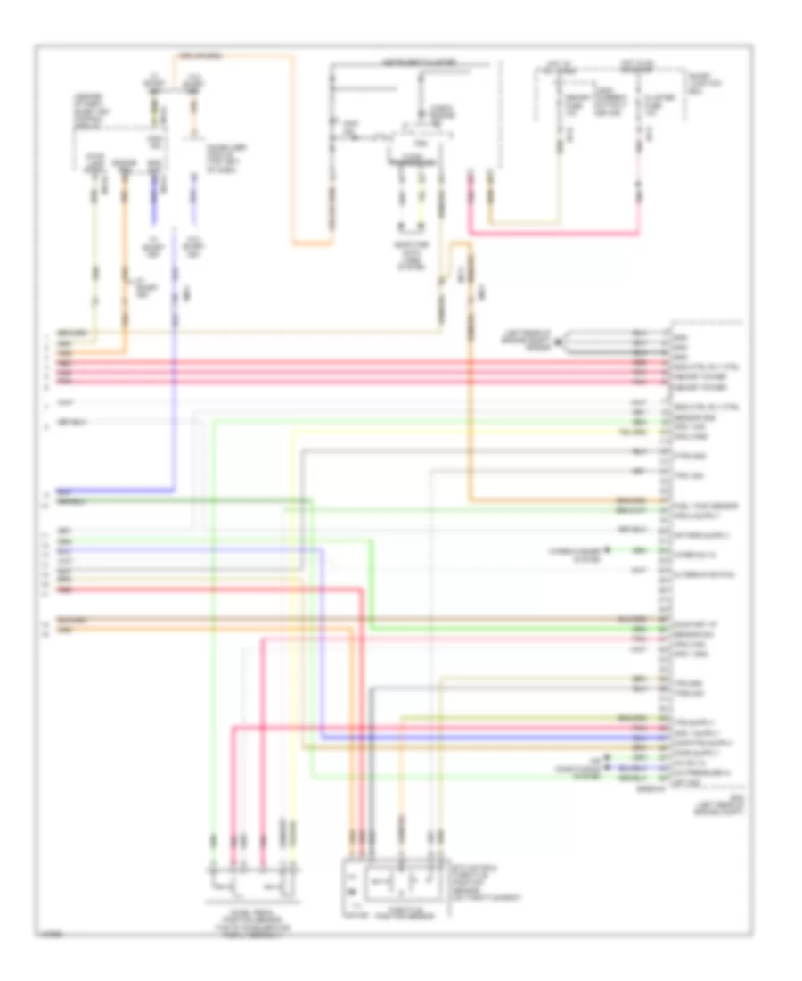
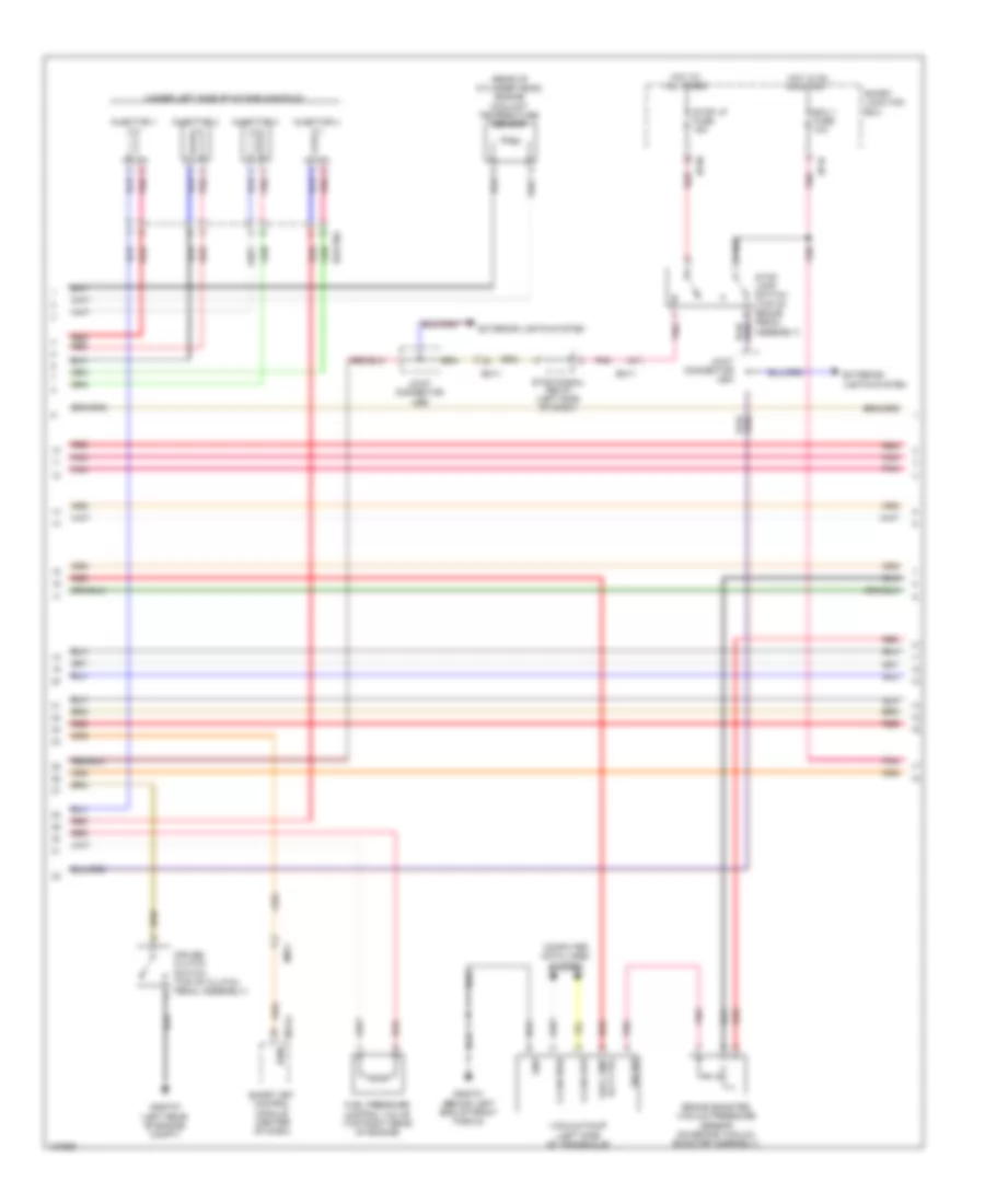
1.6L, Engine Performance Wiring Diagram, without DCT (5 of 5) for Hyundai Veloster Turbo R-Spec 2014
List of elements for 1.6L, Engine Performance Wiring Diagram, without DCT (5 of 5) for Hyundai Veloster Turbo R-Spec 2014:
- (center of dash) smart key control module
- (left rear of engine compt) gggg06
- A/c pressure in
- A/c sw in
- Accel pedal position sensor (top of accelerator pedal assembly)
- Air conditioning system
- Alternator pwm
- Aps 1 gnd
- Aps 1 sig
- Aps 2 gnd
- Aps 2 sig
- Apt sig
- Battery power
- C-can transceiver
- Check engine ind
- Cluster fuse 10a
- Computer data lines system
- Ecm (left rear of engine compt)
- Eggg-mk
- Em11
- Ems com
- Eng ctrl rly 'on' i/p
- Engine rpm
- Etc motor & throttle position sensor (on throttle body)
- Ftps gnd
- Fuel tank sensor
- Gnd
- Hot at all times
- Hot in on or start
- I/p-g
- I/p-h
- Immo ind
- Immobilizer module (top left of dash)
- Instrument cluster
- Leak current autocut device
- M13-a
- M13-b
- M13-c
- Mcu
- Memory fuse 10a
- Mf11
- Motor
- On/start i/p
- Pnk
- Red
- Sensor gnd
- Sensor sig
- Smart junction box
- Stop lamp signal
- Throttle position sensor
- Tps 1 sig
- Tps 2 sig
- Tps gnd
- W/ smart key
- W/o smart key
- Wiper sw in
- Wiper/washer system
1.6L TURBO
1.6L Turbo, Engine Performance Wiring Diagram, A/T (1 of 7) for Hyundai Veloster Turbo R-Spec 2014
List of elements for 1.6L Turbo, Engine Performance Wiring Diagram, A/T (1 of 7) for Hyundai Veloster Turbo R-Spec 2014:
- A/c rly ctrl
- Air conditioning system
- Alt fuse 150a
- Battery
- Battery box
- Body ground
- C-can high
- C-can low
- C-can2 high
- C-can2 low
- Camshaft position sensor (exhaust) (right rear of cylinder head)
- Camshaft position sensor (intake) (left rear of cylinder head)
- Ckps gnd
- Ckps signal
- Cmps exhaust signal
- Cmps intake gnd
- Cmps intake signal
- Computer data lines system
- Crankshaft position sensor (left rear of engine block)
- E/r fuse & relay box (on left side of engine compt)
- Ecu 1 fuse 30a
- Ecu 2 fuse 15a
- Ecu 4 fuse 15a
- Ee31
- Eggt-ak
- Eng ctrl rly ctrl
- Eng ctrl rly on input
- Eng rpm output
- Engine control relay
- Fuel pump relay
- Fuel pump rly ctrl (or ccv ctrl)
- Gggt01 (behind left end of front fascia)
- Ignition coil cyl 1 ctrl
- Ignition coil cyl 3 ctrl
- Ignition coil cyl 4 ctrl
- Immo data line
- Intake cvvt
- Lin communication
- Lin line
- Multi fuse
- On/start pwr
- Pcm (powertrain control module) (left rear of engine compt)
- Pnk
- Rcv ctrl
- Red
- Sensor 1 fuse 20a
- Sensor 2 fuse 10a
- Sensor 3 fuse 15a
- Snsr +
- Start rly ctrl
- Start sig input
- Starting/charging system
- Stop lamp sw
- Vacuum pump fuse 15a
- Vacuum pump relay
- Vehicle speed input
- W/ smart key or immo
- W/o smart key & immo
- Wgv ctrl
- Wiper sw input
- Wiper/ washer system
1.6L Turbo, Engine Performance Wiring Diagram, A/T (2 of 7) for Hyundai Veloster Turbo R-Spec 2014
List of elements for 1.6L Turbo, Engine Performance Wiring Diagram, A/T (2 of 7) for Hyundai Veloster Turbo R-Spec 2014:
- (center of dash) smart key control module
- (top center of fuel tank) fuel sender & fuel pump motor
- (top front of cylinder head)
- B-up lamp 1 fuse 15a
- Canister close valve (above left rear suspension)
- Ef11
- Eggtcr
- Em11
- Em61
- Esc module
- Fuel pump motor
- Fuel sender
- Gf06 (at left "b" pillar)
- Hot in on or start
- I/p-m
- Instrument cluster system
- Joint connector uec
- M13-b
- Mf11
- Oil control valve 1 (intake) (left front of cylinder head)
- Oil control valve 2 (exhaust)
- Pnk
- Purge control solenoid valve (left rear of engine)
- Recirculation valve (left front of engine compt)
- Red
- Smart junction box
- Vacuum pump fuse 15a
- W/ smart key or immo
- W/o smart key & immo
- Waste gate solenoid valve (top front of engine)
1.6L Turbo, Engine Performance Wiring Diagram, A/T (3 of 7) for Hyundai Veloster Turbo R-Spec 2014
List of elements for 1.6L Turbo, Engine Performance Wiring Diagram, A/T (3 of 7) for Hyundai Veloster Turbo R-Spec 2014:
- (left side of engine block) knock sensor
- (or ccv ctrl) fuel pump rly ctrl
- (top of engine)
- (top rear of engine) condenser
- (top right rear of engine) fuel pressure control valve
- Alternator com
- Apt gnd
- Apt signal
- Apt/rps/bps sply
- Cmps exhaust gnd
- Cooling fans pwm ctrl
- Cooling fans system
- Defogger system
- Eggt-ak
- Elec load defroster
- Eng ctrl rly on i/p
- Etc output (+)
- Etc output (-)
- Exhaust cvvt
- Ftps gnd
- Gggt06 (left rear of engine compt)
- Gggt07 (left rear of engine compt)
- Gggt09 (rear of cylinder head)
- Gnd
- Iat signal
- Ignition coil 1
- Ignition coil 2
- Ignition coil 3
- Ignition coil 4
- Ignition coil cyl 2 ctrl
- Mem pwr
- Pcm (powertrain control module) (left rear of engine compt)
- Pnk
- Red
- Rps gnd
- Rps signal
- Sensor gnd
- Sensor signal
- Vacuum sensor gnd
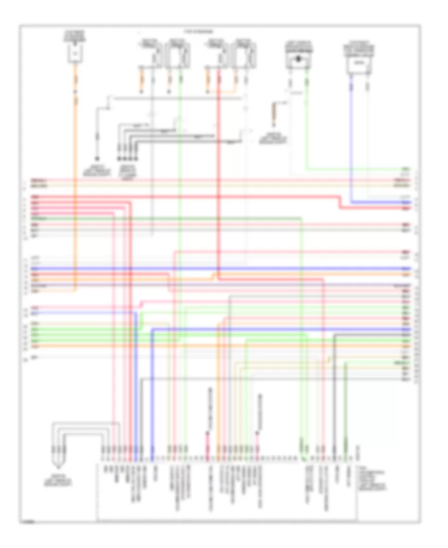
1.6L Turbo, Engine Performance Wiring Diagram, A/T (4 of 7) for Hyundai Veloster Turbo R-Spec 2014
List of elements for 1.6L Turbo, Engine Performance Wiring Diagram, A/T (4 of 7) for Hyundai Veloster Turbo R-Spec 2014:
- (left side of transaxle) vacuum pump
- A/c pressure transducer (lower right rear of engine compt)
- Alternator
- Battery
- Brake booster vacuum pressure sensor (on brake vacuum booster assembly)
- C-can high
- C-can low
- Clockspring
- Com
- Computer data lines system
- Down shift
- Ef11
- Eggtinj
- Em11
- Fuel tank pressure sensor (part of fuel sender & fuel pump motor assembly)
- Gggt01 (behind left end of front fascia)
- Gm02 (top left side of dash)
- Gnd
- Joint connector umb
- Left paddle shift switch
- M01-h
- M01-r
- Map sensor (on throttle body)
- Multi-function switch
- Nca
- Pnk
- Rail pressure sensor (front of fuel rail assembly)
- Red
- Right paddle shift switch
- Select switch
- Shift down
- Shift up
- Signal sw vacc pmp rly ctrl
- Sport mode switch
- Steering wheel
- Up shift
- W/ heated steering wheel
- W/o heated steering wheel
1.6L Turbo, Engine Performance Wiring Diagram, A/T (5 of 7) for Hyundai Veloster Turbo R-Spec 2014
List of elements for 1.6L Turbo, Engine Performance Wiring Diagram, A/T (5 of 7) for Hyundai Veloster Turbo R-Spec 2014:
- Accel pedal position sensor (top of accelerator pedal assembly)
- Alternator pwm
- Aps 1 gnd
- Aps 1 signal
- Aps 2 gnd
- Aps 2 signal
- Ats signal
- Blower sw input
- Brake sw
- Conditioning system air
- Down shift
- Ects signal
- Eggt-aa
- Exterior lights system
- Fpcv (+)
- Fpcv (-)
- Ftps signal
- Fuel tank level
- Injector 1 ctrl (-)
- Injector 2 ctrl (-)
- Injector 3 ctrl (-)
- Injector 4 ctrl (-)
- Input spd signal
- Joint connector ued
- Knock sens gnd
- Knock sens signal
- Nca
- Nernst voltage
- Oil temp sensor (-)
- On/st in
- Output spd signal
- Oxygen sensor (down) (in exhaust, downstream of catalytic converter)
- Oxygen sensor (up) (on exhaust manifold)
- P/n switch
- Pcm (powertrain control module) (left rear of engine compt)
- Pnk
- Posi sw code s1
- Posi sw code s2
- Posi sw code s3
- Posi sw code s4
- Pumping current
- Red
- Sensor signal
- Sig 1
- Sig 2
- Sig 3
- Sig 4
- Solenoid pwr 1
- Solenoid pwr 2
- Ss_a
- Starting/ charging system
- Transaxle range switch (top of transaxle)
- Trim resistor
- Vertual gnd
1.6L Turbo, Engine Performance Wiring Diagram, A/T (6 of 7) for Hyundai Veloster Turbo R-Spec 2014
List of elements for 1.6L Turbo, Engine Performance Wiring Diagram, A/T (6 of 7) for Hyundai Veloster Turbo R-Spec 2014:
- (under left side of intake manifold)
- 26 vfs
- 35r vfs
- Atm solenoid (top of transaxle)
- Brake switch
- Ecu fuse 10a
- Eggtinj
- Em11
- Hot at all times
- Hot in on or start
- I/p-a
- I/p-m
- I/p-n
- Injector 1
- Injector 2
- Injector 3
- Injector 4
- Input speed
- Ips control module
- Joint connector uea
- Joint connector ueb
- Line vfs
- Od vfs
- Output speed
- Pnk
- Red
- Sensor oil temp
- Smart junction box
- Ss-a
- Ss-b
- Stop lamp switch (top of brake pedal assembly)
- Stop lp fuse 15a
- Stop signal relay (left side of dash)
- T/con vfs
- Ud vfs
1.6L Turbo, Engine Performance Wiring Diagram, A/T (7 of 7) for Hyundai Veloster Turbo R-Spec 2014
List of elements for 1.6L Turbo, Engine Performance Wiring Diagram, A/T (7 of 7) for Hyundai Veloster Turbo R-Spec 2014:
- (center of dash)
- 26_vfs
- 35r_vfs
- A/c pressure in
- A/c sw in
- Air conditioning system
- Ambient temperature sensor (behind center of front fascia)
- Ats gnd
- Boost pressure sensor (left front of engine compt)
- Bps gnd
- Bps signal
- C-can transceiver
- Check engine ind
- Cluster fuse 10a
- Computer data lines system
- Cylinder head)
- Ects gnd
- Eggt-aa
- Em11
- Ems com
- Engine coolant temperature sensor (rear of
- Engine rpm
- Etc motor & throttle position sensor (on throttle body)
- Gm01 (top left side of dash)
- Hot at all times
- Hot in on or start
- I/p-g
- I/p-h
- Immo ind
- Immobilizer module (top left of dash)
- Injector 1 ctrl (+)
- Injector 2 ctrl (+)
- Injector 3 ctrl (+)
- Injector 4 ctrl (+)
- Instrument cluster
- Leak current autocut device
- Line vfs
- M13-a
- M13-b
- M13-c
- Mcu
- Memory fuse 10a
- Mf11
- Motor
- Od_vfs
- Oil temp sensor (+)
- Pcm (powertrain control module) (left rear of engine compt)
- Pcsv ctrl
- Pnk
- Red
- Select sw
- Sens gnd
- Sensor heater
- Sgnd
- Smart junction box
- Smart key control module
- Ss_b
- Stop lamp signal
- T/con_vfs
- Throttle position sensor
- Tps 1 signal
- Tps 2 signal
- Tps gnd
- Trip (-)
- Ud_vfs
- Up shift
- W/ smart key
- W/o smart key
1.6L Turbo, Engine Performance Wiring Diagram, M/T (1 of 5) for Hyundai Veloster Turbo R-Spec 2014
List of elements for 1.6L Turbo, Engine Performance Wiring Diagram, M/T (1 of 5) for Hyundai Veloster Turbo R-Spec 2014:
- (not used)
- A/c pressure transducer (lower right rear of engine compt)
- Anti-theft system
- Apt gnd
- Boost pressure sensor (left front of engine compt)
- Bps gnd
- Bps sig
- C-can hi
- C-can lo
- Ccp can hi
- Ccp can lo
- Ckps gnd
- Ckps sig
- Cmps gnd
- Cmps sig
- Computer data lines system
- E/r fuse & relay box (on left side of engine compt)
- Ecm (left rear of engine compt)
- Ecu 1 fuse 30a
- Ecu 2 fuse 15a
- Ecu 4 fuse 15a
- Ef11
- Eggt-mk
- Eggtinj
- Em61
- Eng ctrl rly ctrl
- Engine control relay
- Fuel pump relay
- Fuel pump rly ctrl
- Fuel tank pressure sensor (part of fuel sender & fuel pump motor assembly)
- Gggt01 (behind left end of front fascia)
- Hot at all times
- Iat sig
- Immo data line
- Lin communication
- Map sensor (on throttle body)
- Nernst voltage
- Pcsv ctrl
- Pnk
- Pumping current
- Rail pressure sensor (front of fuel rail assembly)
- Rcv ctrl
- Red
- Rps gnd
- Rps sig
- Sensor fuse 10a
- Sensor fuse 15a
- Sensor fuse 20a
- Sensor gnd
- Sensor sig
- Start rly ctrl
- Start sig in
- Starting/ charging system
- Trim resistor
- Vaccum pump fuse 20a
- Vacuum pump relay
- Vehicle speed in
- Virtual gnd
- W/ smart key or immo
- W/o smart key & immo
- Wgv ctrl
1.6L Turbo, Engine Performance Wiring Diagram, M/T (2 of 5) for Hyundai Veloster Turbo R-Spec 2014
List of elements for 1.6L Turbo, Engine Performance Wiring Diagram, M/T (2 of 5) for Hyundai Veloster Turbo R-Spec 2014:
- (at left "b" pillar)
- (center of dash) smart key control module
- (top center of fuel tank) fuel sender & fuel pump motor
- Camshaft position sensor (exhaust) (right rear of cylinder head)
- Camshaft position sensor (intake) (left rear of cylinder head)
- Canister close valve (above left rear suspension)
- Crankshaft position sensor (left rear of engine block)
- Ef11
- Eggtcr
- Em11
- Em61
- Esc module
- Fuel pump motor
- Fuel sender
- Gf06
- Hot in on or start
- I/p-m
- Joint connector uec
- M13-b
- Mf11
- Oil control valve 1 (intake) (left front of cylinder head)
- Oil control valve 2 (exhaust) (top front of cylinder head)
- Pnk
- Purge control solenoid valve (left rear of engine)
- Recirculation valve (left front of engine compt)
- Red
- Smart junction box
- Vacuum pump fuse 15a
- W/ smart key or immo
- W/o smart key & immo
- Waste gate solenoid valve (top front of engine)
1.6L Turbo, Engine Performance Wiring Diagram, M/T (3 of 5) for Hyundai Veloster Turbo R-Spec 2014
List of elements for 1.6L Turbo, Engine Performance Wiring Diagram, M/T (3 of 5) for Hyundai Veloster Turbo R-Spec 2014:
- (top of engine)
- (top rear of engine) condenser
- A/c rly ctrl
- Air
- Alternator com
- Blower sw in
- Brake light sw
- Brake test sw
- C/fan rly ctrl lo
- Clutch switch
- Conditioning system
- Cooling fans system
- Cvvt exhaust
- Cvvt intake
- Defogger system
- Ecm (left rear of engine compt)
- Ects gnd
- Ects sig
- Eggt-ma
- Elec load defroster
- Engine rpm output
- Etc output (+)
- Etc output (-)
- Fpcv (+)
- Fpcv (-)
- Ftps sig
- Fuel pump rly ctrl
- Gggt06 (left rear of engine compt)
- Gggt07 (left rear of engine compt)
- Gggt09 (rear of cylinder head)
- Ign coil ctrl cyl 1
- Ign coil ctrl cyl 2
- Ign coil ctrl cyl 3
- Ign coil ctrl cyl 4
- Ignition coil 1
- Ignition coil 2
- Ignition coil 3
- Ignition coil 4
- Injector 1 ctrl (+)
- Injector 1 ctrl (-)
- Injector 2 ctrl (+)
- Injector 2 ctrl (-)
- Injector 3 ctrl (+)
- Injector 3 ctrl (-)
- Injector 4 ctrl (+)
- Injector 4 ctrl (-)
- Joint connector ued
- Knock sensor (left side of engine block)
- Knock sensor gnd
- Knock sensor sig
- Nca
- Oxygen sensor (down) (in exhaust, downstream of catalytic converter)
- Oxygen sensor (up) (on exhaust manifold)
- Pnk
- Red
- Sensor heater
- Starting/ charging system
- System conditioning air
- W/ smart key or immo
- W/o smart key & immo
1.6L Turbo, Engine Performance Wiring Diagram, M/T (4 of 5) for Hyundai Veloster Turbo R-Spec 2014
List of elements for 1.6L Turbo, Engine Performance Wiring Diagram, M/T (4 of 5) for Hyundai Veloster Turbo R-Spec 2014:
- (rear of cylinder head) engine coolant temperature sensor
- (under left side of intake manifold)
- Brake booster vacuum pressure sensor (on brake vacuum booster assembly)
- C-can high
- C-can low
- Computer data lines system
- Cruise clutch switch (top of clutch pedal assembly)
- Ecu 1 fuse 10a
- Eggtinj
- Em11
- Exterior lights system
- Fuel pressure control valve (top right rear of engine)
- Gggt01 (behind left end of front fascia)
- Gggt07 (left rear of engine compt)
- Gnd
- Hot at all times
- Hot in on or start
- I/p-m
- I/p-n
- Injector 1
- Injector 2
- Injector 3
- Injector 4
- Joint connector uea
- Joint connector ueb
- M13-a
- Pnk
- Red
- Rpm
- Sig sw
- Smart junction box
- Smart key control module (center of dash)
- Stop lamp switch (top of brake pedal assembly)
- Stop lp fuse 15a
- Stop signal relay (left side of dash)
- Vacc pmp rly ctrl
- Vacuum pump (left side of transaxle)
1.6L Turbo, Engine Performance Wiring Diagram, M/T (5 of 5) for Hyundai Veloster Turbo R-Spec 2014
List of elements for 1.6L Turbo, Engine Performance Wiring Diagram, M/T (5 of 5) for Hyundai Veloster Turbo R-Spec 2014:
- A/c pressure in
- A/c sw in
- Accel pedal position sensor (top of accelerator pedal assembly)
- Air conditioning system
- Alternator pwm
- Ambient temperature sensor (behind center of front fascia)
- Aps 1 gnd
- Aps 1 sig
- Aps 2 gnd
- Aps 2 sig
- Apt sig
- Ats gnd
- Ats sig
- Bvs gnd
- C-can transceiver
- Check engine ind
- Cluster fuse 10a
- Computer data lines system
- Ecm (left rear of engine compt)
- Eggt-mk
- Em11
- Eng ctrl rly ctrl
- Etc motor & throttle position sensor (on throttle body)
- Ftps gnd
- Fuel tank sensor
- Gggt06 (left rear of engine compt)
- Gnd
- Hot in on or start
- I/p-g
- Instrument cluster
- Mcu
- Memory power
- Mf11
- Motor
- On/start in
- Pnk
- Red
- Sensor gnd
- Sensor sig
- Smart junction box
- Starting/charging system
- Throttle position sensor
- Tps 1 sig
- Tps 2 sig
- Tps gnd
- Wiper sw in
- Wiper/washer system