ENGINE PERFORMANCE
3.5L
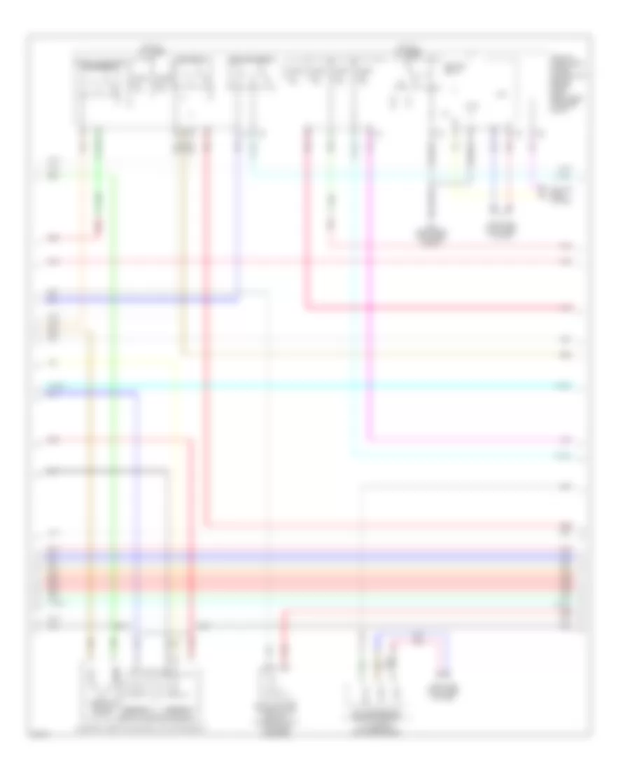
3.5L, Engine Performance Wiring Diagram (1 of 4) for Infiniti EX35 Journey 2009

List of elements for 3.5L, Engine Performance Wiring Diagram (1 of 4) for Infiniti EX35 Journey 2009:
- (front of right cylinder bank)
- (right front of engine) f34
- (top of left cylinder bank) ignition coil 2 (w/ power transistor)
- (top of left cylinder bank) ignition coil 4 (w/ power transistor)
- (top of left cylinder bank) ignition coil 6 (w/ power transistor)
- (top of right cylinder bank) condenser
- (top of right cylinder bank) ignition coil 1 (w/ power transistor)
- (top of right cylinder bank) ignition coil 3 (w/ power transistor)
- (top of right cylinder bank) ignition coil 5 (w/ power transistor)
- Af+1
- Af-1
- Afh1
- Afh2
- Avcc phase 1
- Avcc phase 2
- Avcc pos
- Avcc tps
- Close
- Crankshaft position sensor (pos)
- Cvtc 1
- Cvtc 2
- E phase 1
- E phase 2
- Ecm (engine control module) (right end of dash)
- Electric throttle control actuator (bank 2)
- Evap
- Evtc 1
- Evtc 2
- Exhaust valve timing control magnet retarder (bank 1) (front of right cylinder bank)
- Exhaust valve timing control magnet retarder (bank 2) (front of left cylinder bank)
- F101
- F102
- Fpr
- Gnd
- Gnd a(tps)
- Gnd pos
- Gnda intpres
- Ign 1
- Ign 2
- Ign 3
- Ign 4
- Ign 5
- Ign 6
- Ignsw
- Intake valve timing control solenoid valve (bank 1)
- Intake valve timing control solenoid valve (bank 2) (front of left cylinder bank)
- M95 (right side of dash)
- Motor1 1
- Motor1 2
- Motor2 1
- Motor2 2
- Motrly1
- Nca
- O2hr1
- O2hr2
- Open
- Phase 1
- Phase 2
- Plug spark
- Pnk
- Pos
- Red
- Sensor 1
- Sensor 2
- Spark plug
- Ssoff
- Throttle control motor
- Throttle position sensor
- Tps1 1
- Tps1 2
- Tps2 1
- Tps2 2
- Vmot1
- Vmot2
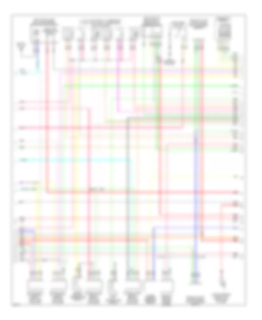
3.5L, Engine Performance Wiring Diagram (2 of 4) for Infiniti EX35 Journey 2009
List of elements for 3.5L, Engine Performance Wiring Diagram (2 of 4) for Infiniti EX35 Journey 2009:
- A/t assembly (on transmission)
- Can h
- Can l
- Close
- Computer data lines system
- Cooling fans system
- Cpu
- E22 (right rear of engine compt)
- Ecm relay
- Electric throttle control actuator (bank 1)
- Evap canister purge volume control solenoid valve (top rear of engine)
- Fuel pump relay
- Fuse 10a
- Fuse 15a
- Hot at all times
- Ignition relay
- Ipdm e/r (intelligent power distribution module engine room) (right rear of engine compt)
- Nca
- Open
- Pnk
- Red
- Sensor 1
- Sensor 2
- St rly
- Tcm (transmission control module)
- Throttle control motor
- Throttle control motor relay
- Throttle position sensor
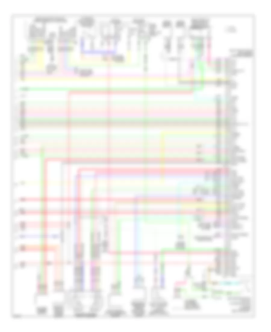
3.5L, Engine Performance Wiring Diagram (3 of 4) for Infiniti EX35 Journey 2009
List of elements for 3.5L, Engine Performance Wiring Diagram (3 of 4) for Infiniti EX35 Journey 2009:
- (1, 3 & 5: top of right cylinder bank) (2, 4 & 6: top of left cylinder bank) fuel injectors
- (left "c" pillar) b24
- (left front of engine compt) mass air flow sensor (bank 2)
- (top of fuel tank) fuel level sensor unit & fuel pump (main)
- Air fuel ratio (a/f) sensor 1 (bank 1) (right side of engine)
- Air fuel ratio (a/f) sensor 1 (bank 2) (left side of engine)
- Camshaft position sensor (phase) (bank 2)
- Combination meter
- Comm amp lcd
- Comm amp mtr
- Comm lcd amp
- Comm mtr amp
- Engine coolant temperature sensor
- Engine oil temperature sensor
- Exhaust valve timing control position sensor (bank 1)
- Exhaust valve timing control position sensor (bank 2)
- Fuel pump
- Fuel tank temperature sensor
- Heated oxygen sensor 2 (bank 1) (left side of engine)
- Heated oxygen sensor 2 (bank 2) (left side of engine)
- M95 (right side of dash)
- Nca
- Pnk
- Power steering control unit (right side of dash)
- Power steering pressure sensor
- Red
- Snow mode switch
- Tacho eng
3.5L, Engine Performance Wiring Diagram (4 of 4) for Infiniti EX35 Journey 2009
List of elements for 3.5L, Engine Performance Wiring Diagram (4 of 4) for Infiniti EX35 Journey 2009:
- (behind center console) unified meter & a/c amplifier
- (on brake pedal bracket) stop lamp switch
- (or pnk)
- (or red)
- (right end of dash) ecm (engine control module)
- (right front of engine compt) mass air flow sensor (bank 1)
- Accelerator pedal position sensor
- Af+2
- Af-2
- Amp lcd
- Amp meter
- Aps1
- Aps2
- Ascd brake switch (w/o icc) icc brake switch (w/ icc) (on brake pedal bracket)
- Ascdsw
- At snow sw
- Avcc aps1
- Avcc aps2
- Avcc ftprs
- Avcc pdpress
- Bat pwr
- Batt
- Battery current sensor
- Bnc sw
- Brake
- Camshaft position sensor (phase) (bank 1)
- Can h
- Can l
- Cdcv
- Computer data lines system
- Cruise control system
- Cursen
- E103
- Evap canister vent control valve (under right rear of vehicle)
- Evap control system pressure sensor
- F102
- Ftprs
- Fuse 10a
- Fuse block (j/b) (left kick panel)
- Gnd
- Gnd a
- Gnd a(aps1)
- Gnd a(aps2)
- Gnd phase 2
- Gnd pspres
- Gnda ascd
- Gnda cursen
- Gnda o2 tw to
- Gnda pdpress
- Gnda qa ta
- Hot at all times
- Hot in on or start
- Icc brake hold relay (left side of engine compt)
- Ign pwr
- Inj 1
- Inj 2
- Inj 3
- Inj 4
- Inj 5
- Inj 6
- Kline
- Knk1
- Knk2
- Knock sensor (bank 1)
- Knock sensor (bank 2)
- Lcd amp
- M107
- M11 (left end of dash)
- M66
- M67
- M95 (right side of dash)
- Meter amp
- Nca
- Neut h
- O2sr1
- O2sr2
- Pdpress
- Pnk
- Pspres
- Qa1+
- Qa2+
- Red
- Refrigerant pressure sensor (right front of engine compt)
- Sens gnd
- Sensor 1
- Sensor 2
- Ta+2
- Ta1
- Tacho
- To1
- Vbr
- Vehcan h1
- Vehcan l1
- W/ icc
- W/o icc