ENGINE PERFORMANCE
5.0L
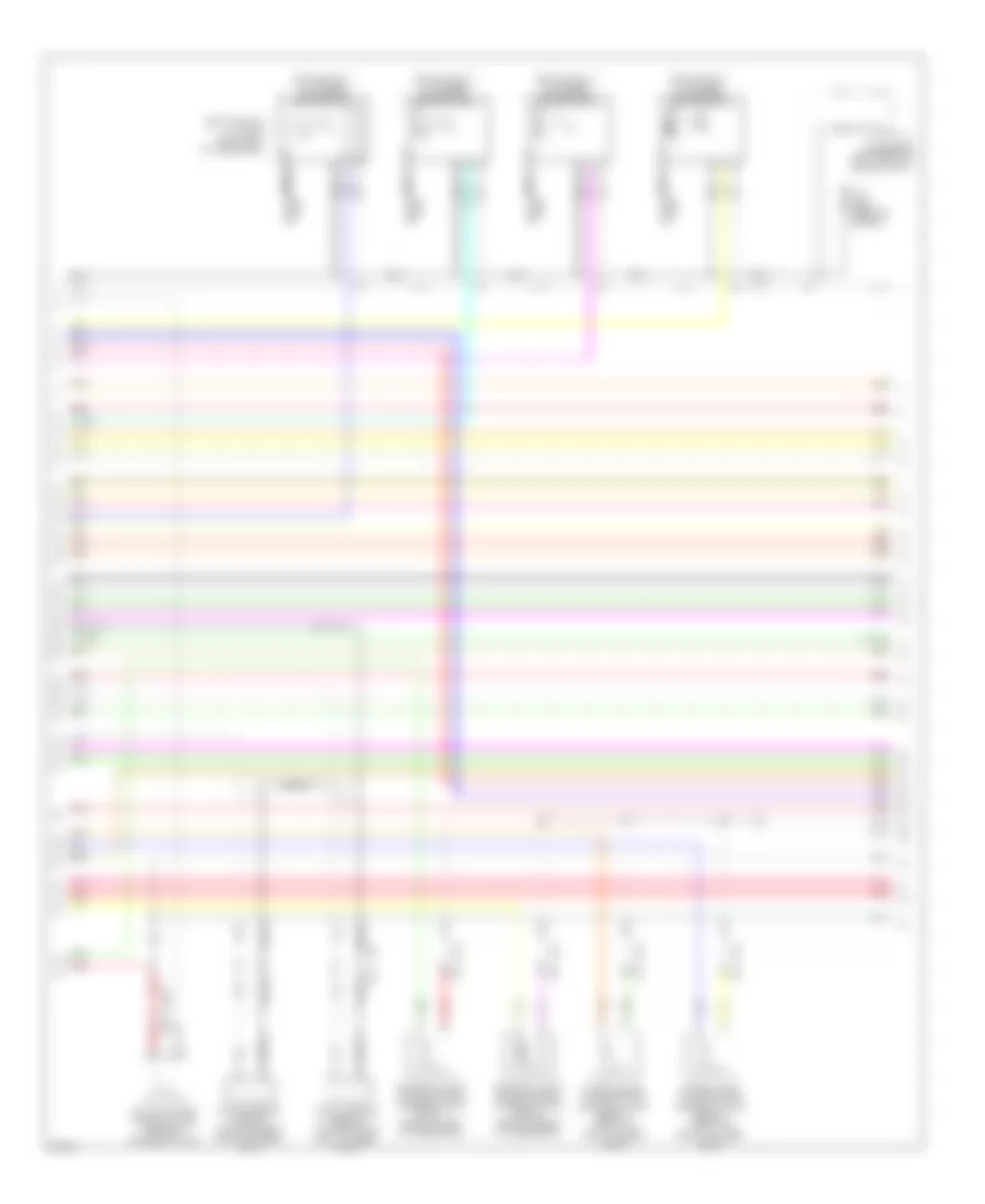
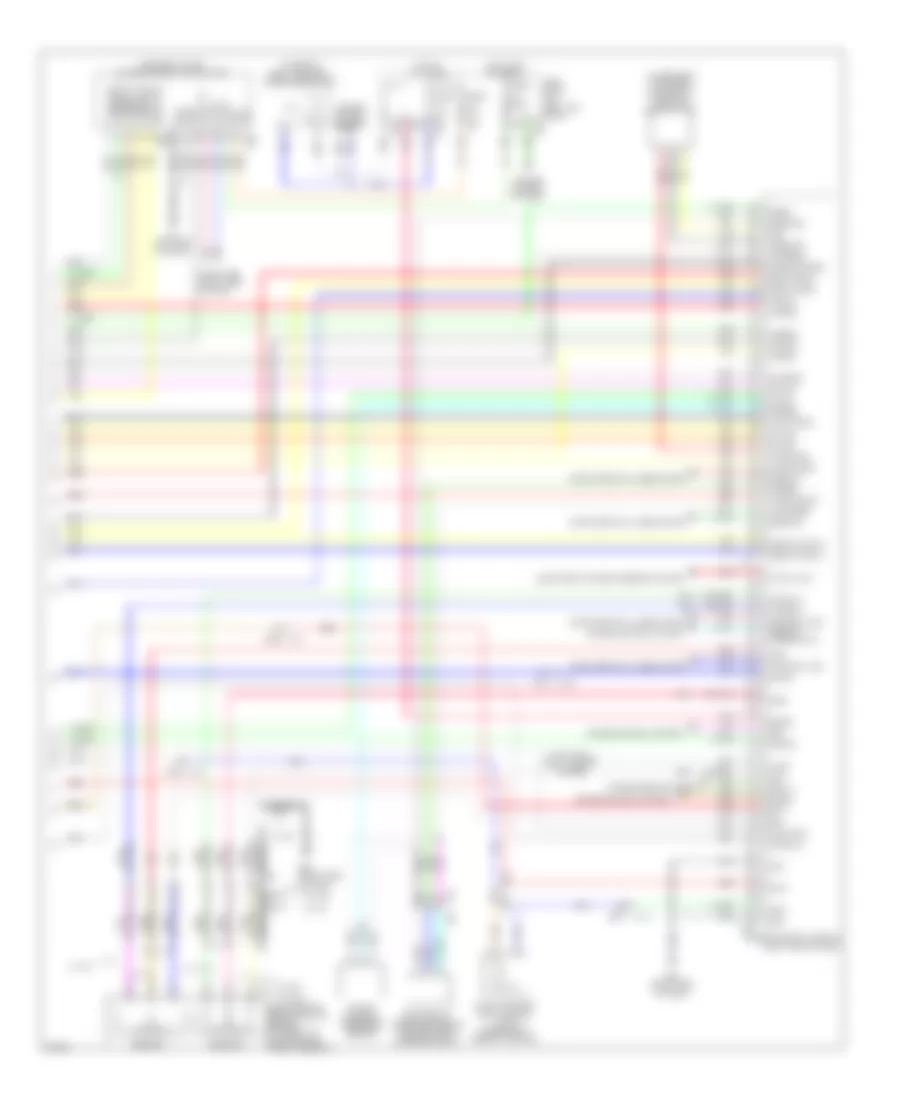
5.0L, Engine Performance Wiring Diagram (1 of 6) for Infiniti FX50 2012

List of elements for 5.0L, Engine Performance Wiring Diagram (1 of 6) for Infiniti FX50 2012:
- (ignition coils 2, 4, 6 & 8: top of right cylinder bank)
- A/f snsr
- Afh-b1
- Afh-b2
- Camshaft position sensor (bank 1) (front of left cylinder bank)
- Camshaft position sensor (bank 2) (front of right cylinder bank)
- E10
- Ect senr
- Engine control module (ecm) (right end of dash)
- Evap
- Ex cvtc-b1
- Ex cvtc-b2
- Ex phase-b1
- Ex phase-b2
- Exhaust valve timing control position sensor (bank 1) (front of left cylinder bank)
- Exhaust valve timing control position sensor (bank 2) (front of right cylinder bank)
- F10
- F103
- F110
- F111
- Gnd
- Ign 1
- Ign 2
- Ign 3
- Ign 4
- Ign 5
- Ign 6
- Ign 7
- Ign 8
- Ignition coil 2 (w/ power transistor)
- Ignition coil 4 (w/ power transistor)
- Ignition coil 6 (w/ power transistor)
- Ignition coil 8 (w/ power transistor)
- In cvtc-b1
- In cvtc-b2
- Inj 1
- Inj 2
- Inj 3
- Inj 4
- Inj 5
- Inj 6
- Inj 7
- Inj 8
- Intake air temp
- Intake air temp sensor
- Knk1
- Knk2
- M116
- M95 (right side of dash)
- Mass air flow (maf) sensor (bank 1) (left front of engine compt)
- Mass air flow (maf) sensor (bank 2) (right front of engine compt)
- Mot rly
- Motor1-b1
- Motor1-b2
- Motor2-b1
- Motor2-b2
- Nca
- O2hr-b1
- O2hr-b2
- O2sr-b1
- O2sr-b2
- Oil temp
- Plug spark
- Pnk
- Pos snsr
- Pos snsr 2
- Red
- Spark plug
- Ssoff
- Tan
- Vmot-b1
- Vmot-b2
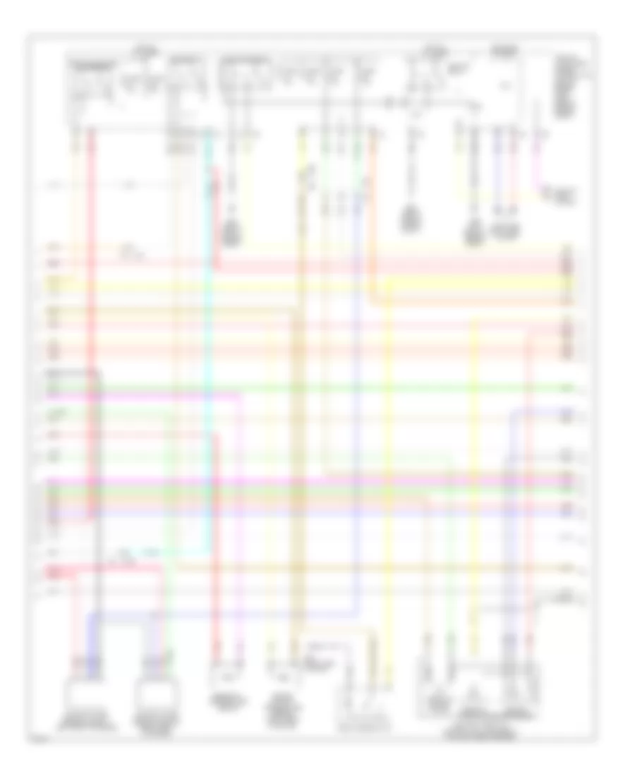
5.0L, Engine Performance Wiring Diagram (2 of 6) for Infiniti FX50 2012
List of elements for 5.0L, Engine Performance Wiring Diagram (2 of 6) for Infiniti FX50 2012:
- (ignition coils 1, 3, 5 & 7: top of left cylinder bank)
- Condenser (left front of engine compt)
- E10 f10
- Evap canister purge volume control solenoid valve
- Exhaust valve timing control solenoid valve (bank 1) (front of left cylinder bank)
- Exhaust valve timing control solenoid valve (bank 2) (front of right cylinder bank)
- F103
- F34 (left front of engine)
- F49 f211
- Ignition coil 1 (w/ power transistor)
- Ignition coil 3 (w/ power transistor)
- Ignition coil 5 (w/ power transistor)
- Ignition coil 7 (w/ power transistor)
- Intake valve timing control solenoid valve (bank 1) (front of left cylinder bank)
- Intake valve timing control solenoid valve (bank 2) (front of right cylinder bank)
- Knock sensor (bank 1) (top center of left cylinder bank)
- Knock sensor (bank 2) (top center of right cylinder bank)
- M116
- Nca
- Plug spark
- Pnk
- Red
- Shield
- Spark plug
- Tan
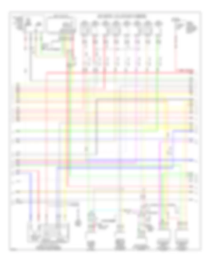
5.0L, Engine Performance Wiring Diagram (3 of 6) for Infiniti FX50 2012
List of elements for 5.0L, Engine Performance Wiring Diagram (3 of 6) for Infiniti FX50 2012:
- Close
- Computer data lines system
- Cooling fans system
- Cpu
- E10
- E106
- E106 m6
- E22 (right side of engine compt)
- E46 (left rear of engine compt)
- Ecm relay
- Electric throttle control actuator (bank 1) (top left side of engine)
- Engine coolant temperature sensor (right rear of engine)
- Engine oil temperature sensor
- F10
- F10 e10
- Fuel pump relay
- Fuse 10a
- Fuse 15a
- Heated oxygen sensor 2 (bank 1) (left front of engine)
- Heated oxygen sensor 2 (bank 2) (right front of engine)
- Hot at all times
- Hot in on or start
- Ignition relay
- Ipdm e/r (intelligent power distribution module engine room) (right rear of engine compt)
- M95 (right side of dash)
- Open
- Pnk
- Red
- Sensor 1
- Sensor 2
- Shield
- Snow mode switch
- Tan
- Throttle control motor
- Throttle control motor relay
- Throttle position sensor
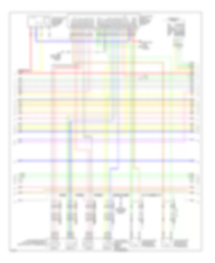
5.0L, Engine Performance Wiring Diagram (4 of 6) for Infiniti FX50 2012
List of elements for 5.0L, Engine Performance Wiring Diagram (4 of 6) for Infiniti FX50 2012:
- (fuel injector 1, 3, 5 & 7: top of left cylinder bank) (fuel injector 2, 4, 6 & 8: top of right cylinder bank)
- (left "c" pillar) b24
- (left "c" pillar) fuel pump control module
- Air fuel ratio (a/f) sensor 1 (bank 1) (right rear of engine)
- Air fuel ratio (a/f) sensor 1 (bank 2) (left rear of engine)
- B201 m95 (right side of dash)
- Bat
- Battery current sensor (on battery)
- Close
- Diag out sig
- E10
- E121
- Electric throttle control actuator (bank 2) (top right side of engine)
- Evap control system pressure sensor
- F10
- F103
- F121 f60
- F122 f69
- Fpc in sig
- Fuel injector
- Fuel level sensor unit & fuel pump (main) (in fuel tank)
- Fuel pump
- Fuel pump +
- Fuel pump -
- Fuel tank temp sensor
- Fuse & fusible link block (right rear of engine compt)
- Fusible link g 50a
- Gnd
- Hot at all times
- M116
- M117
- M95 (right side of dash)
- Manifold absolute pressure sensor (top center of engine)
- Open
- Pnk
- Red
- Sensor 1
- Sensor 2
- Shield
- Throttle control motor
- Throttle position sensor
5.0L, Engine Performance Wiring Diagram (5 of 6) for Infiniti FX50 2012
List of elements for 5.0L, Engine Performance Wiring Diagram (5 of 6) for Infiniti FX50 2012:
- Combination meter
- Comm line
- Comm-amp->lcd
- Comm-amp->mtr
- Comm-lcd->amp
- Comm-mtr->amp
- Computer data lines system
- E10
- E22 (right side of engine compt)
- F10
- Lamp
- M-rly
- Malfunction indicator
- Mod gnd
- Motor b1
- Motor1-b2
- Motor2-b1
- Motor2-b2
- Mtr rly sig
- Pwr sply
- Red
- Sensor 1
- Sensor 2
- Shield
- Snsr gnd
- Vel/s-b1
- Vel/s-b2
- Vel/s2-b1
- Vel/s2-b2
- Vmot-b1
- Vmot-b2
- Vvel actuator motor (bank 1) (rear of left cylinder bank)
- Vvel actuator motor (bank 2) (rear of right cylinder bank)
- Vvel actuator motor relay (right rear of engine compt)
- Vvel control module (right rear of engine compt)
- Vvel control shaft position sensor (bank 1) (rear of left cylinder bank)
- Vvel control shaft position sensor (bank 2) (rear of right cylinder bank)
5.0L, Engine Performance Wiring Diagram (6 of 6) for Infiniti FX50 2012
List of elements for 5.0L, Engine Performance Wiring Diagram (6 of 6) for Infiniti FX50 2012:
- (center of dash) unified meter & a/c amplifier
- (lower rear of engine) crankshaft position sensor (pos)
- (on brake pedal bracket) stop lamp switch
- Abort
- Accelerator pedal position sensor (integral to accelerator pedal assembly)
- Af(+)-b1
- Af(+)-b2
- Af(-)-b1
- Af(-)-b2
- Aps1
- Aps2
- Avcc-phs-b2
- Avcc-pres
- Avcc-tps-b1
- Avcc2-phs-b1
- Avcc2-pos
- B201 m117
- Bat
- Batt
- Bncsw
- Brake
- Can comm line
- Can comm line ascd/icc steering sw
- Can-h
- Can-l
- Cdcv
- Comm-amp
- Comm-lcd
- Comm-mtr
- Computer data lines system
- Cruise control system
- Cursen
- E10
- E103
- E106
- Electronic power steering system
- Engcan-h
- Engcan-l
- Engine control module (right end of dash)
- Evap canister vent control valve (under right rear of vehicle)
- Evapprs
- F10
- F103 m116
- F111
- Fpcm
- Fpcmck
- Fuel lvl
- Fuel pump
- Fuse 10a
- Fuse block (j/b) (left kick panel)
- Gnd
- Gnda-evapprs
- Gnda-tps-b1
- Gnda-tps-b2
- Hot at all times
- Hot in on or start
- Ign
- Ign sw
- Intpress
- Kline
- M11 (left end of dash)
- M117 b201
- M160
- M6 e106
- M66
- M67
- M95 (right side of dash)
- Neut-h
- Output sig
- Pdpres
- Pnk
- Pos
- Power steering pressure sensor
- Pspres
- Pwr sply
- Red
- Refrigerant pressure sensor (center front of engine compt)
- Sensor 1
- Sensor 2
- Shield
- Snow sw
- Snsr gnd
- Snsr pwr sply
- Tps1-b1
- Tps1-b2
- Tps2-b1
- Tps2-b2
- Transmissions system
- W/ icc
- W/o icc