ENGINE PERFORMANCE
2.5L
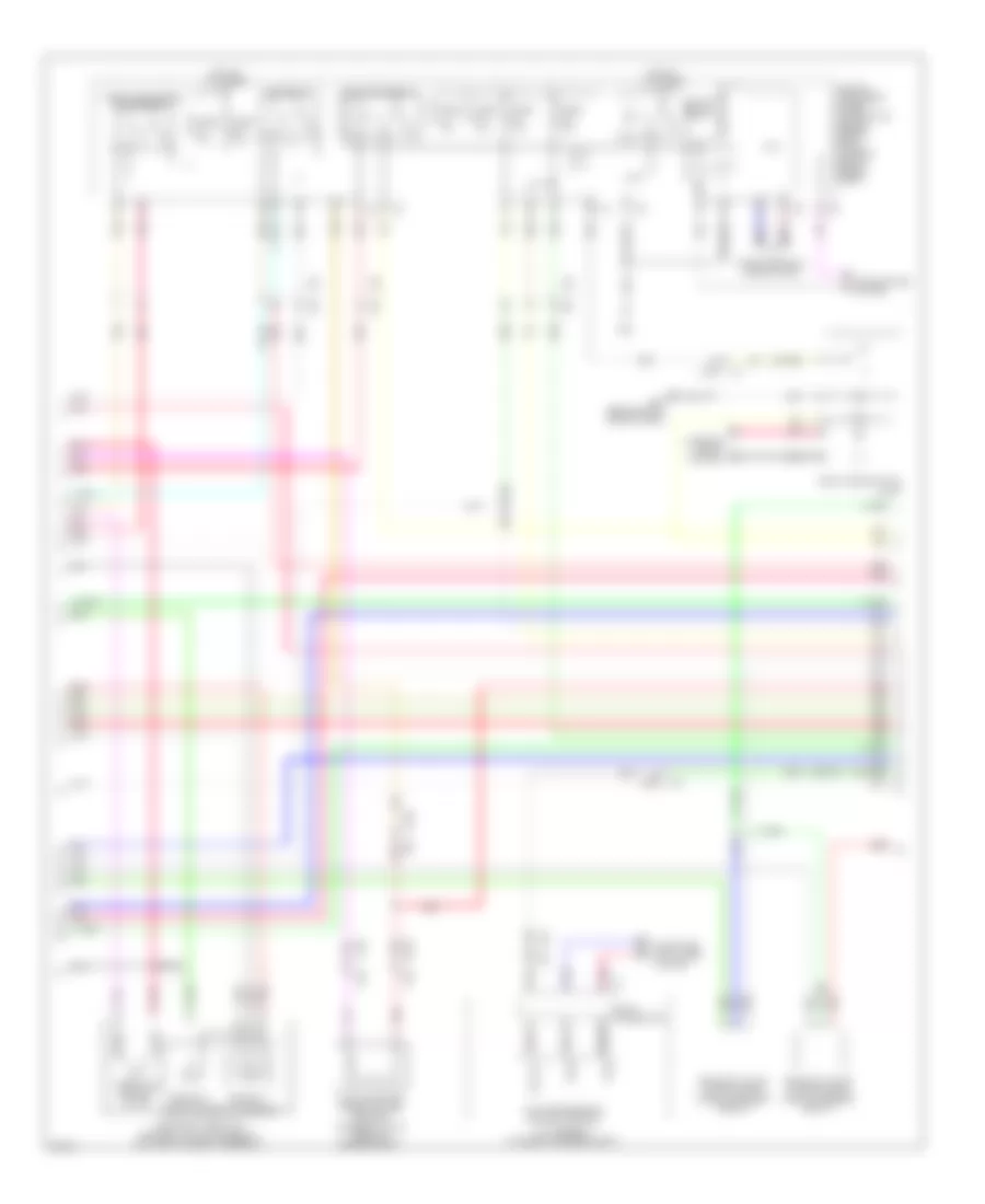
2.5L, Engine Performance Wiring Diagram (1 of 5) for Infiniti G25 Journey 2012

List of elements for 2.5L, Engine Performance Wiring Diagram (1 of 5) for Infiniti G25 Journey 2012:
- (1, 3 & 5: top of cylinder bank 1) (2, 4 & 6: top of cylinder bank 2)
- Af+1
- Af-1
- Afh1
- Afh2
- Avcc-phase 1
- Avcc-phase 2
- Avcc-pos
- Avcc-tps-b1
- Avcc-tps-b2
- Close
- Computer data lines system
- Condenser (right rear of engine)
- Crankshaft position sensor (pos) (right rear of engine)
- Cvt 2
- Cvtc 1
- E-phase 1
- E-phase 2
- Ecm (engine control module) (under right end of dash)
- Electric throttle control actuator (bank 2) (on throttle body assembly)
- Eng can-h1
- Eng can-l1
- Evap
- Evtc 1
- Evtc 2
- Exhaust valve timing control magnet retardar (bank 1) (right front of engine)
- Exhaust valve timing control magnet retardar (bank 2) (left front of engine)
- F101
- F102
- F104
- F104 f105
- F105
- F34 (right front of engine)
- Fpr
- Gnd
- Gnd-pos
- Gnda-tps-b1
- Gnda-tps-b2
- Ign 1
- Ign 2
- Ign 3
- Ign 4
- Ign 5
- Ign 6
- Ignition coil 1 (w/ power transistor)
- Ignition coil 2 (w/ power transistor)
- Ignition coil 3 (w/ power transistor)
- Ignition coil 4 (w/ power transistor)
- Ignition coil 5 (w/ power transistor)
- Ignition coil 6 (w/ power transistor)
- Ignsw
- Intake valve timing control solenoid valve (bank 1) (front of cylinder bank 1)
- Intake valve timing control solenoid valve (bank 2) (front of cylinder bank 2)
- M95 (behind right side of dash)
- Motarly1
- Motor1-b1
- Motor1-b2
- Motor2-b1
- Motor2-b2
- Nca
- O2hr1
- O2hr2
- Open
- Phase 1
- Phase 2
- Pnk
- Pos
- Red
- Sensor 1
- Sensor 2
- Spark plug
- Ssoff
- Tan
- Throttle control motor
- Throttle position sensor
- Tps 2-b1
- Tps 2-b2
- Tps1-b1
- Tps1-b2
- Vmot-b2
- Vmot1-b1
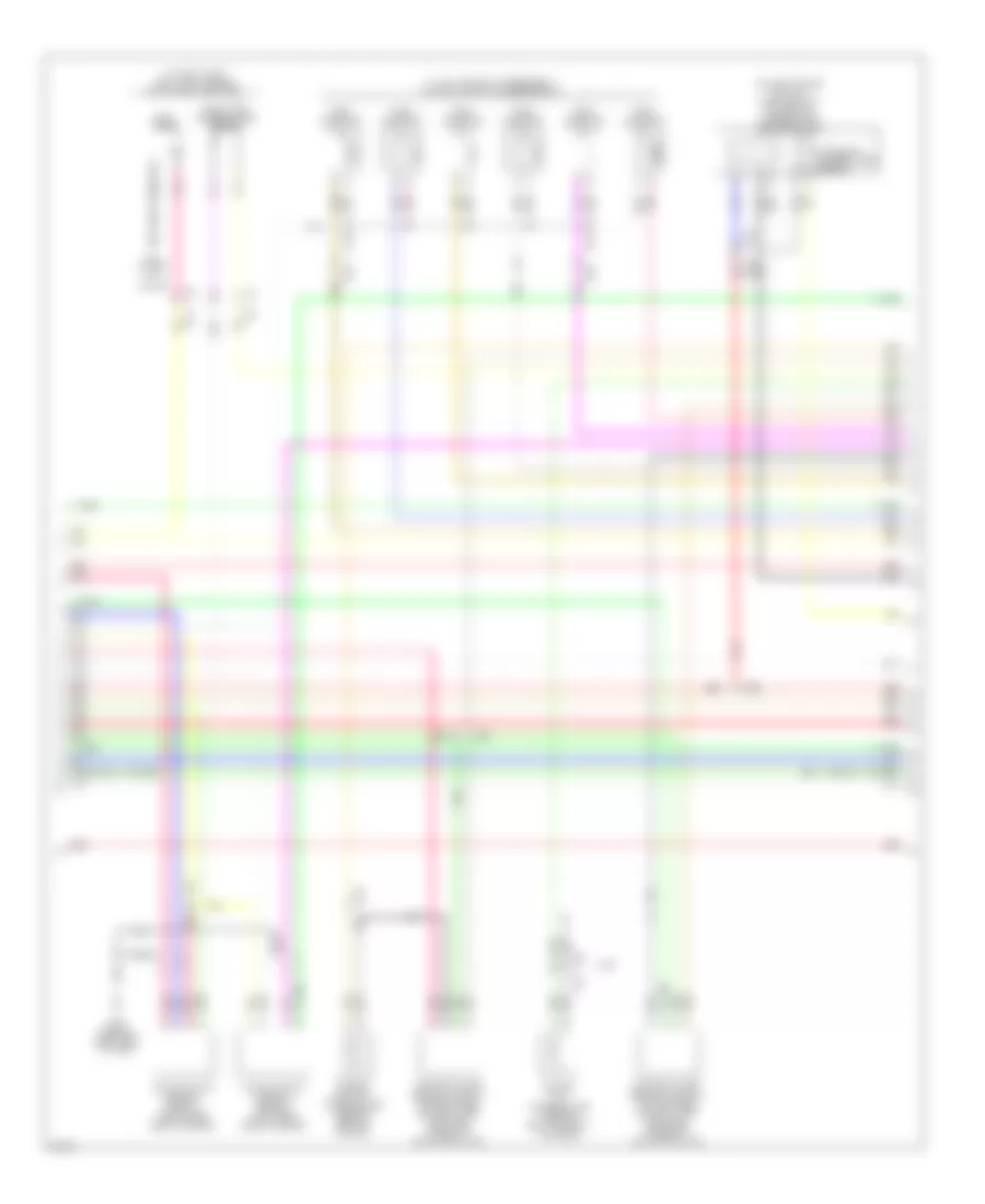
2.5L, Engine Performance Wiring Diagram (2 of 5) for Infiniti G25 Journey 2012
List of elements for 2.5L, Engine Performance Wiring Diagram (2 of 5) for Infiniti G25 Journey 2012:
- (awd)
- (or red)
- A/t assembly (at rear of engine compt)
- Can-h
- Can-l
- Close
- Computer data lines system
- Cooling fans system
- Cpu
- E106
- E22
- E25 f30
- Ecm relay
- Electric throttle control actuator (bank 1) (on throttle body assembly)
- Evap canister purge volume control solenoid valve (rear of engine compt)
- Exhaust valve timing control position sensor (bank 1)
- Exhaust valve timing control position sensor (bank 2)
- F103
- F104
- F105
- F51
- Fuel pump relay
- Fuse 10a
- Fuse 15a
- Hot at all times
- Ignition relay
- Ill
- Ind
- Interior lights system
- Ipdm e/r intelligent power distribution module (engine room) (at right rear of engine compt)
- Joint connector
- M116
- M95 (behind right side of dash)
- Nca
- Open
- Pnk
- Red
- Sensor 1
- Sensor 2
- Snow mode switch
- Str rly
- Tan
- Tcm (transmission control module)
- Throttle control motor
- Throttle control motor relay
- Throttle position sensor
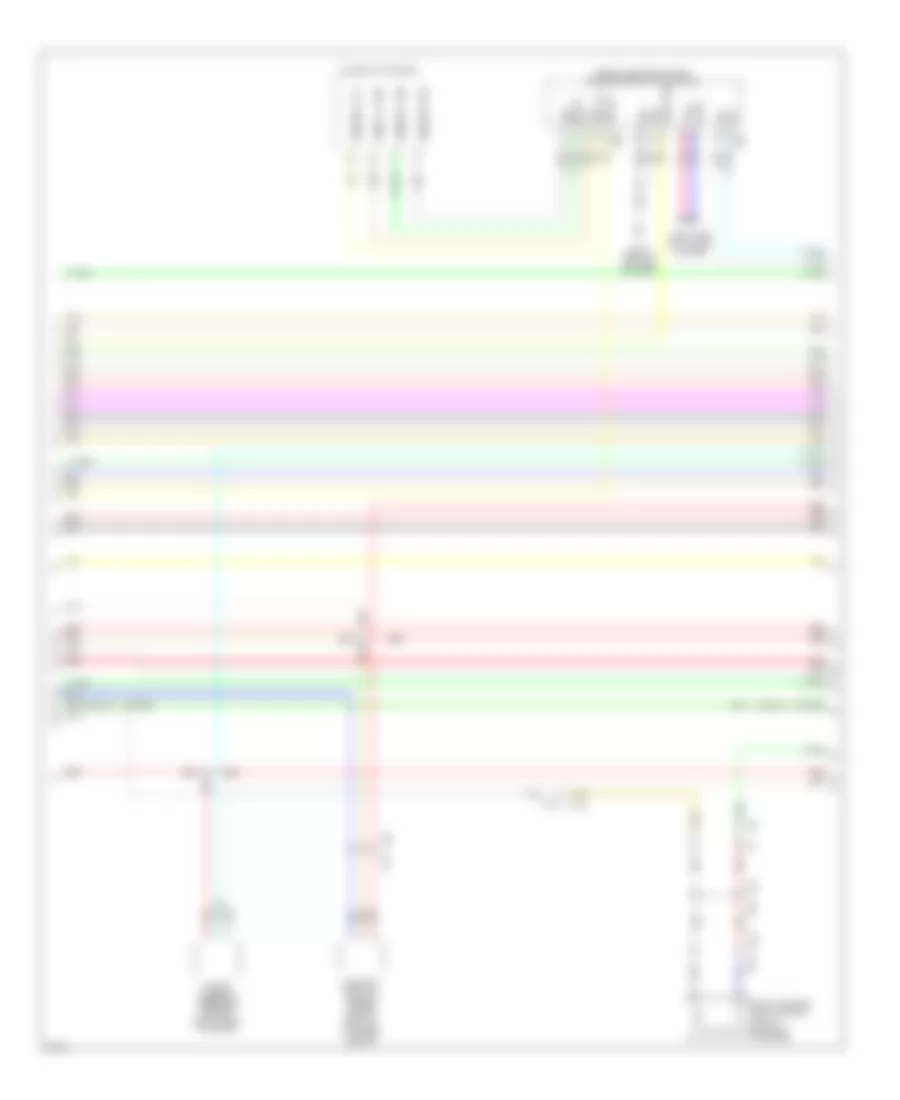
2.5L, Engine Performance Wiring Diagram (3 of 5) for Infiniti G25 Journey 2012
List of elements for 2.5L, Engine Performance Wiring Diagram (3 of 5) for Infiniti G25 Journey 2012:
- (1, 3 & 5: top of cylinder bank 1) (2, 4 & 6: top of cylinder bank 2)
- (at fuel tank) fuel level sensor unit & fuel pump (main)
- (on left intake air duct) mass airflow/ intake air temperature sensor (bank2)
- (or red)
- 2wd
- Air fuel ratio sensor 1 (bank 1) (right rear side of engine)
- Air fuel ratio sensor 1 (bank 2) (left rear side of engine)
- B24 (in left "c" pillar)
- E117
- Engine coolant temperature sensor (rear of engine)
- Engine oil temperature sensor (bottom front of engine)
- F103 m116
- F106
- F107
- F61 f251
- Fuel injector
- Fuel pump
- Fuel tank temperature sensor
- Heated oxygen sensor 2 (bank 1) (on right side exhaust pipe, between three-way catalysts 1 & 2)
- Heated oxygen sensor 2 (bank 2) (on left side exhaust pipe, between three-way catalysts 1 & 2)
- Intake air temperature sensor
- M95 (behind right side of dash)
- Nca
- Pnk
- Red
- Red pnk
- Tan
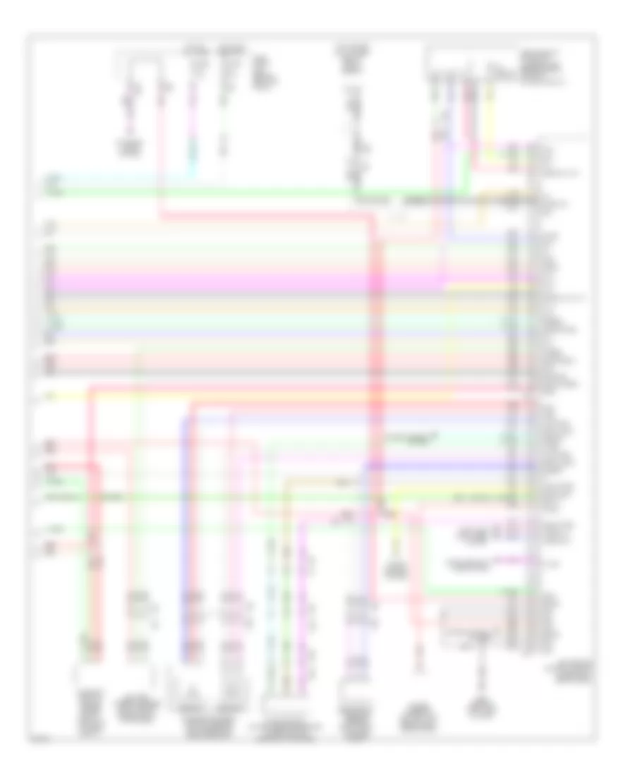
2.5L, Engine Performance Wiring Diagram (4 of 5) for Infiniti G25 Journey 2012
List of elements for 2.5L, Engine Performance Wiring Diagram (4 of 5) for Infiniti G25 Journey 2012:
- (behind center of dash) unified meter & a/c amplifier
- (or red)
- Amp
- Amp lcd
- B332 b254
- B39 b331
- Bat
- Camshaft position sensor (phase) (bank 2) (front of cylinder bank 2)
- Can-h
- Can-l
- Combination meter
- Comm-amp->lcd
- Comm-amp->mtr
- Comm-lcd->amp
- Comm-mtr->amp
- Computer data lines system
- Evap canister vent control valve (on evap canister)
- F103
- F106 f107
- Gnd
- Ign
- Lcd
- M11 (behind left end of dash)
- M116
- M66
- M67
- Meter
- Pnk
- Power steering pressure sensor (right front of engine)
- Red
- Red red
- Sens gnd
- Sw sig
- Tan
2.5L, Engine Performance Wiring Diagram (5 of 5) for Infiniti G25 Journey 2012
List of elements for 2.5L, Engine Performance Wiring Diagram (5 of 5) for Infiniti G25 Journey 2012:
- (or red)
- (top center of cylinder bank 1) knock sensor
- Accelerator pedal position sensor (on accelerator pedal bracket)
- Af+2
- Af-2
- Aps1
- Aps2
- Ascdsw
- Avcc-aps1
- Avcc-aps2
- Avcc-ftprs
- B332 b254
- B39 b331
- Batt
- Battery current sensor (right rear of engine compt, at battery)
- Bncsw
- Brake
- Camshaft position sensor (phase) (bank 1) (front of cylinder bank 1)
- Cdcv
- Computer data lines system
- Cruise control system
- Cursen
- E103
- E106
- E25
- Ecm (engine control module) (under right end of dash)
- Evap control system pressure sensor (under vehicle, near evap canister)
- Exterior lights system
- F102
- F103 m116
- F205
- F30
- F65
- Ftprs
- Fuse 10a
- Fuse block (j/b) (behind left kick panel)
- Gnd
- Gnd-a (aps1)
- Gnd-a (aps2)
- Gnd-e-phase
- Gnd-phase 2
- Gnda
- Gnda-ascd
- Gnda-cursen
- Gnda-ftprs
- Gnda-knk
- Gnda-o2_tw_to
- Gnda-qa1_ta1
- Gnda-qa2
- Hot at all times
- Hot in on or start
- Iat sensor
- Inj 1
- Inj 2
- Inj 3
- Inj 4
- Inj 5
- Inj 6
- K-line
- Knk
- M107
- M7 b1
- M95 (behind right side of dash)
- Mass airflow/ intake air temperature sensor (bank1) (on right intake air duct)
- Neut-h
- O2 sri
- O2sr2
- Pdpres
- Pnk
- Power steering control unit (behind right side of dash)
- Pspres
- Qa1+
- Qa2+
- Red
- Red red
- Refrigerant pressure sensor (right front of engine compt)
- Sensor 1
- Sensor 2
- Shield
- Ta 2
- Ta1
- Tacho
- Tan
- Vbr
- Vhecan_h1
- Vhecan_l1