ENGINE PERFORMANCE
3.5L
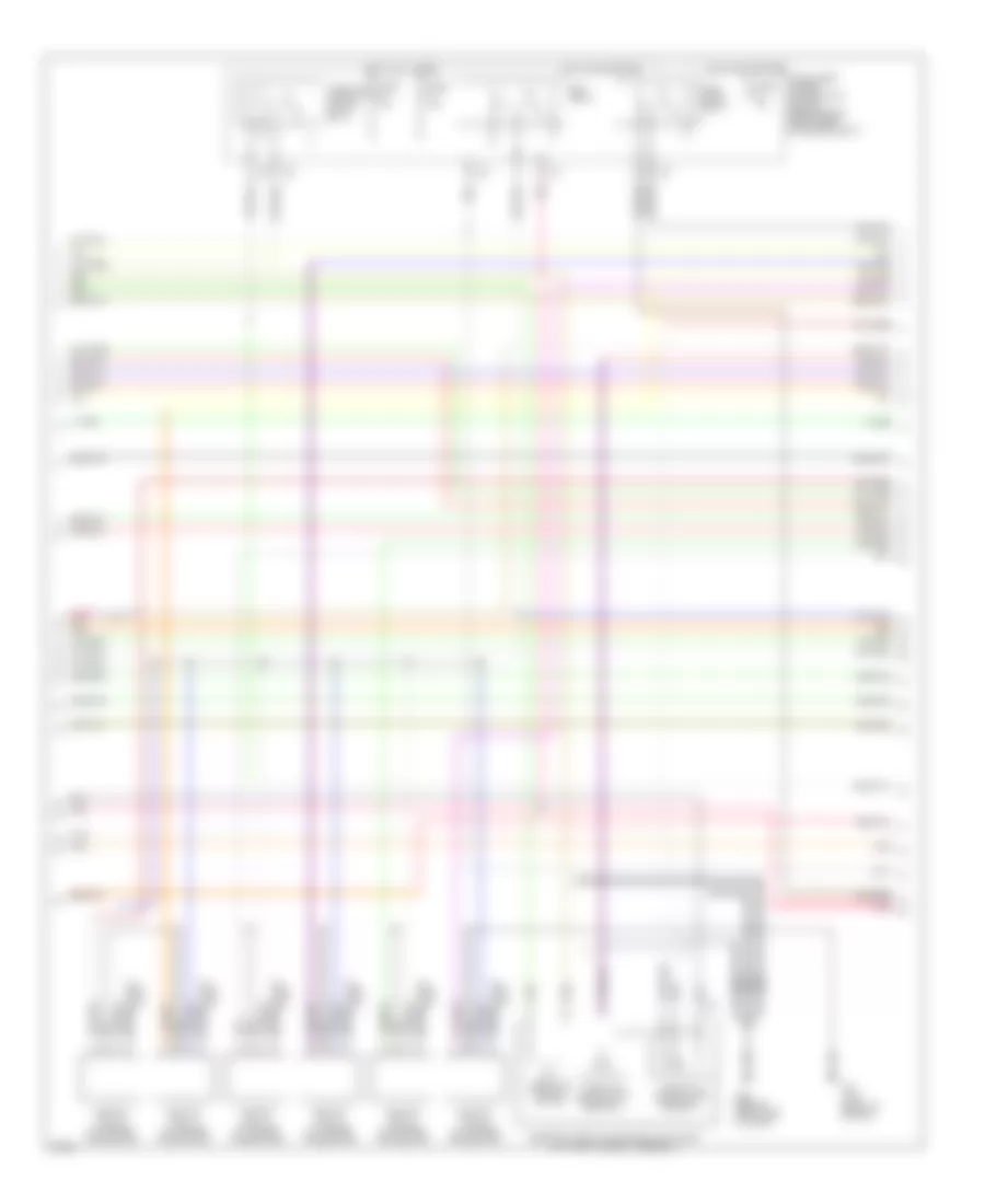
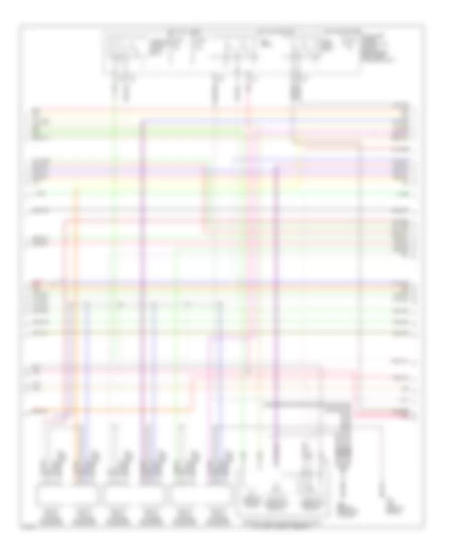
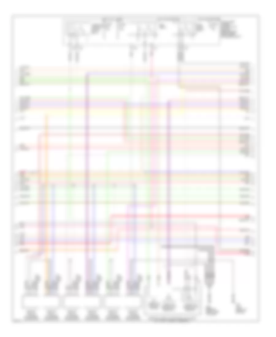
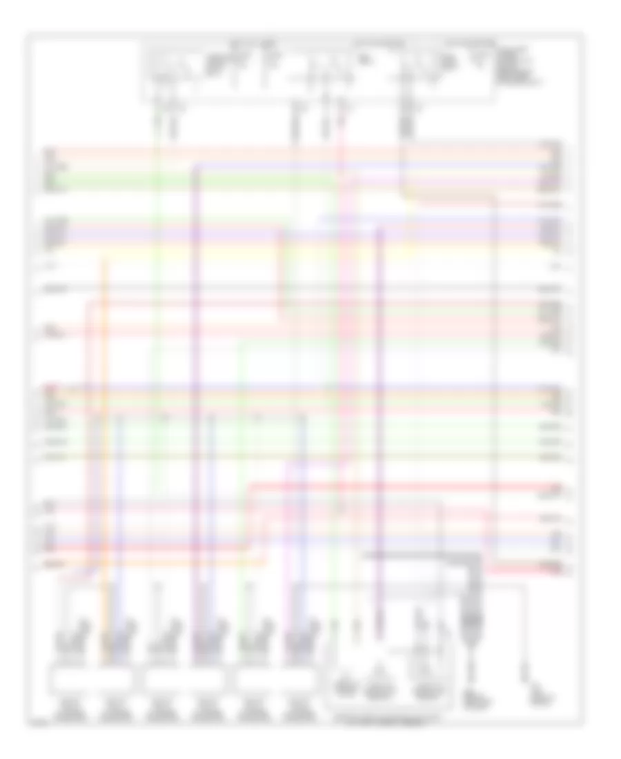
3.5L, Engine Performance Wiring Diagram, Early Production Coupe (1 of 4) for Infiniti G35 x 2004

List of elements for 3.5L, Engine Performance Wiring Diagram, Early Production Coupe (1 of 4) for Infiniti G35 x 2004:
- (behind right side of dash)
- Avcc
- Avcc2
- C-ivc (l)
- C-ivc (r)
- Combination meter
- Computer data lines system
- Condenser (right rear of engine)
- Crankshaft position sensor (pos) (on front of oil pan, below crankshaft pulley)
- Engine control module (behind right kick panel)
- Evap
- Evap canister purge volume control solenoid valve (on right side of intake manifold)
- F23 (top front of engine)
- Ftrps
- Fuel injector
- Fuse 10a
- Fuse block (j/b) (behind left kick panel)
- Gnd
- Hot in on or start
- Inj 1
- Inj 2
- Inj 3
- Inj 4
- Inj 5
- Inj 6
- Knk1
- Knock sensor (top center front of engine)
- M66
- M66 (behind right side of dash)
- Malfunction indicator lamp
- Motor1
- Motor2
- Nca
- Neutral
- O2hfl
- O2hfr
- O2hrl
- O2hrr
- O2sfl
- O2sfr
- O2srl
- Park/ neutral position switch (rear of trans- mission)
- Pdpres
- Phase lh
- Phase rh
- Pnk
- Pos
- Ps pres
- Qa+
- Red
- Refrigerant pressure sensor (on a/c liquid tank)
- Tps1
- Unified meter control unit
- V mot
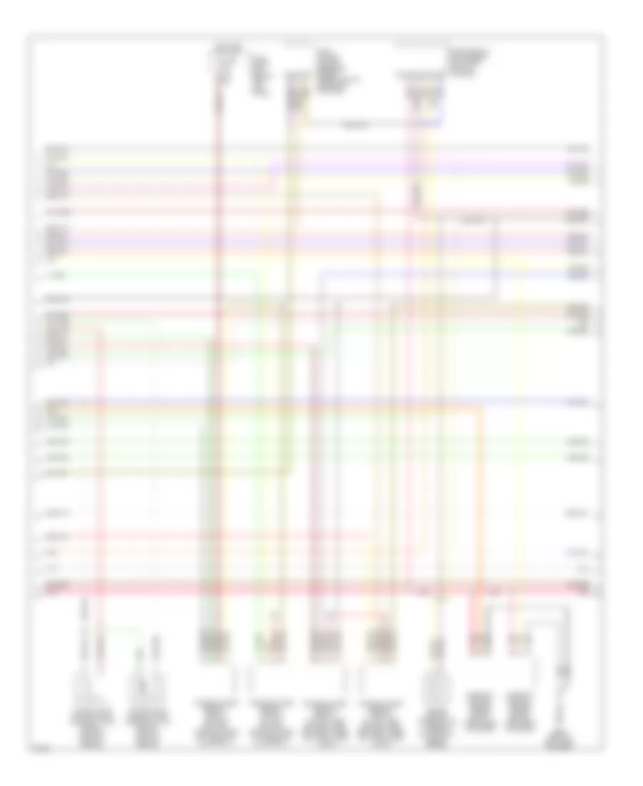
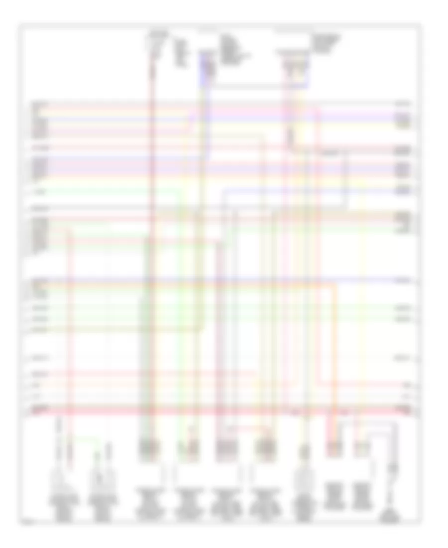
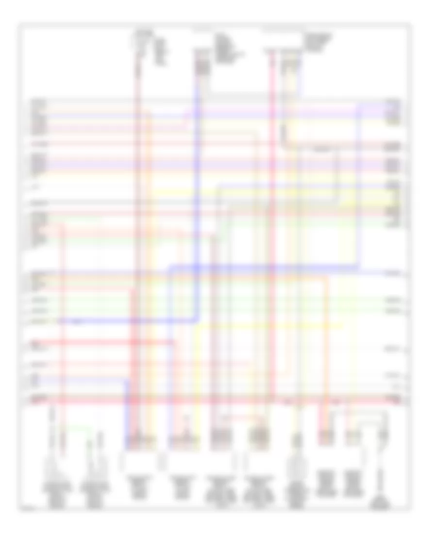
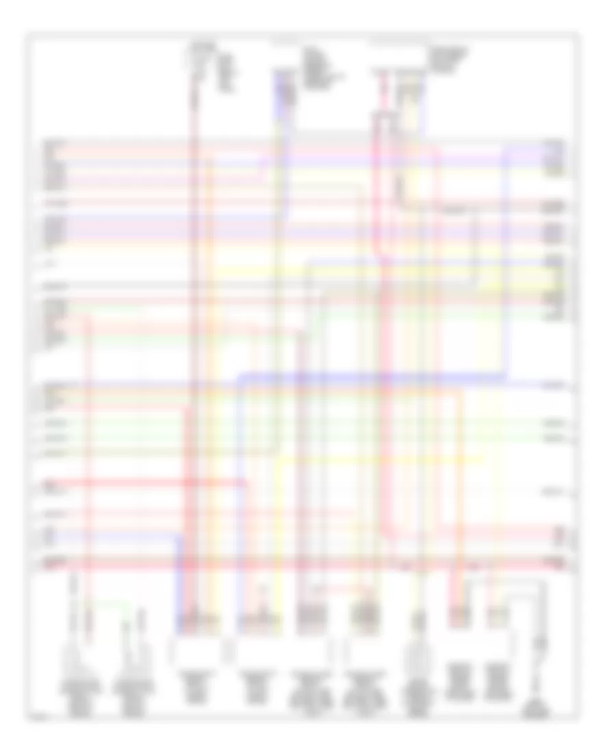
3.5L, Engine Performance Wiring Diagram, Early Production Coupe (2 of 4) for Infiniti G35 x 2004
List of elements for 3.5L, Engine Performance Wiring Diagram, Early Production Coupe (2 of 4) for Infiniti G35 x 2004:
- Ecm relay
- Electric throttle control actuator (on throttle body assembly)
- F23 (top front of engine)
- F31
- Fuel pump relay
- Fuse 15a
- Hot at all times
- Hot in on or start
- Ignition coil 1 (w/ power transistor)
- Ignition coil 2 (w/ power transistor)
- Ignition coil 3 (w/ power transistor)
- Ignition coil 4 (w/ power transistor)
- Ignition coil 5 (w/ power transistor)
- Ignition coil 6 (w/ power transistor)
- Intelligent power distribution module (engine room) (right rear of engine compt)
- M66 (behind right side of dash)
- Nca
- Nca nca
- Plug spark
- Pnk
- Spark plug
- Throttle control motor
- Throttle control motor relay
- Throttle position (tp) sensor 1
- Throttle position (tp) sensor 2
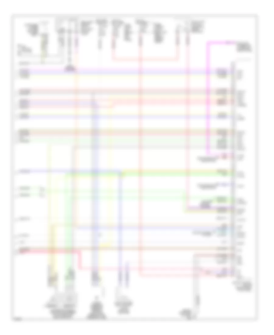
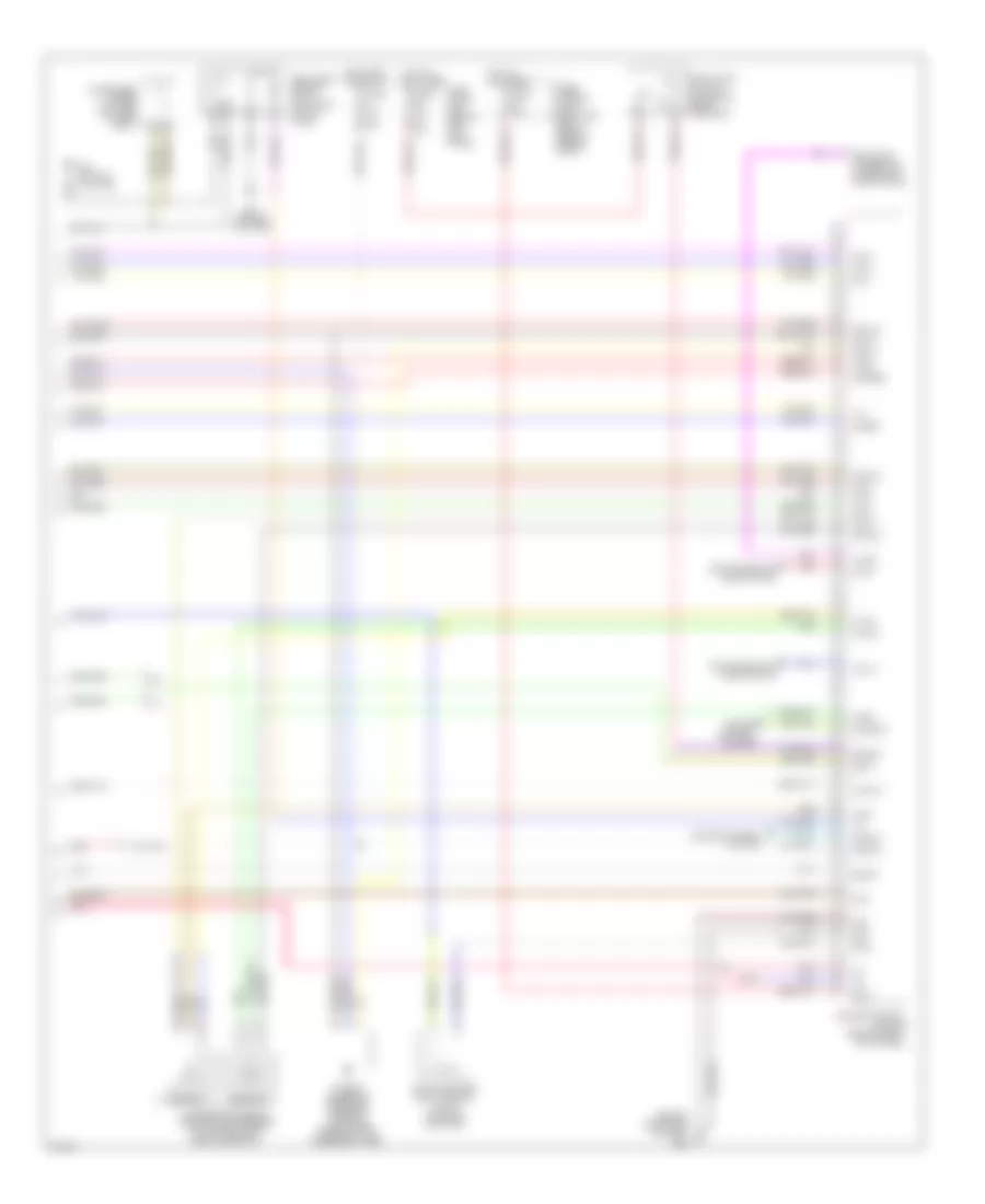
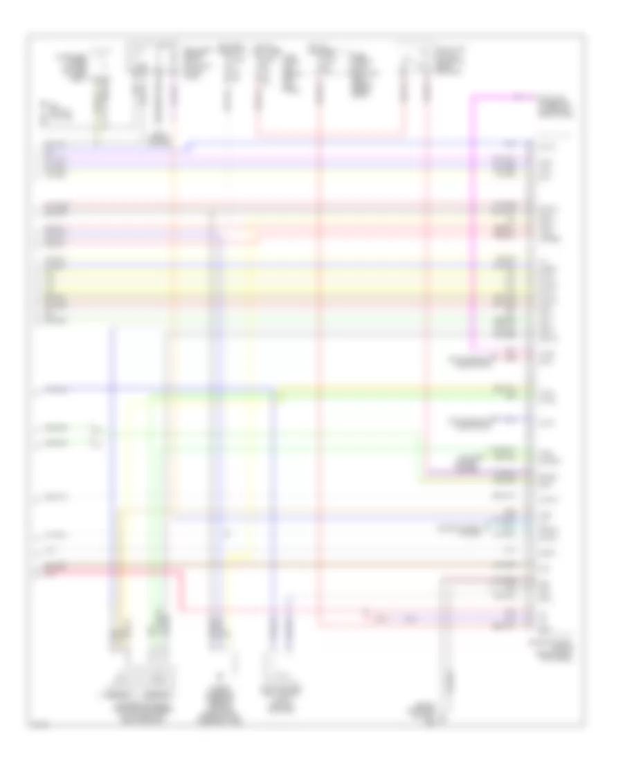
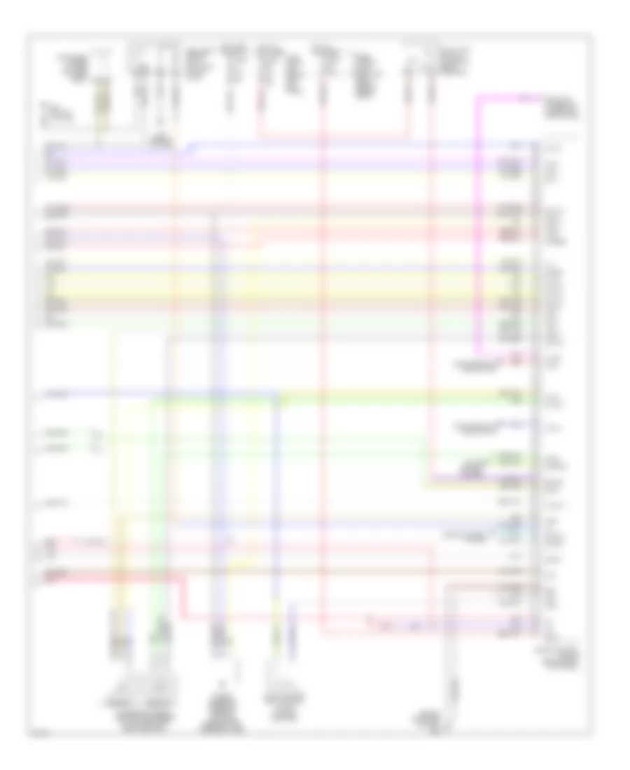
3.5L, Engine Performance Wiring Diagram, Early Production Coupe (3 of 4) for Infiniti G35 x 2004
List of elements for 3.5L, Engine Performance Wiring Diagram, Early Production Coupe (3 of 4) for Infiniti G35 x 2004:
- Camshaft position sensor (phase) (bank 1) (right rear of engine)
- Camshaft position sensor (phase) (bank 2) (left rear of engine)
- Engine coolant temperature sensor (on top right rear of engine)
- Evap control system pressure sensor (under vehicle, near evap canister)
- Fuse 15a
- Fuse block (j/b) (behind left kick panel)
- Heated oxygen sensor 1 (bank 1) (on right exhaust manifold, ahead of three way catalyst 1)
- Heated oxygen sensor 1 (bank 2) (on left exhaust manifold, ahead of three way catalyst 1)
- Heated oxygen sensor 2 (bank 1) (on right side exhaust pipe, between three way catalysts 1 and 2)
- Heated oxygen sensor 2 (bank 2) (on left side exhaust pipe, between three way catalysts 1 and 2)
- Hot in on or start
- Intake valve timing control solenoid valve (bank 1) (on right front of engine)
- Intake valve timing control solenoid valve (bank 2) (on left front of engine)
- M66 (behind right side of dash)
- Mass airflow (maf) sensor (on intake air duct housing)
- Pnk
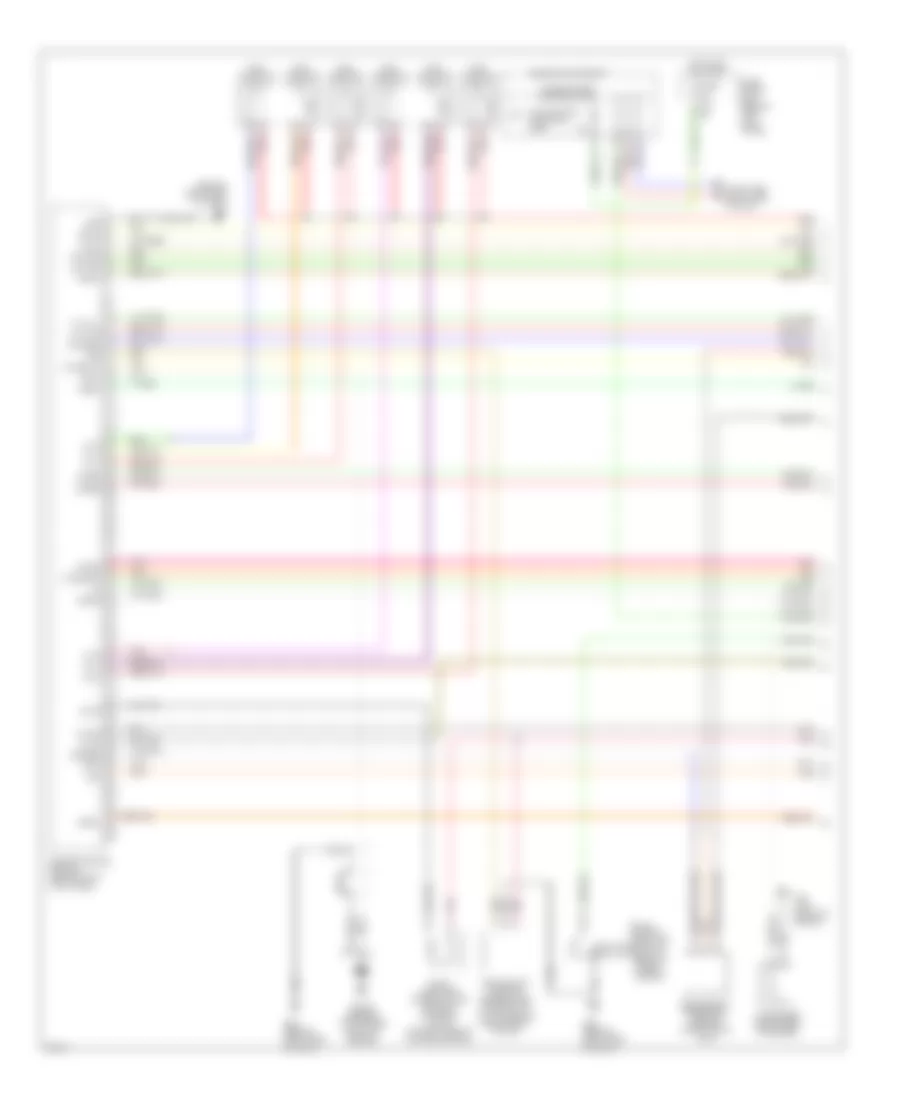
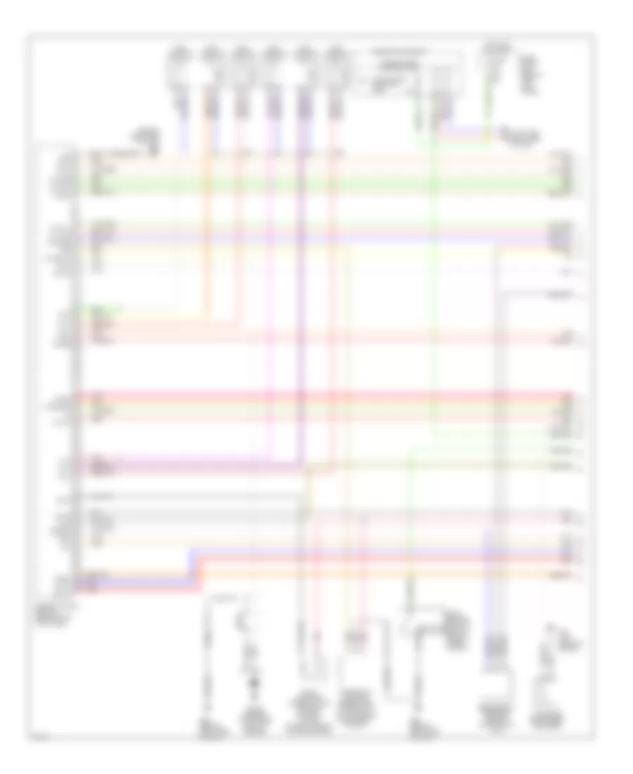
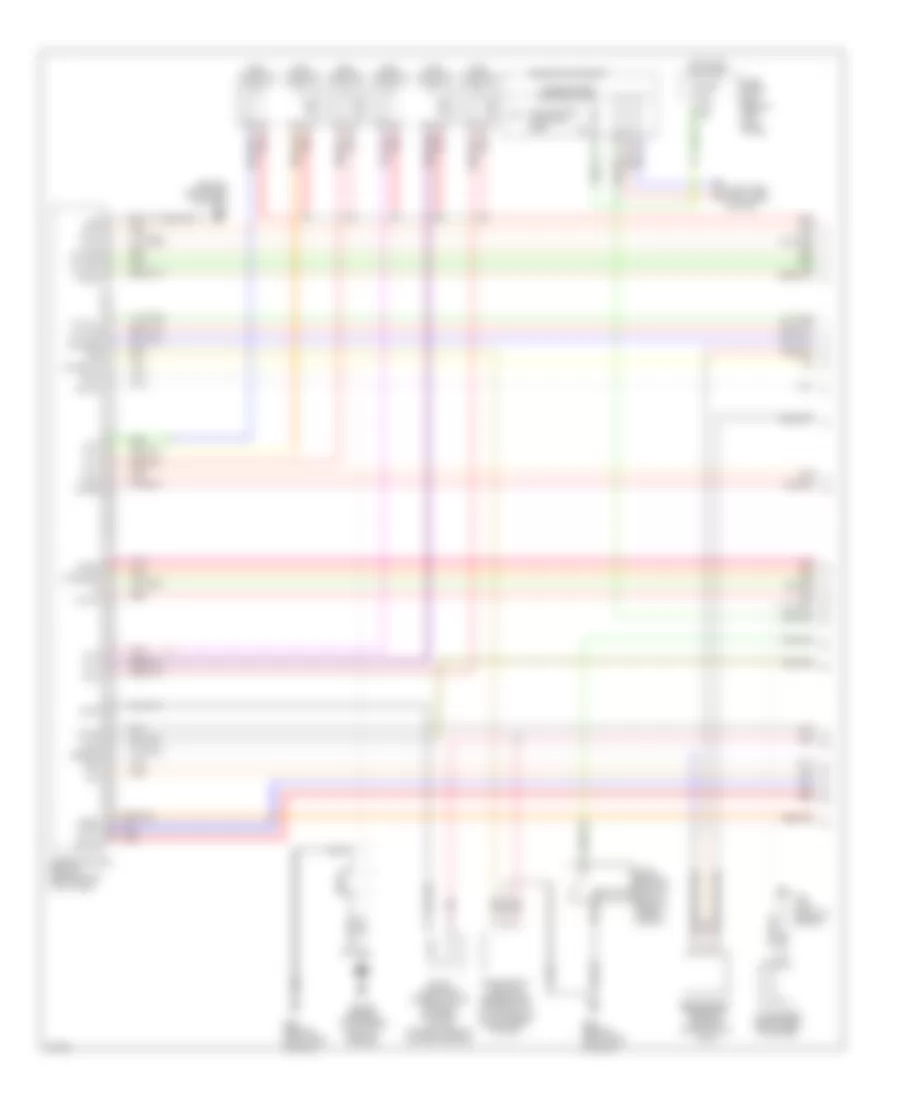
3.5L, Engine Performance Wiring Diagram, Early Production Coupe (4 of 4) for Infiniti G35 x 2004
List of elements for 3.5L, Engine Performance Wiring Diagram, Early Production Coupe (4 of 4) for Infiniti G35 x 2004:
- (behind right side of dash)
- 15a
- A/t
- Accelerator pedal position (app) sensor (on accelerator pedal bracket)
- Aps1
- Aps2
- Ascdsw
- Avcc
- Avcc2
- B29 (on left c pillar)
- Batt
- Bncsw
- Brake
- Can l
- Can-h
- Cdcv
- Computer data lines system
- Condenser (under left side of rear seat)
- Cruise control system
- Data link connector (lower left side of dash)
- E101
- Engine control module (behind right kick panel)
- Evap canister vent control valve (on evap canister)
- Fpr
- Fuel level sensor unit & fuel pump (in fuel tank)
- Fuse 10a
- Fuse 15a
- Fuse block (j/b) (behind left kick panel)
- Fuse, fusible link & relay box (right rear of engine compt)
- Gnd
- Gnd 02
- Gnd a
- Gnd a2
- Hot at all times
- Hot in on or start
- Ign 1
- Ign 2
- Ign 3
- Ign 4
- Ign 5
- Ign 6
- Ign sw
- Kline
- M/t
- M30 (behind cluster)
- M66
- Motrly
- Neut
- O2srr
- Pdpres
- Pnk
- Power steering pressure sensor (on power steering high pressure tube)
- Red
- Sensor 1
- Sensor 2
- Ssoff
- Stop lamp switch (on brake pedal bracket)
- Tps2
3.5L, Engine Performance Wiring Diagram, Early Production Sedan (1 of 4) for Infiniti G35 x 2004
List of elements for 3.5L, Engine Performance Wiring Diagram, Early Production Sedan (1 of 4) for Infiniti G35 x 2004:
- (behind right side of dash)
- Avcc
- Avcc2
- C-ivc (l)
- C-ivc (r)
- Combination meter
- Computer data lines system
- Condenser (right rear of engine)
- Crankshaft position sensor (pos) (on front of oil pan, below crankshaft pulley)
- Engine control module (behind right kick panel)
- Evap
- Evap canister purge volume control solenoid valve (on right side of intake manifold)
- F23 (top front of engine)
- Ftrps
- Fuel injector
- Fuse 10a
- Fuse block (j/b) (behind left kick panel)
- Gnd
- Hot in on or start
- Inj 1
- Inj 2
- Inj 3
- Inj 4
- Inj 5
- Inj 6
- Knk1
- Knock sensor (top center front of engine)
- M66
- M66 (behind right side of dash)
- Malfunction indicator lamp
- Motor1
- Motor2
- Nca
- Neutral
- O2hfl
- O2hfr
- O2hrl
- O2hrr
- O2sfl
- O2sfr
- O2srl
- Park/ neutral position switch (rear of trans- mission)
- Pdpres
- Phase lh
- Phase rh
- Pnk
- Pos
- Ps pres
- Qa+
- Red
- Refrigerant pressure sensor (on a/c liquid tank)
- Tps1
- Unified meter control unit
- V mot
3.5L, Engine Performance Wiring Diagram, Early Production Sedan (2 of 4) for Infiniti G35 x 2004
List of elements for 3.5L, Engine Performance Wiring Diagram, Early Production Sedan (2 of 4) for Infiniti G35 x 2004:
- Ecm relay
- Electric throttle control actuator (on throttle body assembly)
- F23 (top front of engine)
- F31
- Fuel pump relay
- Fuse 15a
- Hot at all times
- Hot in on or start
- Ignition coil 1 (w/ power transistor)
- Ignition coil 2 (w/ power transistor)
- Ignition coil 3 (w/ power transistor)
- Ignition coil 4 (w/ power transistor)
- Ignition coil 5 (w/ power transistor)
- Ignition coil 6 (w/ power transistor)
- Intelligent power distribution module (engine room) (right rear of engine compt)
- M66 (behind right side of dash)
- Nca
- Nca nca
- Plug spark
- Pnk
- Red
- Spark plug
- Throttle control motor
- Throttle control motor relay
- Throttle position (tp) sensor 1
- Throttle position (tp) sensor 2
3.5L, Engine Performance Wiring Diagram, Early Production Sedan (3 of 4) for Infiniti G35 x 2004
List of elements for 3.5L, Engine Performance Wiring Diagram, Early Production Sedan (3 of 4) for Infiniti G35 x 2004:
- Camshaft position sensor (phase) (bank 1) (right rear of engine)
- Camshaft position sensor (phase) (bank 2) (left rear of engine)
- Engine coolant temperature sensor (on top right rear of engine)
- Evap control system pressure sensor (under vehicle, near evap canister)
- Fuse 15a
- Fuse block (j/b) (behind left kick panel)
- Heated oxygen sensor 1 (bank 1) (on right exhaust manifold, ahead of three way catalyst 1)
- Heated oxygen sensor 1 (bank 2) (on left exhaust manifold, ahead of three way catalyst 1)
- Heated oxygen sensor 2 (bank 1) (on right side exhaust pipe, between three way catalysts 1 and 2)
- Heated oxygen sensor 2 (bank 2) (on left side exhaust pipe, between three way catalysts 1 and 2)
- Hot in on or start
- Intake valve timing control solenoid valve (bank 1) (on right front of engine)
- Intake valve timing control solenoid valve (bank 2) (on left front of engine)
- M66 (behind right side of dash)
- Mass airflow (maf) sensor (on intake air duct housing)
- Pnk
- Red
3.5L, Engine Performance Wiring Diagram, Early Production Sedan (4 of 4) for Infiniti G35 x 2004
List of elements for 3.5L, Engine Performance Wiring Diagram, Early Production Sedan (4 of 4) for Infiniti G35 x 2004:
- (behind right side of dash)
- 15a
- A/t
- Accelerator pedal position (app) sensor (on accelerator pedal bracket)
- Aps1
- Aps2
- Ascdsw
- Avcc
- Avcc2
- B29 (on left c pillar)
- Batt
- Bncsw
- Brake
- Can l
- Can-h
- Cdcv
- Computer data lines system
- Condenser (under left side of rear seat)
- Cruise control system
- Data link connector (lower left side of dash)
- E101
- Engine control module (behind right kick panel)
- Evap canister vent control valve (on evap canister)
- Fpr
- Fuel level sensor unit & fuel pump (in fuel tank)
- Fuse 10a
- Fuse 15a
- Fuse block (j/b) (behind left kick panel)
- Fuse, fusible link & relay box (right rear of engine compt)
- Gnd
- Gnd 02
- Gnd a
- Gnd a2
- Hot at all times
- Hot in on or start
- Ign 1
- Ign 2
- Ign 3
- Ign 4
- Ign 5
- Ign 6
- Ign sw
- Kline
- M/t
- M30 (behind cluster)
- M66
- Motrly
- Neut
- O2srr
- Pdpres
- Pnk
- Power steering pressure sensor (on power steering high pressure tube)
- Red
- Sensor 1
- Sensor 2
- Ssoff
- Stop lamp switch (on brake pedal bracket)
- Tps2
3.5L, Engine Performance Wiring Diagram, Late Production Coupe (1 of 4) for Infiniti G35 x 2004
List of elements for 3.5L, Engine Performance Wiring Diagram, Late Production Coupe (1 of 4) for Infiniti G35 x 2004:
- (behind right side of dash)
- Af-h1
- Af-h2
- Af-ip1
- Af-un1
- Af-vm1
- Avcc
- Avcc2
- C-ivc (l)
- C-ivc (r)
- Combination meter
- Computer data lines system
- Condenser (right rear of engine)
- Crankshaft position sensor (pos) (on front of oil pan, below crankshaft pulley)
- Engine control module (behind right kick panel)
- Evap
- Evap canister purge volume control solenoid valve (on right side of intake manifold)
- F23 (top front of engine)
- Ftrps
- Fuel injector
- Fuse 10a
- Fuse block (j/b) (behind left kick panel)
- Gnd
- Hot in on or start
- Inj 1
- Inj 2
- Inj 3
- Inj 4
- Inj 5
- Inj 6
- Knk1
- Knock sensor (top center front of engine)
- M66
- M66 (behind right side of dash)
- Malfunction indicator lamp
- Motor1
- Motor2
- Nca
- Neutral
- O2hrl
- O2hrr
- O2srl
- Park/ neutral position switch (rear of trans- mission)
- Pdpres
- Phase lh
- Phase rh
- Pnk
- Pos
- Ps pres
- Qa+
- Red
- Refrigerant pressure sensor (on a/c liquid tank)
- Tps1
- Unified meter control unit
- V mot
3.5L, Engine Performance Wiring Diagram, Late Production Coupe (2 of 4) for Infiniti G35 x 2004
List of elements for 3.5L, Engine Performance Wiring Diagram, Late Production Coupe (2 of 4) for Infiniti G35 x 2004:
- Ecm relay
- Electric throttle control actuator (on throttle body assembly)
- F23 (top front of engine)
- F31
- Fuel pump relay
- Fuse 15a
- Hot at all times
- Hot in on or start
- Ignition coil 1 (w/ power transistor)
- Ignition coil 2 (w/ power transistor)
- Ignition coil 3 (w/ power transistor)
- Ignition coil 4 (w/ power transistor)
- Ignition coil 5 (w/ power transistor)
- Ignition coil 6 (w/ power transistor)
- Intelligent power distribution module (engine room) (right rear of engine compt)
- M66 (behind right side of dash)
- Nca
- Nca nca
- Plug spark
- Pnk
- Red
- Spark plug
- Throttle control motor
- Throttle control motor relay
- Throttle position (tp) sensor 1
- Throttle position (tp) sensor 2
3.5L, Engine Performance Wiring Diagram, Late Production Coupe (3 of 4) for Infiniti G35 x 2004
List of elements for 3.5L, Engine Performance Wiring Diagram, Late Production Coupe (3 of 4) for Infiniti G35 x 2004:
- Air fuel ratio sensor 1 (bank 1) (at right side of engine)
- Air fuel ratio sensor 1 (bank 2) (at left side of engine)
- Camshaft position sensor (phase) (bank 1) (right rear of engine)
- Camshaft position sensor (phase) (bank 2) (left rear of engine)
- Engine coolant temperature sensor (on top right rear of engine)
- Evap control system pressure sensor (under vehicle, near evap canister)
- Fuse 15a
- Fuse block (j/b) (behind left kick panel)
- Heated oxygen sensor 2 (bank 1) (on right side exhaust pipe, between three way catalysts 1 and 2)
- Heated oxygen sensor 2 (bank 2) (on left side exhaust pipe, between three way catalysts 1 and 2)
- Hot in on or start
- Intake valve timing control solenoid valve (bank 1) (on right front of engine)
- Intake valve timing control solenoid valve (bank 2) (on left front of engine)
- M66 (behind right side of dash)
- Mass airflow (maf) sensor (on intake air duct housing)
- Pnk
- Red
3.5L, Engine Performance Wiring Diagram, Late Production Coupe (4 of 4) for Infiniti G35 x 2004
List of elements for 3.5L, Engine Performance Wiring Diagram, Late Production Coupe (4 of 4) for Infiniti G35 x 2004:
- (behind right side of dash)
- 15a
- A/t
- Accelerator pedal position (app) sensor (on accelerator pedal bracket)
- Af-ia1
- Af-ia2
- Af-ip2
- Af-un2
- Aps1
- Aps2
- Ascdsw
- Avcc
- Avcc2
- B29 (on left c pillar)
- Batt
- Bncsw
- Brake
- Can l
- Can-h
- Cdcv
- Computer data lines system
- Condenser (under left side of rear seat)
- Cruise control system
- Data link connector (lower left side of dash)
- E101
- Engine control module (behind right kick panel)
- Evap canister vent control valve (on evap canister)
- Fpr
- Fuel level sensor unit & fuel pump (in fuel tank)
- Fuse 10a
- Fuse 15a
- Fuse block (j/b) (behind left kick panel)
- Fuse, fusible link & relay box (right rear of engine compt)
- Gnd
- Gnd 02
- Gnd a
- Gnd a2
- Hot at all times
- Hot in on or start
- Ign 1
- Ign 2
- Ign 3
- Ign 4
- Ign 5
- Ign 6
- Ign sw
- Kline
- M/t
- M30 (behind cluster)
- M66
- Motrly
- Neut
- O2srr
- Pdpres
- Pnk
- Power steering pressure sensor (on power steering high pressure tube)
- Red
- Sensor 1
- Sensor 2
- Ssoff
- Stop lamp switch (on brake pedal bracket)
- Tps2
3.5L, Engine Performance Wiring Diagram, Late Production Sedan (1 of 4) for Infiniti G35 x 2004
List of elements for 3.5L, Engine Performance Wiring Diagram, Late Production Sedan (1 of 4) for Infiniti G35 x 2004:
- (behind right side of dash)
- Af-h1
- Af-h2
- Af-ip1
- Af-un1
- Af-vm1
- Avcc
- Avcc2
- C-ivc (l)
- C-ivc (r)
- Combination meter
- Computer data lines system
- Condenser (right rear of engine)
- Crankshaft position sensor (pos) (on front of oil pan, below crankshaft pulley)
- Engine control module (behind right kick panel)
- Evap
- Evap canister purge volume control solenoid valve (on right side of intake manifold)
- F23 (top front of engine)
- Ftrps
- Fuel injector
- Fuse 10a
- Fuse block (j/b) (behind left kick panel)
- Gnd
- Hot in on or start
- Inj 1
- Inj 2
- Inj 3
- Inj 4
- Inj 5
- Inj 6
- Knk1
- Knock sensor (top center front of engine)
- M66
- M66 (behind right side of dash)
- Malfunction indicator lamp
- Motor1
- Motor2
- Nca
- Neutral
- O2hrl
- O2hrr
- O2srl
- Park/ neutral position switch (rear of trans- mission)
- Pdpres
- Phase lh
- Phase rh
- Pnk
- Pos
- Ps pres
- Qa+
- Red
- Refrigerant pressure sensor (on a/c liquid tank)
- Tps1
- Unified meter control unit
- V mot
3.5L, Engine Performance Wiring Diagram, Late Production Sedan (2 of 4) for Infiniti G35 x 2004
List of elements for 3.5L, Engine Performance Wiring Diagram, Late Production Sedan (2 of 4) for Infiniti G35 x 2004:
- Ecm relay
- Electric throttle control actuator (on throttle body assembly)
- F23 (top front of engine)
- F31
- Fuel pump relay
- Fuse 15a
- Hot at all times
- Hot in on or start
- Ignition coil 1 (w/ power transistor)
- Ignition coil 2 (w/ power transistor)
- Ignition coil 3 (w/ power transistor)
- Ignition coil 4 (w/ power transistor)
- Ignition coil 5 (w/ power transistor)
- Ignition coil 6 (w/ power transistor)
- Intelligent power distribution module (engine room) (right rear of engine compt)
- M66 (behind right side of dash)
- Nca
- Nca nca
- Plug spark
- Pnk
- Red
- Spark plug
- Throttle control motor
- Throttle control motor relay
- Throttle position (tp) sensor 1
- Throttle position (tp) sensor 2
3.5L, Engine Performance Wiring Diagram, Late Production Sedan (3 of 4) for Infiniti G35 x 2004
List of elements for 3.5L, Engine Performance Wiring Diagram, Late Production Sedan (3 of 4) for Infiniti G35 x 2004:
- Air fuel ratio sensor 1 (bank 1) (at right side of engine)
- Air fuel ratio sensor 1 (bank 2) (at left side of engine)
- Awd
- Camshaft position sensor (phase) (bank 1) (right rear of engine)
- Camshaft position sensor (phase) (bank 2) (left rear of engine)
- Engine coolant temperature sensor (on top right rear of engine)
- Evap control system pressure sensor (under vehicle, near evap canister)
- Fuse 15a
- Fuse block (j/b) (behind left kick panel)
- Heated oxygen sensor 2 (bank 1) (on right side exhaust pipe, between three way catalysts 1 and 2)
- Heated oxygen sensor 2 (bank 2) (on left side exhaust pipe, between three way catalysts 1 and 2)
- Hot in on or start
- Intake valve timing control solenoid valve (bank 1) (on right front of engine)
- Intake valve timing control solenoid valve (bank 2) (on left front of engine)
- M66 (behind right side of dash)
- Mass airflow (maf) sensor (on intake air duct housing)
- Pnk
- Red
- Rwd
3.5L, Engine Performance Wiring Diagram, Late Production Sedan (4 of 4) for Infiniti G35 x 2004
List of elements for 3.5L, Engine Performance Wiring Diagram, Late Production Sedan (4 of 4) for Infiniti G35 x 2004:
- (behind right side of dash)
- 15a
- A/t
- Accelerator pedal position (app) sensor (on accelerator pedal bracket)
- Af-ia1
- Af-ia2
- Af-ip2
- Af-un2
- Aps1
- Aps2
- Ascdsw
- Avcc
- Avcc2
- B29 (on left c pillar)
- Batt
- Bncsw
- Brake
- Can l
- Can-h
- Cdcv
- Computer data lines system
- Condenser (under left side of rear seat)
- Cruise control system
- Data link connector (lower left side of dash)
- E101
- Engine control module (behind right kick panel)
- Evap canister vent control valve (on evap canister)
- Fpr
- Fuel level sensor unit & fuel pump (in fuel tank)
- Fuse 10a
- Fuse 15a
- Fuse block (j/b) (behind left kick panel)
- Fuse, fusible link & relay box (right rear of engine compt)
- Gnd
- Gnd 02
- Gnd a
- Gnd a2
- Hot at all times
- Hot in on or start
- Ign 1
- Ign 2
- Ign 3
- Ign 4
- Ign 5
- Ign 6
- Ign sw
- Kline
- M/t
- M30 (behind cluster)
- M66
- Motrly
- Neut
- O2srr
- Pdpres
- Pnk
- Power steering pressure sensor (on power steering high pressure tube)
- Red
- Sensor 1
- Sensor 2
- Ssoff
- Stop lamp switch (on brake pedal bracket)
- Tps2