ENGINE PERFORMANCE
3.5L
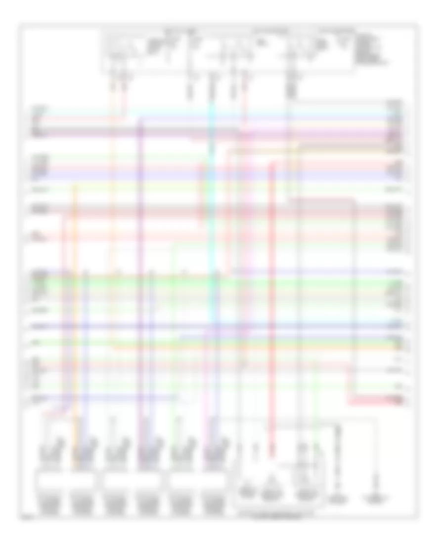
3.5L, Engine Performance Wiring Diagram (1 of 4) for Infiniti M35 2008

List of elements for 3.5L, Engine Performance Wiring Diagram (1 of 4) for Infiniti M35 2008:
- (behind center console) unified meter & a/c amplifier
- (right end of dash)
- A/f-ip1
- A/t assembly
- Af-h1
- Af-h2
- Af-un1
- Af-vm1
- Af-vm2
- At-p
- Avcc
- Avcc2
- C-ivc (l)
- C-ivc (r)
- Can high
- Can low
- Computer data lines system
- Condenser (top right of engine compt)
- Crankshaft position sensor (pos) (left front of engine)
- Ecm
- Engine control module (behind right side of dash)
- Evap
- Evap canister purge volume control solenoid valve (top right rear of engine)
- F108
- F44 (top front of engine)
- Fpcm
- Fpcmck
- Ftrps
- Fuel injectors (inj 1, 3 & 5: top right of engine) (inj 2, 4 & 6: top left of engine)
- Gnd
- Grd
- Inj#1
- Inj#2
- Inj#3
- Inj#4
- Inj#5
- Inj#6
- Knk1
- Knock sensor (top rear of engine)
- M70
- M70 (right end of dash)
- Motor1
- Motor2
- Nca
- O2hrl
- O2hrr
- O2srl
- Phase lh
- Phase rh
- Pnk
- Pos
- Ps pres
- Qa+
- Red
- Refrigerant pressure sensor (right front of engine compt)
- Starting/ charging system
- Tcm (transmission control module)
- Tps1
- Vmot
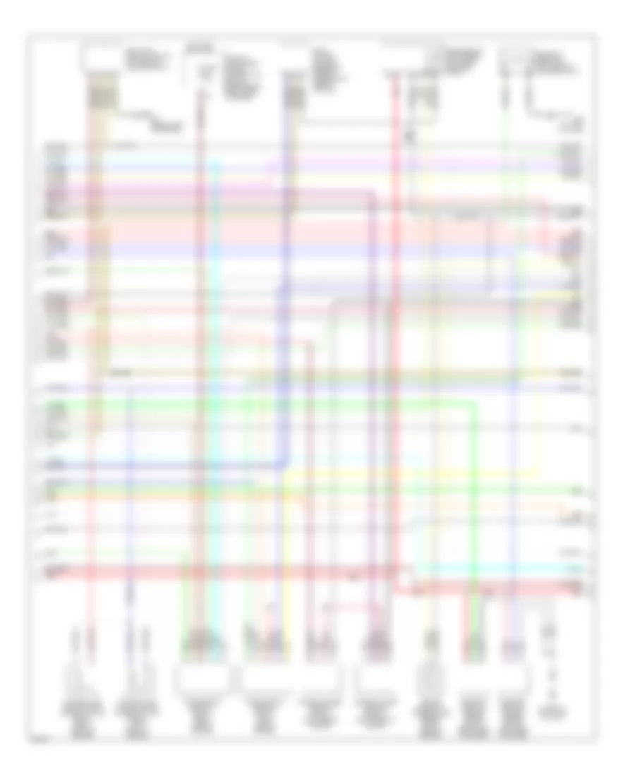
3.5L, Engine Performance Wiring Diagram (2 of 4) for Infiniti M35 2008
List of elements for 3.5L, Engine Performance Wiring Diagram (2 of 4) for Infiniti M35 2008:
- Ecm relay
- Electric throttle control actuator (top left rear of engine)
- F22 (top front of engine)
- F31
- Fuel pump relay
- Fuse 15a
- Fuse 20a
- Hot at all times
- Hot in on or start
- Ignition coil 1 (w/ power transistor) (top right of engine)
- Ignition coil 2 (w/ power transistor) (top left of engine)
- Ignition coil 3 (w/ power transistor) (top right of engine)
- Ignition coil 4 (w/ power transistor) (top left of engine)
- Ignition coil 5 (w/ power transistor) (top right of engine)
- Ignition coil 6 (w/ power transistor) (top left of engine)
- Ipdm e/r (intelligent power distribution module engine room) (right rear of engine compt)
- M70 (right end of dash)
- Nca
- Plug spark
- Red
- Spark plug
- Throttle control motor
- Throttle control motor relay
- Throttle position (tp) sensor 1
- Throttle position (tp) sensor 2
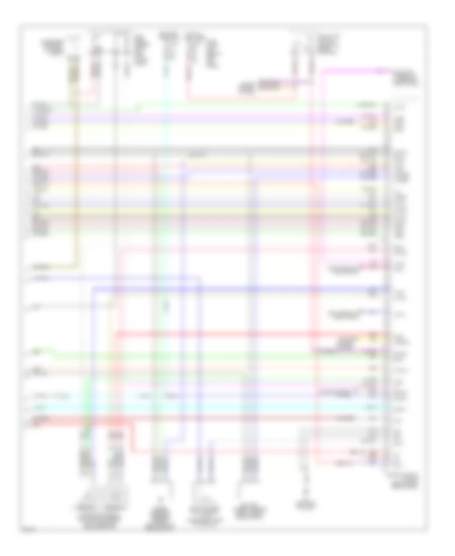
3.5L, Engine Performance Wiring Diagram (3 of 4) for Infiniti M35 2008
List of elements for 3.5L, Engine Performance Wiring Diagram (3 of 4) for Infiniti M35 2008:
- Air fuel ratio sensor 1 (bank 1) (right side of engine)
- Air fuel ratio sensor 1 (bank 2) (left side of engine)
- B40 (at left "c" pillar)
- B5 (behind left kick panel)
- Camshaft position sensor (phase) (bank 1) (right rear of engine)
- Camshaft position sensor (phase) (bank 2) (left rear of engine)
- Dropping resistor (left side of luggage compt)
- Engine coolant temperature sensor (right rear of engine)
- Evap control system pressure sensor (under right rear of vehicle)
- Fuel pump control module (left side of luggage compt)
- Fuse 15a
- Heated oxygen sensor 2 (bank 1) (left side of engine)
- Heated oxygen sensor 2 (bank 2) (left front of engine)
- Hot in on or start
- Intake valve timing control solenoid valve (bank 1) (right front of engine)
- Intake valve timing control solenoid valve (bank 2) (left front of engine)
- Ipdm e/r (intelligent power distribution module engine room) (right rear of engine
- M70 (right end of dash)
- Mass airflow (maf) sensor (left front of engine compt)
- Red
3.5L, Engine Performance Wiring Diagram (4 of 4) for Infiniti M35 2008
List of elements for 3.5L, Engine Performance Wiring Diagram (4 of 4) for Infiniti M35 2008:
- 15a
- A/f-ia1
- A/f-ia2
- Accelerator pedal position (app) sensor (on accelerator pedal bracket)
- Af-ip2
- Af-un2
- Aps1
- Aps2
- Ascdsw
- Avcc
- Avcc2
- Batt
- Battery current sensor (right side of engine compt)
- Bncsw
- Brake
- Can l
- Can-h
- Cdcv
- Computer data lines system
- Condenser (top right of engine compt)
- Cruise control system
- Cursen
- Data link connector (lower left side of dash)
- E101
- Engine control module (behind right side of dash)
- Evap canister vent control valve (under right rear of vehicle)
- F108
- Fpr
- Fuel level sensor unit & fuel pump (in fuel tank)
- Fuse 10a
- Fuse 15a
- Fuse block (j/b) (behind left kick panel)
- Gnd
- Gnd a
- Gnd-02
- Gnd-a
- Gnd-a2
- Hot at all times
- Hot in on or start
- Ign sw
- Ign#1
- Ign#2
- Ign#3
- Ign#4
- Ign#5
- Ign#6
- Kline
- M70 (right end of dash)
- M71
- Motrly
- Neut
- O2srr
- Pdpres
- Pnk
- Power steering pressure sensor (left front of engine compt)
- Red
- Sensor 1
- Sensor 2
- Ssoff
- Stop lamp switch (on brake pedal bracket)
- Tps2