ENGINE PERFORMANCE
5.6L
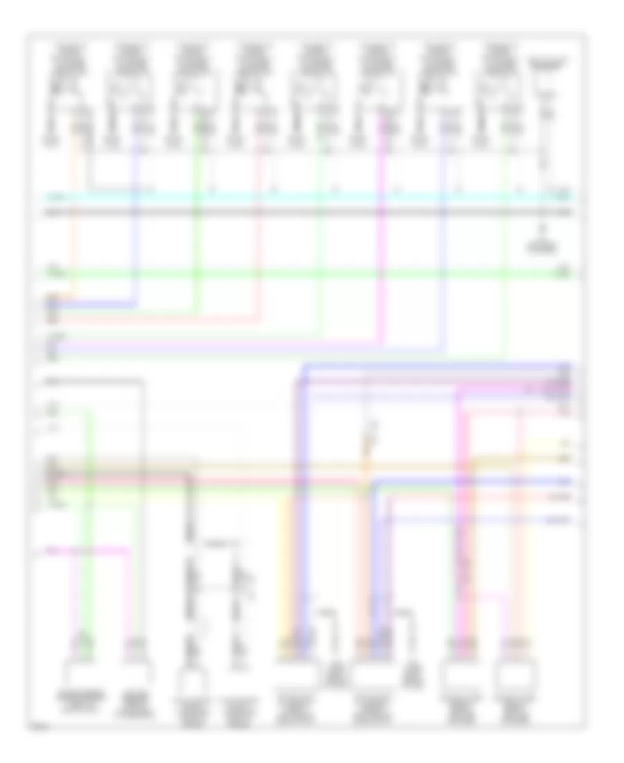
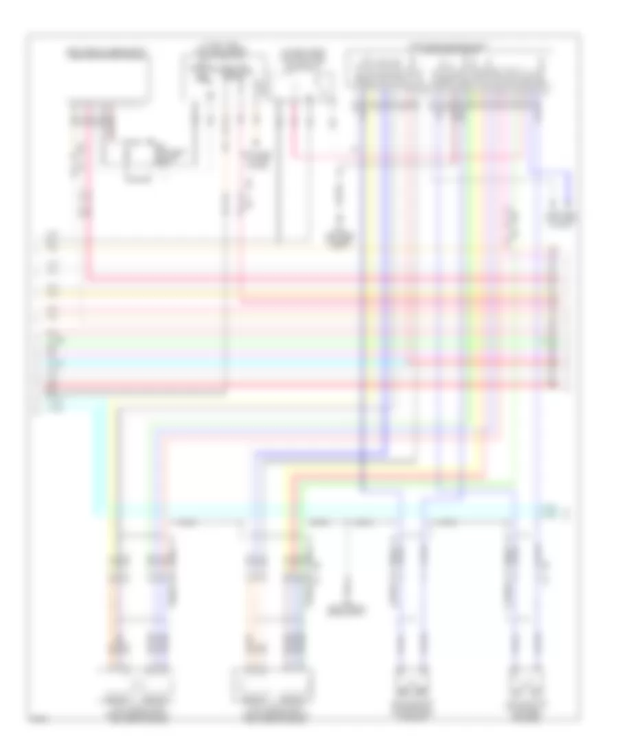
5.6L, Engine Performance Wiring Diagram (1 of 7) for Infiniti M56 2013

List of elements for 5.6L, Engine Performance Wiring Diagram (1 of 7) for Infiniti M56 2013:
- (inj 3 & 5: top left of engine) (inj 2 & 8: top right of engine) fuel injectors
- (left air intake tube) mass air flow sensor (bank 1)
- (left side of dash) m11
- (lower right center of dash) m55
- (right air intake tube) mass air flow sensor (bank 2)
- A/t assembly
- Can-h
- Can-l
- Computer data lines system
- E20
- Ecm (engine control module) (right rear of engine compt)
- Ecm gnd
- Eng colnt temp sens
- Eng oil pres sens
- Eng oil temp sens
- Engine coolant temperature sensor (right rear of engine)
- Engine oil pressure sensor (lower front left side of engine)
- Engine oil temperature sensor (lower front left side of engine)
- Exhaust (bank 1)
- Exhaust (bank 2)
- Exhaust valve timing control solenoid valve (bank 1) (left front of engine)
- Exhaust valve timing control solenoid valve (bank 2) (right front of engine)
- F103 m116
- F110
- F130
- F139
- F40
- F60
- F69
- Fuel inj 2 (hi)
- Fuel inj 2 (lo)
- Fuel inj 3 (hi)
- Fuel inj 3 (lo)
- Fuel inj 5 (hi)
- Fuel inj 5 (lo)
- Fuel inj 8 (hi)
- Fuel inj 8 (lo)
- Fuel inj dr pwr sply
- Fuel rail pres sens
- Fuel rail pressure sensor (top right rear of engine)
- Ign sig 1
- Ign sig 2
- Ign sig 3
- Ign sig 4
- Ign sig 5
- Ign sig 6
- Ign sig 7
- Ign sig 8
- Intake (bank 1)
- Intake (bank 2)
- Intake air temperature sensor
- Intake valve timing control solenoid valve (bank 1) (left front of engine)
- Intake valve timing control solenoid valve (bank 2) (right front of engine compt)
- Joint connector
- Knock sens (bank 1)
- Knock sens (bank 2)
- Lo fuel pres sens mass air flow sens (bank 2)
- Nca
- Pnk
- Pwr strng pres sens
- Red
- Sens 1 (bank 1)
- Sens 1 (bank 2)
- Sens 2 (bank 1)
- Sens 2 (bank 2)
- Sens gnd
- Sens pwr sup
- Shield
- Start rly
- Tcm (transmission control module)
- Temp sens (bank 1) mass air flow sens (bank 1)
- Trans range sw
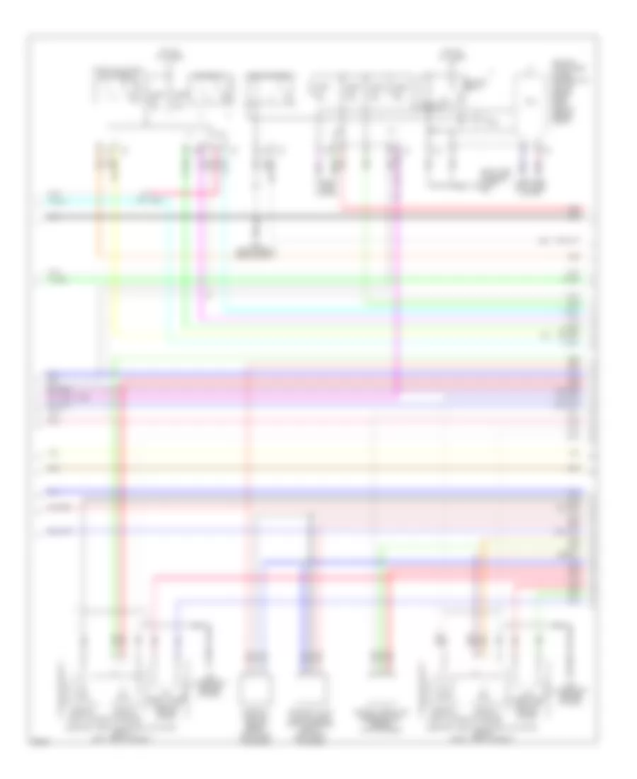
5.6L, Engine Performance Wiring Diagram (2 of 7) for Infiniti M56 2013
List of elements for 5.6L, Engine Performance Wiring Diagram (2 of 7) for Infiniti M56 2013:
- (left "c" pillar) condenser
- (top left of engine) ignition coil 1 (w/ power transistor)
- (top left of engine) ignition coil 3 (w/ power transistor)
- (top left of engine) ignition coil 5 (w/ power transistor)
- (top left of engine) ignition coil 7 (w/ power transistor)
- (top right of engine) ignition coil 2 (w/ power transistor)
- (top right of engine) ignition coil 4 (w/ power transistor)
- (top right of engine) ignition coil 6 (w/ power transistor)
- (top right of engine) ignition coil 8 (w/ power transistor)
- Air fuel ratio (a/f) sensor 1 (bank 1) (left rear of engine compt)
- Air fuel ratio (a/f) sensor 1 (bank 2) (right rear of engine compt)
- E20
- F211
- F34 (left front of engine)
- F40
- F68
- Heated oxygen sensor 2 (bank 1) (left side of engine)
- Heated oxygen sensor 2 (bank 2) (left side of engine)
- Knock sensor (bank 1) (top center front of engine)
- Knock sensor (bank 2) (top center front of engine)
- Low fuel pressure sensor (top of right cylinder bank)
- M55 (lower right center of dash)
- Nca
- Pnk
- Power steering pressure sensor (front of engine compt)
- Red
- Shield
- Spark plug
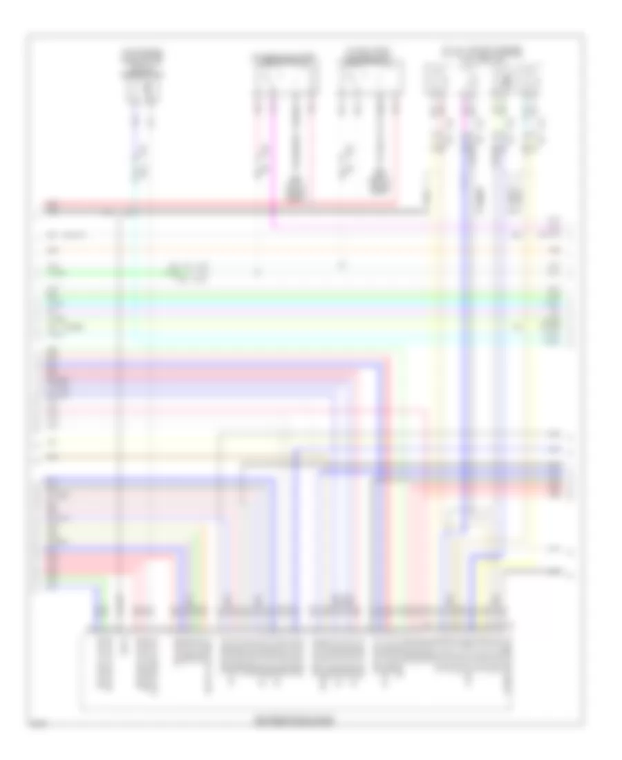
5.6L, Engine Performance Wiring Diagram (3 of 7) for Infiniti M56 2013
List of elements for 5.6L, Engine Performance Wiring Diagram (3 of 7) for Infiniti M56 2013:
- (or red)
- (right side of engine compt) e46
- Camshaft position sensor (bank 1) (left front of engine)
- Close open
- Computer data lines system
- Cooling fans system
- Cpu
- E20
- E46 (right side of engine compt)
- Ecm relay
- Electric throttle control actuator (bank 1) (left throttle body)
- Electric throttle control actuator (bank 2) (right throttle body)
- Exhaust valve timing control position sensor (bank 1) (left front of engine)
- F40
- Fuel pump relay
- Fuse 10a
- Fuse 15a
- Hot at all times
- Ignition relay
- Ipdm e/r (intelligent power distribution module engine room) (right rear of engine compt)
- M55 (lower right center of dash)
- Manifold absolute pressure (map) sensor (top of engine)
- Nca
- Open close
- Pnk
- Red
- Sensor 1
- Sensor 2
- Throttle control motor
- Throttle control motor relay
- Throttle position sensor
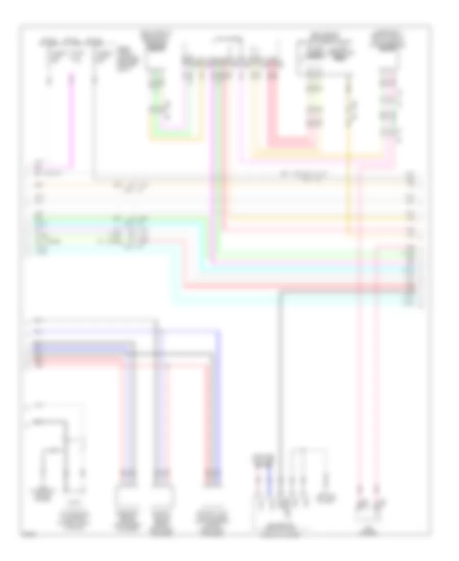
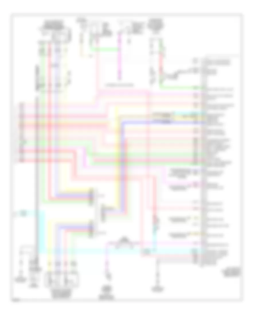
5.6L, Engine Performance Wiring Diagram (4 of 7) for Infiniti M56 2013
List of elements for 5.6L, Engine Performance Wiring Diagram (4 of 7) for Infiniti M56 2013:
- (in fuse, fusible link & relay box) injector relay 1
- (in fusible link holder) injector relay 2
- (inj 1 & 7: top left of engine) (inj 4 & 6: top right of engine) fuel injectors
- (or red)
- (top of engine) evap canister purge volume control solenoid valve
- A/f sens 1 (bank 1)
- A/f sens 1 (bank 2)
- A/f sens 1(bank 2)
- Crnkshft pos sens
- E106
- E22 (left rear of engine compt)
- E46 (right side of engine compt)
- Ecm (engine control module) (right rear of engine compt)
- Evap solenoid valve
- F103
- F111
- F130
- F139
- F60
- F69
- Fuel inj 1 (hi)
- Fuel inj 1 (lo)
- Fuel inj 4 (hi)
- Fuel inj 4 (lo)
- Fuel inj 6 (hi)
- Fuel inj 6 (lo)
- Fuel inj 7 (hi)
- Fuel inj 7 (lo)
- Hi pres fuel pump
- Hi pres fuel pump lo
- M116
- Mtr (bank 1) (close)
- Mtr (bank 1) (open)
- Mtr (bank 2) (close)
- Mtr (bank 2) (open)
- Nca
- Pnk
- Pres sens
- Red
- Sens (bank 1)
- Sens (bank 2)
- Sens 1 (bank 1)
- Sens 2 (bank 1)
- Sens 2 (bank 2)
- Sens gnd
- Sens pwr sup
- Shield
- Throttle pos sens 2
5.6L, Engine Performance Wiring Diagram (5 of 7) for Infiniti M56 2013
List of elements for 5.6L, Engine Performance Wiring Diagram (5 of 7) for Infiniti M56 2013:
- (or red)
- (right front of engine compt) refrigerant pressure sensor
- (right rear of engine compt) battery current sensor
- (under right rear of vehicle) evap control system pressure sensor
- B71
- B72
- Battery current sensor
- Battery temperature sensor
- Camshaft position sensor (bank 2) (right front of engine)
- Can-h
- Can-l
- Combination meter
- Computer data lines system
- Crankshaft position sensor (bottom rear of engine)
- E105
- E106
- Exhaust valve timing control position sensor (bank 2) (right front of engine)
- Fuse & fusible link block (right rear of engine compt)
- Fuse 15a
- Fusible link g 50a
- Fusible link i 30a
- Gnd
- High pressure fuel pump (top right front of engine)
- Hot at all times
- M11 (left side of dash)
- M23
- M28
- M29
- M30
- M55 (lower right center of dash)
- Malfunction indicator lamp
- Nca
- Pcb harness
- Pnk
- Red
- Sens gnd level fuel
- Tan
5.6L, Engine Performance Wiring Diagram (6 of 7) for Infiniti M56 2013
List of elements for 5.6L, Engine Performance Wiring Diagram (6 of 7) for Infiniti M56 2013:
- (in fuel tank) fuel level sensor unit & fuel pump
- (in fuse, fusible link & relay box) vvel actuator motor relay
- (right rear of engine compt) vvel control module
- (right side of luggage compt) fuel pump control module
- Abort
- Agnd2
- Agnd4
- Avcc1
- Avcc2
- Avcc3
- Avcc4
- B201
- B224 (right rear quarter panel)
- B230
- B51
- Can h
- Can l
- Cluster system
- Computer data lines system
- E106
- E20
- E22 (left rear of engine compt)
- E46 (right side of engine compt)
- F40
- Fuel tank temperature sensor
- High lift
- Instrument
- Low lift
- Low pressure fuel pump
- M-rly
- M117
- Motor-b 1
- Motor1-b2
- Motor2-b1
- Motor2-b2
- Nca
- P-gnd
- Pnk
- Red
- Sens gnd
- Sensor 1
- Sensor 2
- Shield
- Tan
- V pwr sply
- Vel/s1-b1
- Vel/s1-b2
- Vel/s2-b1
- Vel/s2-b2
- Vmot-b1
- Vmot-b2
- Vvel actuator motor (bank 1) (left rear of engine)
- Vvel actuator motor (bank 2) (top right rear of engine)
- Vvel control shaft position sensor (bank 1) (left rear of engine)
- Vvel control shaft position sensor (bank 2) (right rear of engine)
5.6L, Engine Performance Wiring Diagram (7 of 7) for Infiniti M56 2013
List of elements for 5.6L, Engine Performance Wiring Diagram (7 of 7) for Infiniti M56 2013:
- (on accelerator pedal bracket) accelerator pedal position sensor
- (under rear of vehicle) evap canister vent control valve
- Acc pedal sens 2
- Accelerator pedal position sensor (on accelerator pedal bracket)
- Accelerator sens 1
- Ascd br sw
- Ascd strng sw
- B71
- B72
- Batt current sens
- Batt temp sens
- Can comm line
- Computer data lines system
- Cruise control system
- E103
- E106
- E115
- Ecm (back-up)
- Ecm (engine control module) (right rear of engine compt)
- Ecm (self shut-off)
- Ecm comm line
- Ecm gnd
- Engine spd sig out
- Evap vent ctrl valve
- Exterior lights system
- Fpcm check
- Fuel inj dr pwr sply
- Fuel pump ctrl module
- Fuel tank pres sens
- Fuel temp sens
- Fuse 10a
- Fuse block (j/b) (behind left end of dash)
- Hot at all times
- Ign sw
- M150
- M151
- M160
- M29
- M30
- M95 (right side of dash)
- Mtr pwr sply
- Mtr rly
- Pcb harness
- Pnk
- Power steering control unit (behind right side of dash)
- Pwr sply for ecm
- Red
- Refr pres sens
- Sens gnd
- Sens pwr sply
- Sensor 1
- Sensor 2
- Shield
- Sig (vvel ctrl module)
- Stop lamp sw
- Stop lamp switch (on brake pedal bracket)
- Tacho eng
- Tan
- W/ icc
- W/o icc