ENGINE PERFORMANCE
4.1L
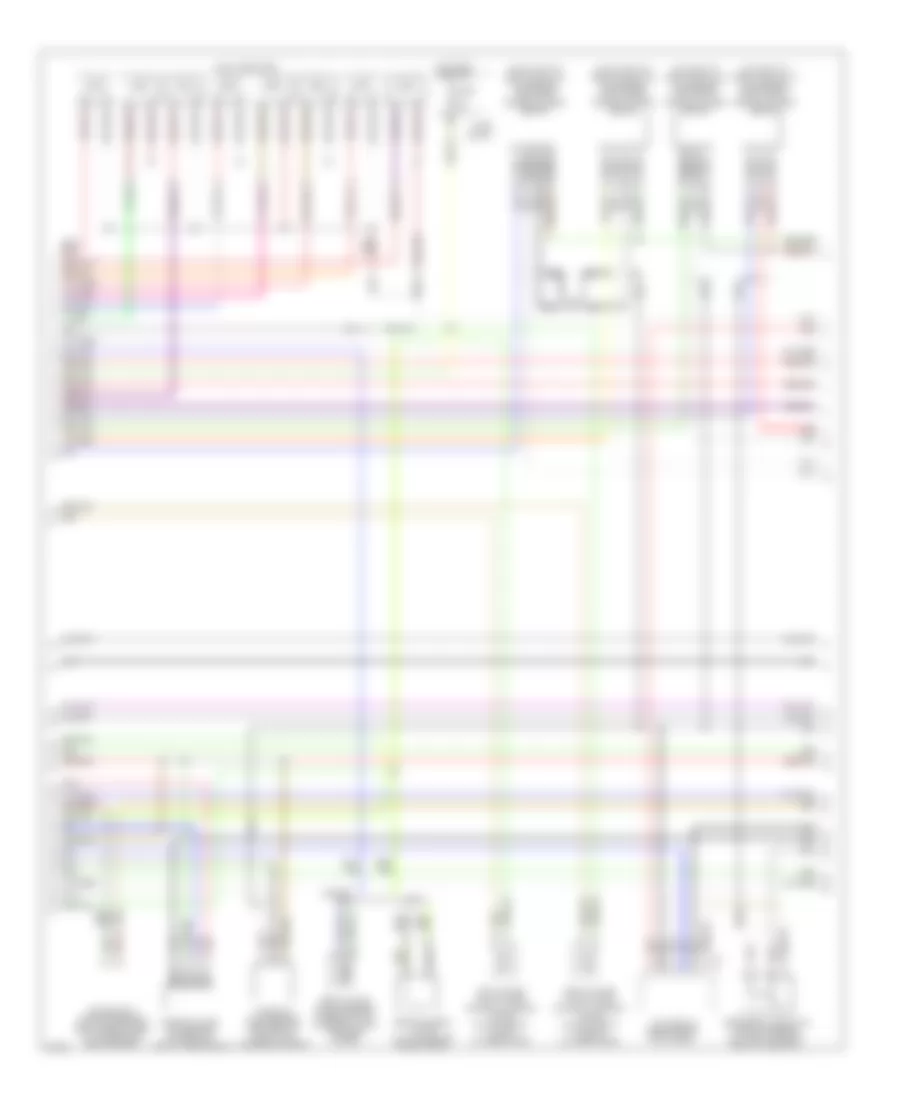
4.1L, Engine Performance Wiring Diagrams (1 of 4) for Infiniti Q45 1998

List of elements for 4.1L, Engine Performance Wiring Diagrams (1 of 4) for Infiniti Q45 1998:
- (30-33 not used)
- (37-40 not used)
- (cali)
- (front of right front fender)
- (on left front side of eng, forward of left throttle body) iacv-aac valve
- Air conditioning system
- Check connector (in right rear of eng compt)
- Cooling fans system
- Eccs control module (ecm) (behind right kick panel)
- Evap canister purge control solenoid valve (cali only) (on top right rear of eng)
- Evap canister purge volume control solenoid valve (cali only) (on top right rear of eng)
- Evap canister vent control valve (cali only) (under right rear of vehicle, on evap canister)
- G101
- Iacv-ficd solenoid valve (left front side of eng compt, forward of throttle body)
- Ignition coils
- Instrument cluster system
- Map/baro switch solenoid valve (cali only) (on top center rear of eng)
- Pnk
- Power steering oil pressure switch (on power steering high pressure tube)
- Red
- Resistor (behind right kick panel)
- Vacuum cut valve bypass valve (cali only) (under right rear of vehicle, forward of evap canister)
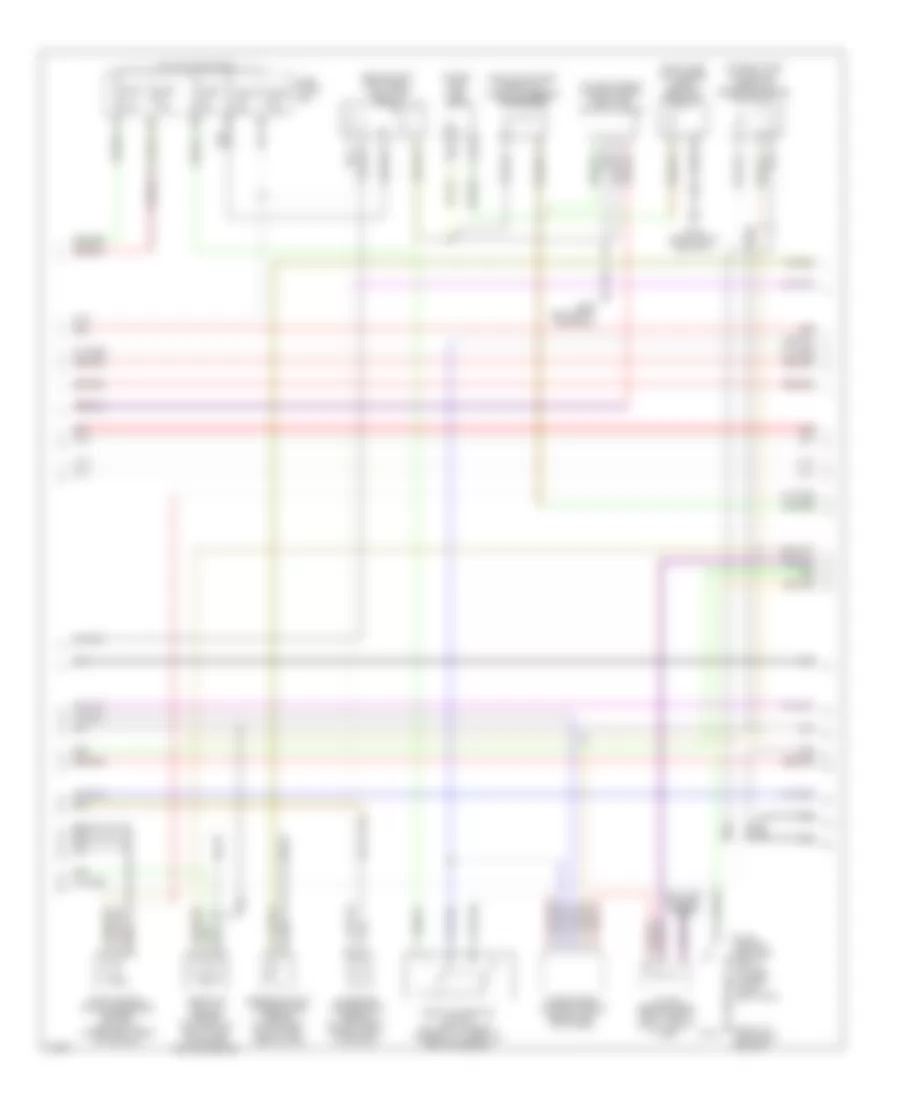
4.1L, Engine Performance Wiring Diagrams (2 of 4) for Infiniti Q45 1998
List of elements for 4.1L, Engine Performance Wiring Diagrams (2 of 4) for Infiniti Q45 1998:
- tac module (behind right kick panel)
- (on inlet of left catalytic converter) left front heated oxygen sensor
- (on inlet of right catalytic converter) right front heated oxygen sensor
- (on outlet of left catalytic converter) left rear heated oxygen sensor
- (on outlet of right catalytic converter) right rear heated oxygen sensor
- Cali
- Camshaft posi- tion sensor (on front of left cylinder head)
- Crankshaft position sensor (bottom right side of transmission bellhousing)
- Egr valve & evap canister purge control solenoid valve (top rear of eng)
- Egrc-solenoid valve (on top center rear of eng)
- Except cali
- F75
- Fuel injectors
- Fuse 10a
- Fuse block
- Hot in on or start
- Left intake valve timing control solenoid valve (on top front of left cylinder head)
- Mass air flow sensor (between air duct & air cleaner housing)
- Nca
- Pnk
- Red
- Right intake valve timing control solenoid valve (on top front of right cylinder head)
- Secondary throttle position sensor (on throttle body, next to air duct)
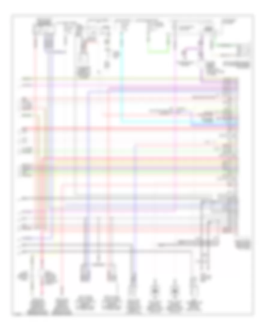
4.1L, Engine Performance Wiring Diagrams (3 of 4) for Infiniti Q45 1998
List of elements for 4.1L, Engine Performance Wiring Diagrams (3 of 4) for Infiniti Q45 1998:
- (above left rear wheelwell, taped to harness) condenser
- (behind right kick panel) fuel pump relay
- (front of left front fender)
- (in fuel tank) fuel pump
- (on left side of luggage compt) fuel pump control module
- (on right side of firewall) absolute pressure sensor (cali only)
- (right side of luggage compt) dropping resistor
- 12g
- 13h
- Anti-lock brakes system
- Engine coolant temperature sensor (on top right fonr of eng, near inj no2)
- Evap control system pressure sensor (cali only) (under right rear of vehicle)
- Fuse 10a
- Fuse 15a
- Fuse 7.5a
- Fuse block (j/b)
- G100
- G309 (left front door sill)
- G316 (right front door sill)
- Hot in on or start
- Intake air temperature sensor (on left front of eng compt, in air duct)
- J/c no6 (behind upper right side of dash, tape to harn)
- Nca
- Park/ neutral position relay (in fuse, fusible link & relay box)
- Red
- Throttle position sensor (on throttle body, near intake mani- fold collector)
- Throttle position switch (on throttle body, integral to throttle position sensor)
- Transmission control module (behind left kick panel)
4.1L, Engine Performance Wiring Diagrams (4 of 4) for Infiniti Q45 1998
List of elements for 4.1L, Engine Performance Wiring Diagrams (4 of 4) for Infiniti Q45 1998:
- (102-104 not used)
- (109-120 not used)
- (84-88 not used)
- (94-95 not used)
- (behind right kick panel) eccs relay
- (cali)
- Acc
- Air conditioning system
- Condenser (taped to harness, on right side of eng)
- Cooling fans system
- Data link connector (for consult) (under left side of dash, beside hood lock release handle)
- Data link connector (for gst) (under left side of dash, near hood lock release handle)
- Defogger system
- Eccs control module (ecm) (behind right kick panel)
- Egr temperature sensor (top left rear of eng)
- Fuel tank gauge unit (tank fuel temperature sensor) (in fuel tank)
- Fuse 7.5a
- Fuse block
- Fuse block (j/b)
- Fuse, fusible link & relay box
- G110 (top left front of eng)
- Headlights system
- Hot at all times
- Hot in on or start
- Hot in start
- Ignition switch
- Instrument cluster
- J/c 2 (behind left side of dash, near fuse block)
- J/c 8 (behind left kick panel)
- J/c no6 (behind upper right side of dash, taped to harn)
- Left intake valve timing control position sensor (on rear of left cylinder head)
- Left knock sensor (below left side of intake manifold)
- Malfunction ind lamp
- Nca
- Off
- Pnk
- Red
- Right intake valve timing control position sensor (on rear of right cylinder head)
- Right knock sensor (below right side of intake manifold)
- Speedo- meter
- Start
- Transmissions system
- Vehicle speed sensor (on transmission rear extension)