ENGINE PERFORMANCE
4.5L
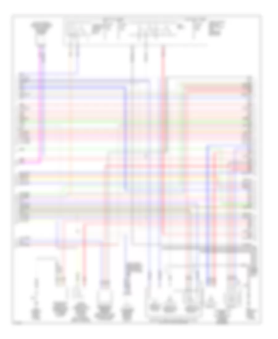
4.5L, Engine Performance Wiring Diagram (1 of 5) for Infiniti Q45 2005

List of elements for 4.5L, Engine Performance Wiring Diagram (1 of 5) for Infiniti Q45 2005:
- (on right front fenderwell)
- Avcc
- Avcc2
- C-ivc (l)
- C-ivc (r)
- Cooling fans system
- E24 (on right front strut tower)
- E42
- Engine control module (behind glove box)
- Evap
- F8 (at left front of eng compt)
- Fpcm
- Fpcmck
- Ftrps
- Fuel injector
- Fuse 10a
- Fuse 15a
- Fuse block (j/b) 1 (behind left end of dash)
- Fuse block (j/b) 2 (behind right kick panel)
- Gnd
- Hot at all times
- Hot in on or start
- Ign 7
- Ignition coil 1 (w/ power transistor)
- Ignition coil 2 (w/ power transistor)
- Ignition coil 3 (w/ power transistor)
- Ignition coil 4 (w/ power transistor)
- Ignition coil 5 (w/ power transistor)
- Ignition coil 6 (w/ power transistor)
- Ignition coil 7 (w/ power transistor)
- Ignition coil 8 (w/ power transistor)
- Inj 1
- Inj 2
- Inj 3
- Inj 4
- Inj 5
- Inj 6
- Inj 7
- Ivc pus (r)
- Knk1
- Knk2
- Knock sensor (bank 1) (below left side of intake manifold)
- Knock sensor (bank 2) (below right side of intake manifold)
- Motor1
- Motor2
- Nca
- Nca nca
- O2hfl
- O2hfr
- O2hrl
- O2hrr
- O2sfl
- O2sfr
- O2srl
- Pdpres
- Phase
- Plug spark
- Pnk
- Pos
- Ps pres
- Qa+
- Red
- Rfrm
- Spark plug
- Tps1
- V mot
- Vias
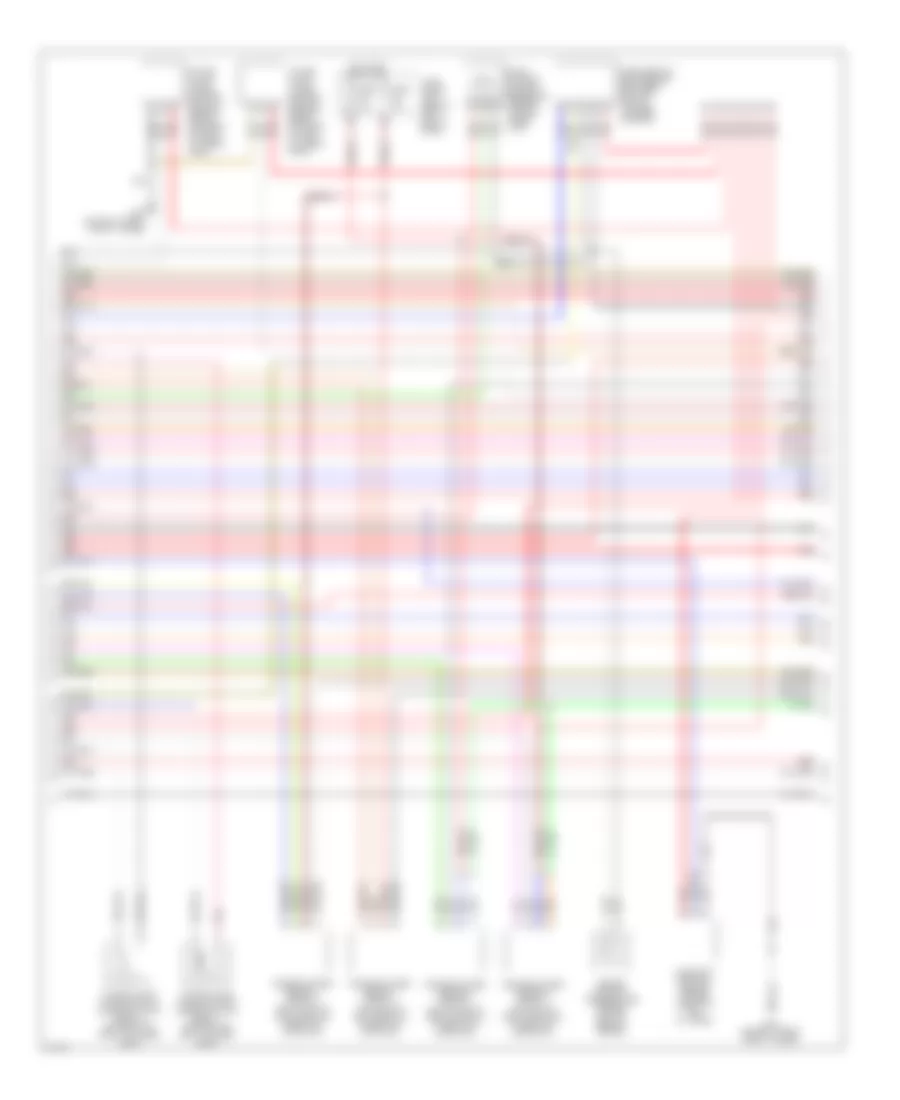
4.5L, Engine Performance Wiring Diagram (2 of 5) for Infiniti Q45 2005
List of elements for 4.5L, Engine Performance Wiring Diagram (2 of 5) for Infiniti Q45 2005:
- (left front engine compt, near eng oil level gauge) f8
- (on top front center of engine) vias control solenoid valve
- Accelerator pedal position (app) sensor (on pedal bracket)
- Condenser (center rear of engine compt)
- Crankshaft position sensor (pos) (on rear of cylinder block)
- E213
- E24 (on right front strut tower)
- Ecm relay
- Electric throttle control actuator (on left side of engine)
- Evap canister purge volume control solenoid valve (on top right rear of engine)
- F19
- Fuse 15a
- Fuse 20a
- Fuse, fusible link and relay block (j/b) (in engine room box)
- Hot at all times
- Nca
- Pnk
- Red
- Refrigerant pressure sensor (right front of eng compt, near condenser)
- Sensor 1
- Sensor 2
- Throttle control motor
- Throttle control motor relay
- Throttle position (tp) sensor 1
- Throttle position (tp) sensor 2
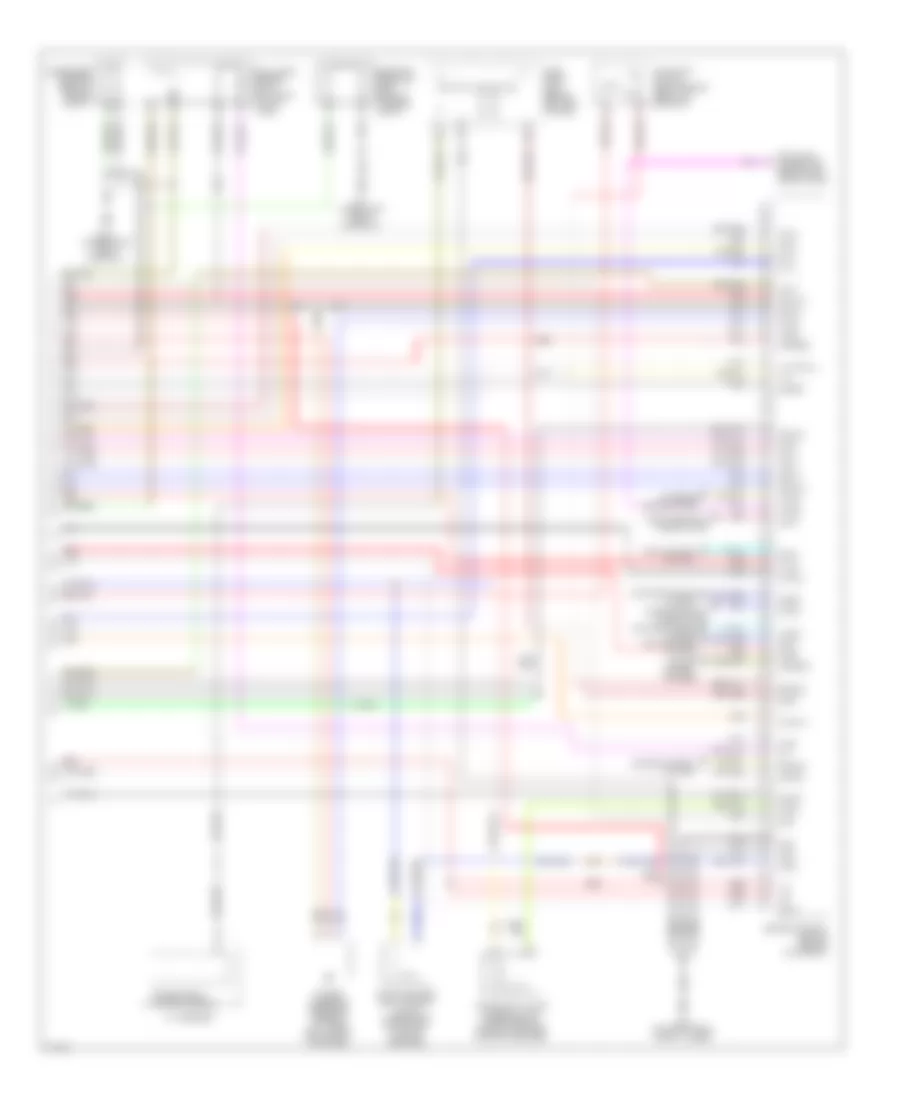
4.5L, Engine Performance Wiring Diagram (3 of 5) for Infiniti Q45 2005
List of elements for 4.5L, Engine Performance Wiring Diagram (3 of 5) for Infiniti Q45 2005:
- Camshaft position sensor (phase) (front of left cyl head)
- E24 (on right front strut tower)
- Engine coolant temperature sensor (on top rear of engine)
- Evap control system pressure sensor (in evap purge line)
- Fuse 10a
- Fuse block (j/b) 1 (behind left end of dash)
- Heated oxygen sensor 1 (bank 1) (on inlet of left manifold three way catalyst)
- Heated oxygen sensor 1 (bank 2) (on outlet of left manifold three way catalyst)
- Heated oxygen sensor 2 (bank 1) (on inlet of right manifold three way catalyst)
- Heated oxygen sensor 2 (bank 2) (on outlet of right manifold three way catalyst)
- Hot in on or start
- Intake valve timing control position sensor (bank 1) (on front of left cylinder head)
- Intake valve timing control position sensor (bank 2) (on front of right cylinder head)
- Intake valve timing control solenoid valve (bank 1) (on front of left cylinder head)
- Intake valve timing control solenoid valve (bank 2) (on front of right cylinder head)
- M24 (on right front strut tower)
- Mass airflow (maf) sensor (between air duct and air cleaner housing)
- Pnk
- Red
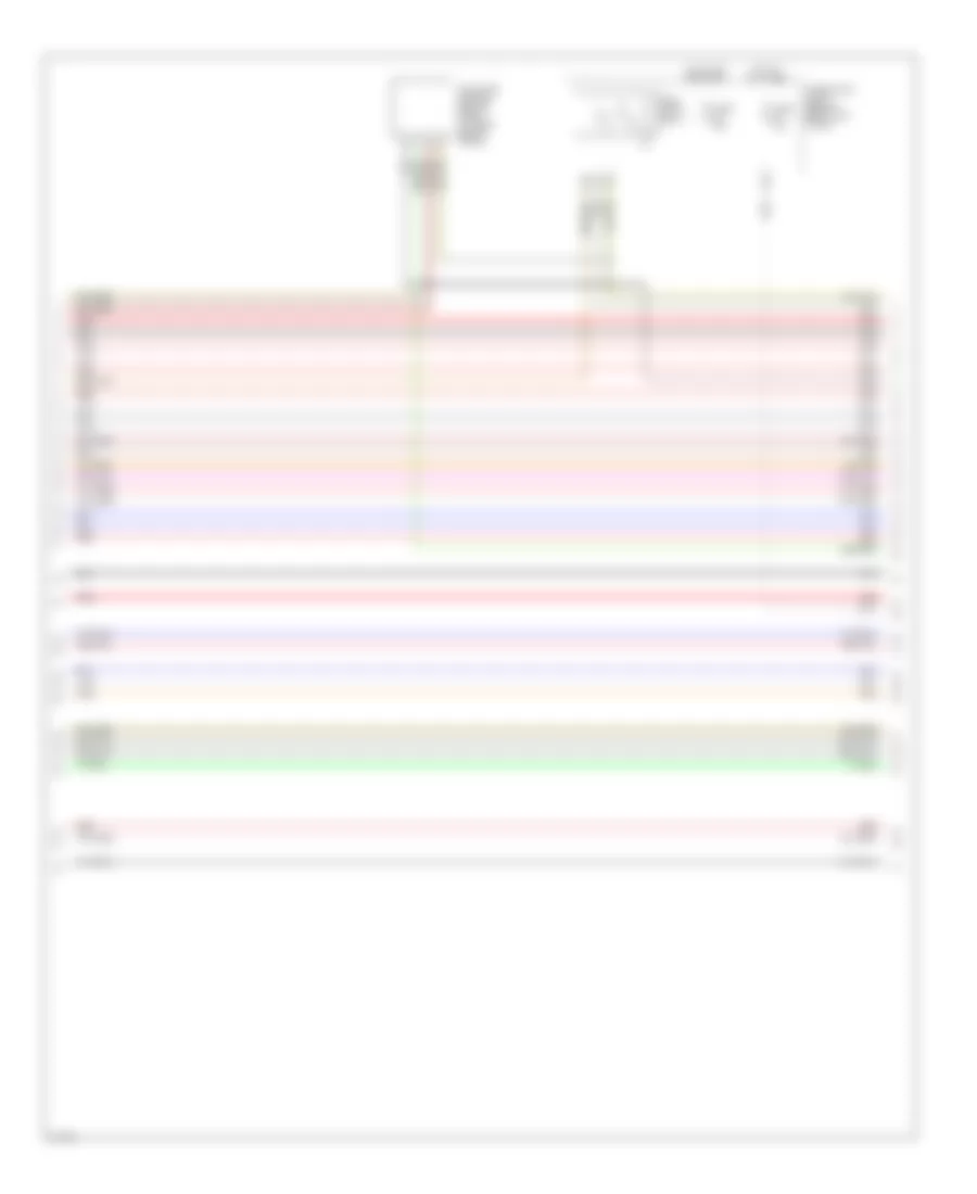
4.5L, Engine Performance Wiring Diagram (4 of 5) for Infiniti Q45 2005
List of elements for 4.5L, Engine Performance Wiring Diagram (4 of 5) for Infiniti Q45 2005:
- Fuel pump control module (fpcm) (at right side of trunk)
- Fuel pump relay
- Fuse 10a
- Fuse 15a
- Fuse block (j/b) 2 (behind right kick panel)
- Hot at all times
- Hot in on or start
- Red
4.5L, Engine Performance Wiring Diagram (5 of 5) for Infiniti Q45 2005
List of elements for 4.5L, Engine Performance Wiring Diagram (5 of 5) for Infiniti Q45 2005:
- 17d
- 19d
- A/t assembly
- Air conditioning system
- Air conditioning system cooling fans system
- Aps1
- Aps2
- Ascdsw
- Avcc
- Avcc2
- B17 (under left front door sill)
- B217 (under right front door sill)
- Batt
- Bncsw
- Brake
- Can l
- Can-h
- Cdcv
- Computer data lines system
- Condenser (center rear of engine compt)
- Cooling fans system
- Cruise control system
- Cvbv
- Data link connector (below left side of dash)
- Dropping resistor (left rear of luggage compt)
- E24 (on right front strut tower)
- Engine control module (behind glove box)
- Evap canister vent control valve (under rear of vehicle, on evap canister)
- Exterior lights system
- Fpr
- Fuel level sensor unit & fuel pump (in fuel tank)
- Fuse block (j/b) 1 (behind left end of dash)
- Gnd
- Gnd 02
- Gnd a
- Gnd a2
- H/lmp
- Ign 1
- Ign 2
- Ign 3
- Ign 4
- Ign 5
- Ign 6
- Ign 8
- Ign sw
- Inj 8
- Ivc pus (l)
- Kline
- Loadl
- Moyrly
- Neut
- O2srr
- Pdpres
- Pnk
- Power steering pressure sensor (at lower right front of engine)
- R/def
- Red
- Rfrh
- Rfrl
- Ssoff
- Stoplight switch (above brake pedal, on bracket)
- Tps2
- Transmission control module
- Vacuum cut valve bypass valve (under rear of vehicle, forward of evap canister)