ENGINE PERFORMANCE
2.8L
2.8L, Engine Performance Wiring Diagram (1 of 5) for Isuzu i-280 S 2006

List of elements for 2.8L, Engine Performance Wiring Diagram (1 of 5) for Isuzu i-280 S 2006:
- (m/t)
- (on floor, under driver's seat) (4wd) transfer case shift control module
- 4wd lo sw
- A/c comp rly
- A/c press
- A/c refrigerant pressure sensor (right rear of engine compt)
- Accelerator pedal position (app) sensor (on accelerator bracket)
- Accy voltage
- Air conditioning system
- App 1
- App 1 +5v ref
- App 1 low ref
- App 2
- App 2 +5v ref
- App 2 low ref
- App sens 1
- App sens 2
- Arp +5v ref
- Arp low ref
- Battery b+
- Can vent fuse 69 10a
- Class 2 data
- Cluster fuse 38 10a
- Computer data lines system
- Cpp sw sig
- Cruise control system
- Cruise ctrls
- Diag enable
- E11
- Evap vent sol
- Evaporative emission (evap) canister vent solenoid (front of fuel tank)
- Exterior lights system
- Ftp +5v ref
- Fuel lvl sens
- Fuel pump rly
- Fuel tank press
- Fuel tank pressure (ftp) sensor (at top left rear of fuel tank)
- Hot at all times
- Hot in run & start
- Ignition 1
- Instrument panel cluster
- Low ref
- Malfunction indicator lamp (mil)
- Mil ctrl
- Pcm 1 fuse 25 10a
- Pcm b fuse 30 10a
- Pnk
- Pnp/clutch sig
- Powertrain control module (pcm) (right rear corner of engine compt)
- Starter rly
- Starting/ charging system
- Stop fuse 1 20a
- Stop lamp
- Stop lamp switch (above brake pedal assembly)
- Tan
- Tcc brk sw
- Underhood fuse block (on left side of engine compartment)
- Vehicle spd sig
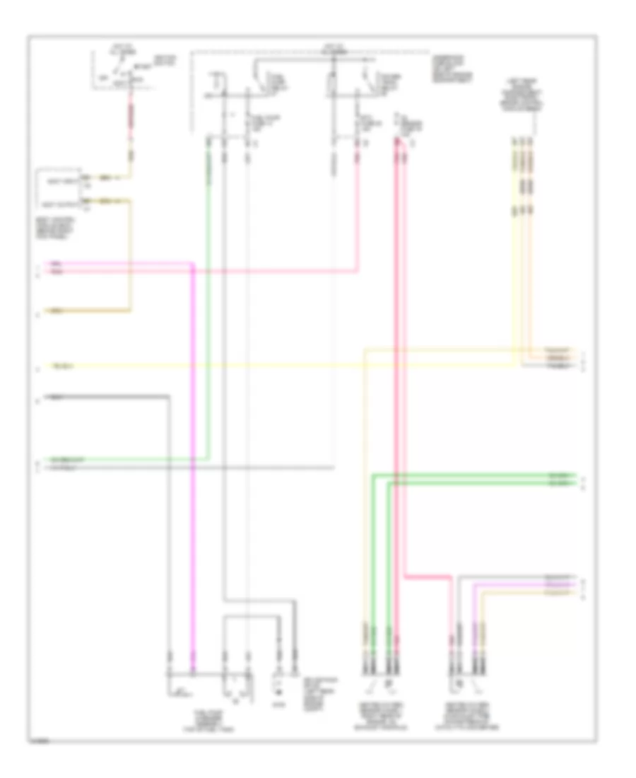
2.8L, Engine Performance Wiring Diagram (2 of 5) for Isuzu i-280 S 2006
List of elements for 2.8L, Engine Performance Wiring Diagram (2 of 5) for Isuzu i-280 S 2006:
- (2wd)
- (left rear engine compartment) electronic brake control module (ebcm)
- Accy
- Accy input
- Accy output
- Body control module (bcm) (behind right kick panel)
- Etc fuse 20 15a
- Fuel pump & sender assembly (top of fuel tank)
- Fuel pump fuse 13 15a
- Fuel pump relay
- G105
- Heated oxygen sensor (ho2s) 1 (right rear of engine, on exhaust manifold)
- Heated oxygen sensor (ho2s) 2 (in exhaust pipe, downstream of catalytic converter)
- Hot at all times
- Ignition switch
- Nca
- O2 sensor fuse 79 10a
- Off
- Pnk
- Power- train relay
- Run
- Splice pack sp105 (left rear side of engine compt)
- Start
- Underhood fuse block (on left side of engine compartment)
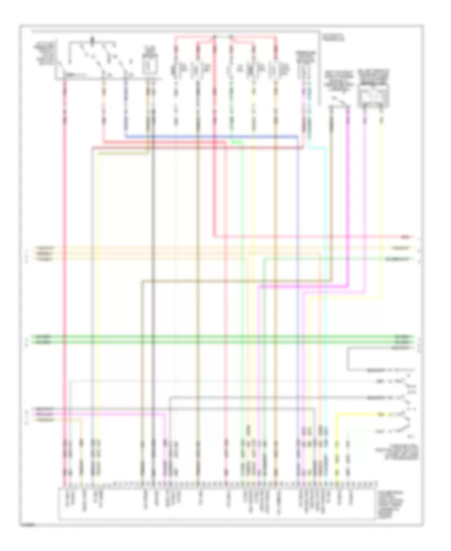
2.8L, Engine Performance Wiring Diagram (3 of 5) for Isuzu i-280 S 2006
List of elements for 2.8L, Engine Performance Wiring Diagram (3 of 5) for Isuzu i-280 S 2006:
- (2wd)
- (a/t)
- (bottom right side of engine) engine oil pressure (eop) switch
- (on left rear of transfer case) vehicle speed sensor (vss)
- 1-2 sol
- 2-3 sol
- 3-2 sol
- A/t fluid pressure manual valve position switch
- Automatic transaxle
- Del torque
- Evap purge
- Fluid temp sensor
- Ho2s 2 hi
- Ho2s 2 htr
- Ho2s 2 low
- Low oil sw
- Low ref
- Oil press
- Park/neutral position (pnp) switch (lower left side of transmission)
- Pc sol
- Pnk
- Powertrain control module (pcm) (right rear corner of engine compt)
- Pressure control solenoid
- Red
- Req torque
- Rev
- Tan
- Tcc pwm sol
- Tcc sol
- Tfp sw a
- Tfp sw b
- Tfp sw c
- Tft sens
- Tr sw a
- Tr sw b
- Tr sw c
- Tr sw p
- Vss sig hi
- Vss sig low
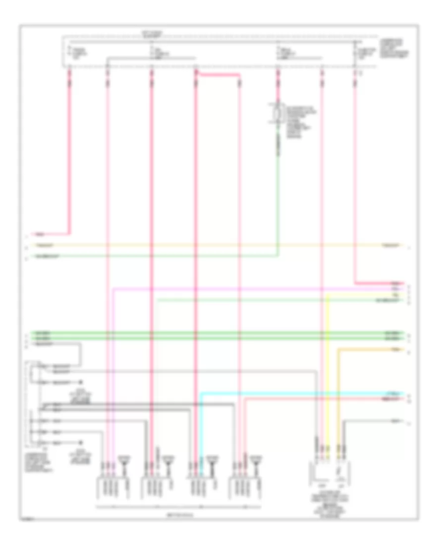
2.8L, Engine Performance Wiring Diagram (4 of 5) for Isuzu i-280 S 2006
List of elements for 2.8L, Engine Performance Wiring Diagram (4 of 5) for Isuzu i-280 S 2006:
- B11
- C11
- Control
- D11
- E11
- Erls fuse 27 15a
- Evaporative emission (evap) canister purge solenoid (lower left side of engine)
- F11
- G102 (at bottom left side of engine)
- G103 (at bottom left side of engine)
- Ground
- Hot in run & start
- Iat
- Ign fuse 23 15a
- Ignition
- Ignition coils
- Injector fuse 22 15a
- Intake air temperature (iat)/ mass air flow (maf) sensor (in air intake duct, top right of engine)
- Maf
- Nca
- Plug
- Pnk
- Spark plug
- Tan
- Trans fuse 24 10a
- Underhood fuse block (on left side of engine compartment)
- Underhood fuse block (on left side of engine compartment)
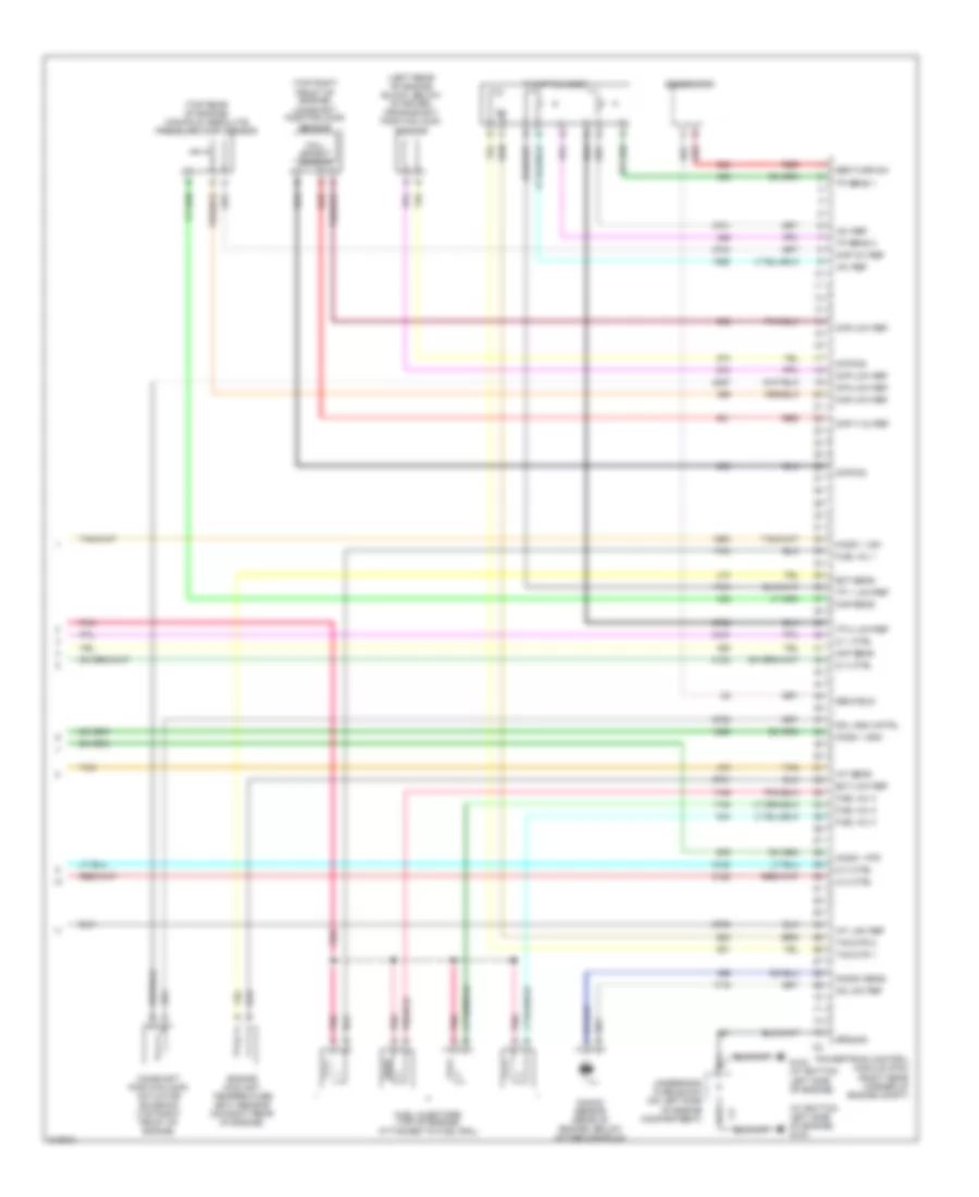
2.8L, Engine Performance Wiring Diagram (5 of 5) for Isuzu i-280 S 2006
List of elements for 2.8L, Engine Performance Wiring Diagram (5 of 5) for Isuzu i-280 S 2006:
- (at bottom left side of engine) g103
- (left rear of engine block, below starter) crankshaft position (ckp) sensor
- (top rear of engine) manifold absolute pressure (map) sensor
- (top right front of engine) camshaft position (cmp) sensor
- +5v ref
- A11
- B11
- Camshaft position (cmp) actuator solenoid (top right front of engine)
- Ckp low ref
- Ckp sig
- Cmp +12v ref
- Cmp low ref
- Cmp sig
- Cpa low ref
- Ect low ref
- Ect sens
- Engine coolant temperature (ect) sensor (on right rear of engine)
- Fuel inj 1
- Fuel inj 2
- Fuel inj 3
- Fuel inj 4
- Fuel injectors (top of engine, attached to fuel rail)
- G102 (at bottom left side of engine)
- Gen field
- Gen turn-on
- Generator
- Ground
- Hall effect sensor
- Ho2s 1 high
- Ho2s 1 htr
- Ho2s 1 low
- Iat low ref
- Iat sens
- Ic 1 ctrl
- Ic 2 ctrl
- Ic 3 ctrl
- Ic 4 ctrl
- Knock sens
- Knock sensor (rear of engine, below intake manifold)
- Ks low ref
- Maf sens
- Map +5v ref
- Map low ref
- Map sens
- Pnk
- Powertrain control module (pcm) (right rear corner of engine compt)
- Red
- Sol high cntrl
- Tac mtr 1
- Tac mtr 2
- Tan
- Throttle body
- Tp 1 low ref
- Tp 2 low ref
- Tp sens 1
- Tp sens 2
- Underhood fuse block (on left side of engine compartment)