ENGINE PERFORMANCE
3.5L
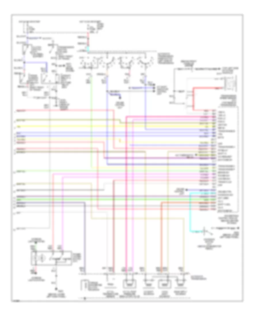
3.5L, Engine Performance Wiring Diagrams (1 of 4) for Isuzu Trooper LS 1998

List of elements for 3.5L, Engine Performance Wiring Diagrams (1 of 4) for Isuzu Trooper LS 1998:
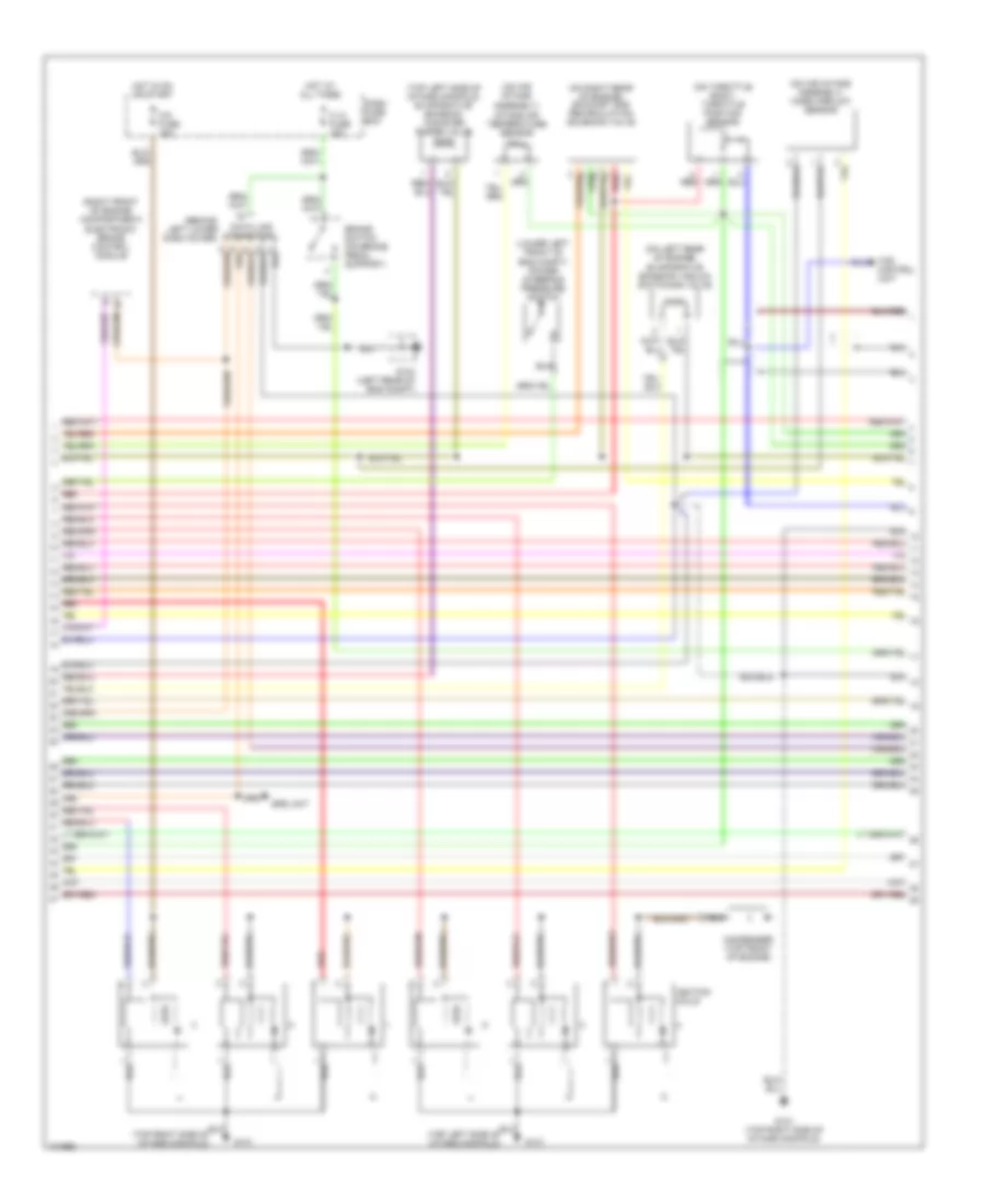
3.5L, Engine Performance Wiring Diagrams (2 of 4) for Isuzu Trooper LS 1998
List of elements for 3.5L, Engine Performance Wiring Diagrams (2 of 4) for Isuzu Trooper LS 1998:
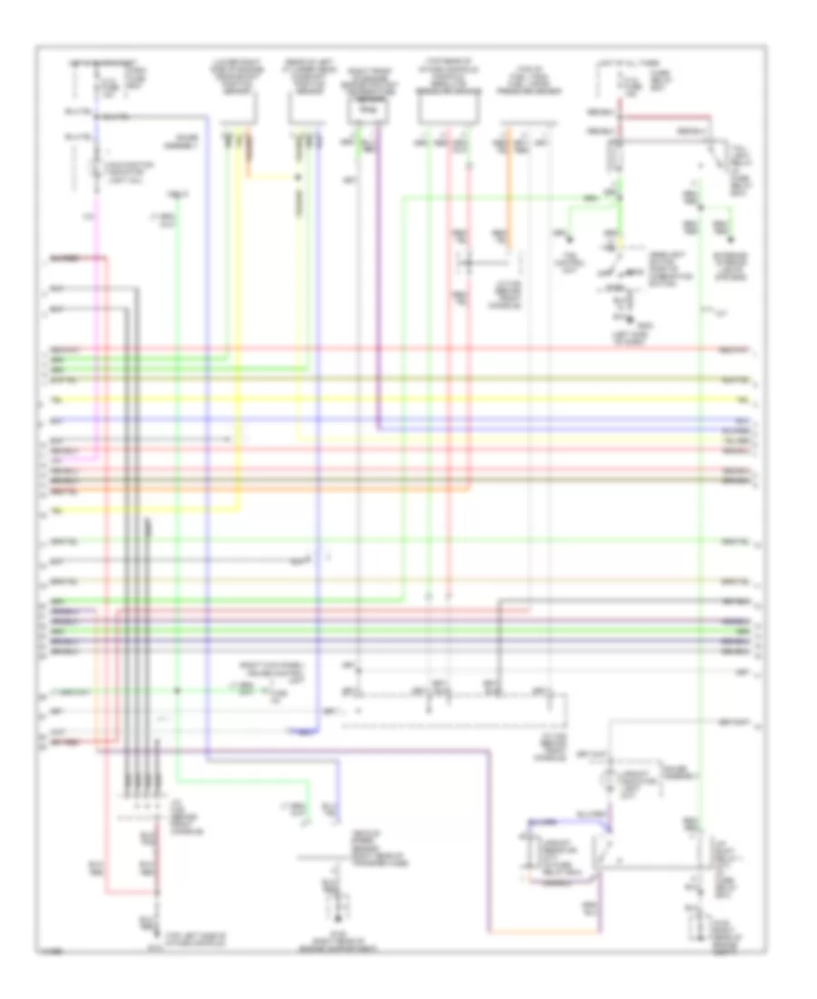
3.5L, Engine Performance Wiring Diagrams (3 of 4) for Isuzu Trooper LS 1998
List of elements for 3.5L, Engine Performance Wiring Diagrams (3 of 4) for Isuzu Trooper LS 1998:
3.5L, Engine Performance Wiring Diagrams (4 of 4) for Isuzu Trooper LS 1998
List of elements for 3.5L, Engine Performance Wiring Diagrams (4 of 4) for Isuzu Trooper LS 1998: