ENGINE PERFORMANCE
6.0L
6.0L, Engine Performance Wiring Diagrams (1 of 3) for Jaguar XJ12 1995

List of elements for 6.0L, Engine Performance Wiring Diagrams (1 of 3) for Jaguar XJ12 1995:
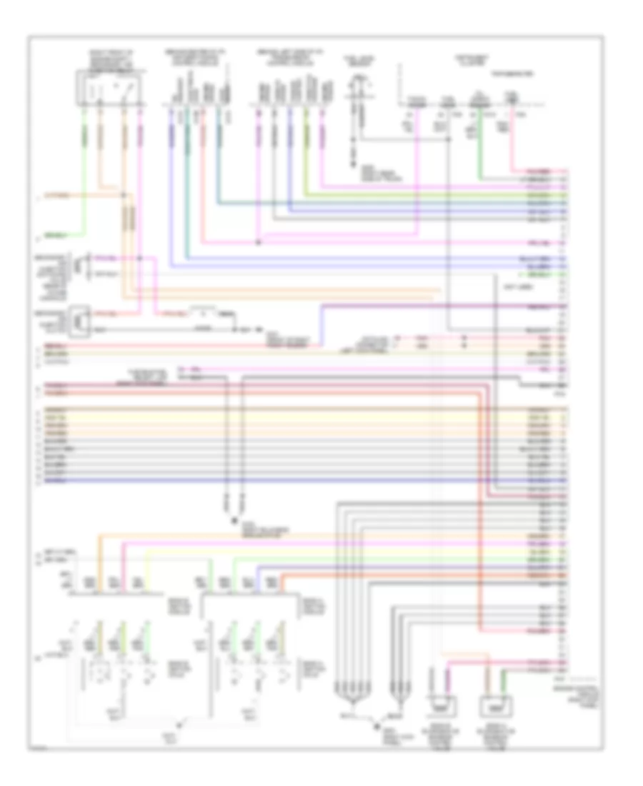
6.0L, Engine Performance Wiring Diagrams (2 of 3) for Jaguar XJ12 1995
List of elements for 6.0L, Engine Performance Wiring Diagrams (2 of 3) for Jaguar XJ12 1995:
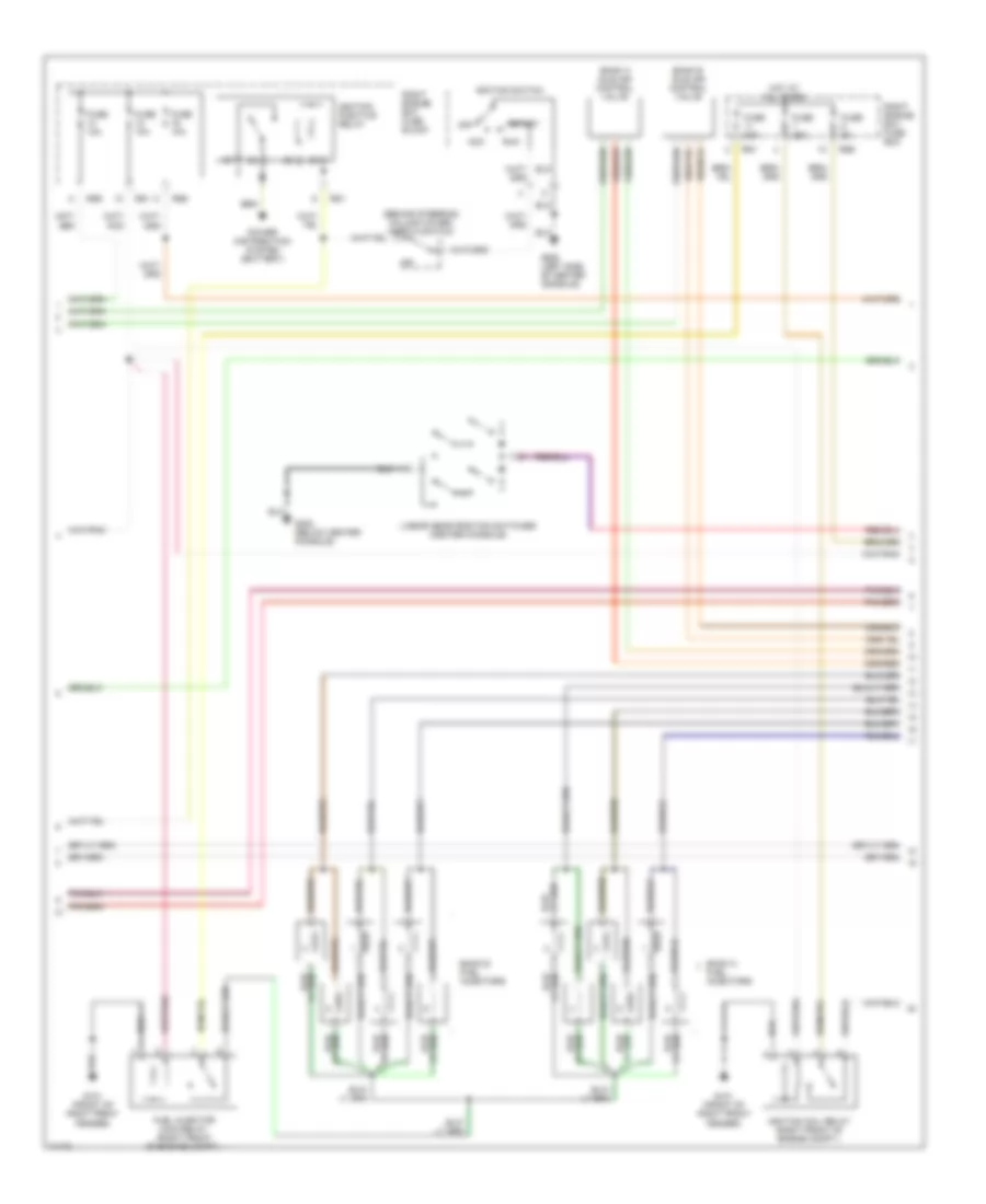
6.0L, Engine Performance Wiring Diagrams (3 of 3) for Jaguar XJ12 1995
List of elements for 6.0L, Engine Performance Wiring Diagrams (3 of 3) for Jaguar XJ12 1995: