ENGINE PERFORMANCE
4.0L
4.0L, Engine Performance Wiring Diagrams (1 of 3) for Jaguar XK8 1998

List of elements for 4.0L, Engine Performance Wiring Diagrams (1 of 3) for Jaguar XK8 1998:
- (eng compt, right hand enclosure)
- (next to driver's side fuse box) inertia switch
- Abs/traction control module (left front of side eng compt)
- Acc
- Air conditioning system
- Brake switch (top of brake pedal)
- Canister close valve (rear of left front wheelwell)
- Cruise control system
- Data link connector (below driver's side fuse box)
- Em10 em10
- Em11 em11
- Em12 em12
- Em19
- Em20
- Ems control relay
- Engine compartment fuse box
- Engine control module (in eng compt, in control module enclosure)
- Engine coolant temperature sensor (on rear of top eng hose)
- Engine management fuse box
- Fuel tank pressure sensor (in trunk, on fuel tank evaporative flange)
- Fuse 10a
- Fuse 5a
- G105
- G105 (eng compt, right hand enclosure)
- G202 (left side of dash)
- Gear selector illumination module (front of gear selector assembly)
- Hot at all times
- Ignition positive relay
- Igniton switch
- Lf6
- Lf7
- Major instrument pack
- Mass air flow sensor (rear of air cleaner)
- Mil ind
- Nca
- Off
- P/n
- Park brake switch (below parking brake lever)
- Pedal position & mechanical guard sensors
- Pnk
- Pnk pnk
- Red
- Red red
- Run
- Start
- Starting/ charging system
- Starting/charging system
- Throttle assembly
- Throttle motor
- Throttle position sensor
- Trans- mission control module (in eng compt, in control module enclosure)
- Transmission rotary switch (left side of transmission)
4.0L, Engine Performance Wiring Diagrams (2 of 3) for Jaguar XK8 1998
List of elements for 4.0L, Engine Performance Wiring Diagrams (2 of 3) for Jaguar XK8 1998:
- (eng compt, left hand enclosure)
- Bt11
- Camshaft position sensor (on rear "b" bank cylinder head)
- Crankshaft position sensor (in eng, rear of bed plate)
- Em19
- Engine management fuse box
- Evaporative emission control valve (left side of eng compt, on bulkhead extension
- Fuel pump
- Fuel pump relay
- Fuel tank
- Fuse 20a
- Fuse 30a
- Fuse 5a
- G104
- G401 (right front of trunk)
- Heated oxygen sensor "a" (upstream) ("a" bank catalytic converter)
- Heated oxygen sensor "b" (upstream) ("b" bank catalytic converter)
- Hot at all times
- Hot with igniton positive relay in trunk energized
- Nca
- Oxygen sensor "a" (downstream) ("a" bank catalytic converter)
- Oxygen sensor "b" (downstream) ("b" bank catalytic converter)
- Red
- Throttle motor power relay (in eng compt, in control module enclosure)
- Trunk fuse box (right rear of trunk)
- Vacuum switching valve 1 (behind right front wheelwell)
- Vacuum switching valve 2 (behind right front wheelwell)
- Vacuum switching valve 3 (behind right front wheelwell)
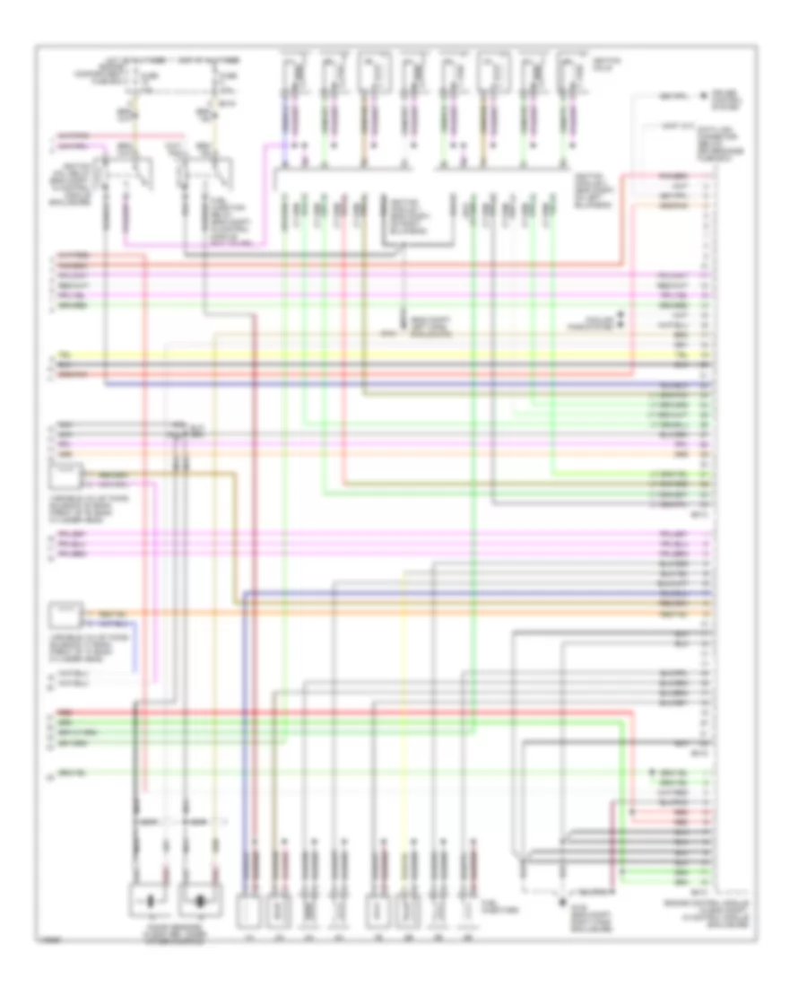
4.0L, Engine Performance Wiring Diagrams (3 of 3) for Jaguar XK8 1998
List of elements for 4.0L, Engine Performance Wiring Diagrams (3 of 3) for Jaguar XK8 1998:
- (eng compt, left hand enclosure)
- Cooling fans system
- Cruise control system
- Data link connector (below driver's side fuse box)
- Em13
- Em14
- Em15
- Em19
- Engine compartment fuse box
- Engine control module (in eng compt, in control module enclosure)
- Fuel injection relay (eng compt, in control module enclosure)
- Fuel injectors
- Fuse 10a
- G104
- G105 (eng compt, right hand enclosure)
- Hot at all times
- Ignition coil relay (eng compt, in control module enclosure)
- Ignition coils
- Ignition module 1 (eng compt, on right bulkhead)
- Ignition module 2 (eng compt, on left bulkhead)
- Knock sensors (in eng vee, under intake manifold)
- Nca
- Red
- Variable valve timing solenoid "a" bank (front of "a" bank cylinder head)
- Variable valve timing solenoid "b" bank (front of "b" bank cylinder head)