ENGINE PERFORMANCE
4.0L
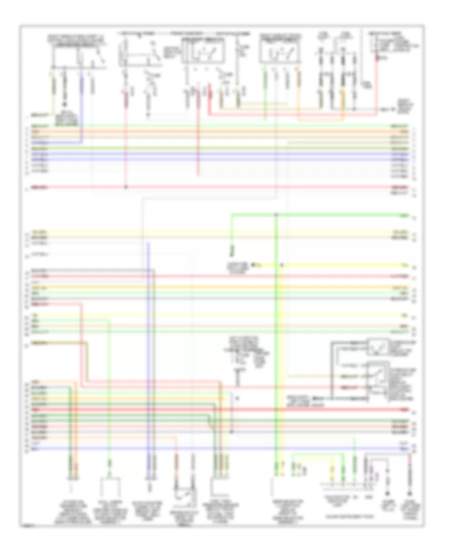
4.0L, Engine Performance Wiring Diagrams (1 of 4) for Jaguar XKR 2002

List of elements for 4.0L, Engine Performance Wiring Diagrams (1 of 4) for Jaguar XKR 2002:
- (early production vehicles have wire color codes that are different from that shown. use connector pin numbers for wire identification)
- (eng compt, right em1ar hand enclosure)
- (eng compt, right hand enclosure) em1bs
- (left side of transmission tunnel)
- (pin 13 not used)
- Acc
- Air conditioning system
- Braided
- Cooling fans system
- Cruise control system
- Data link connector (dlc) (below driver side fuse box)
- Ecm & tcm cooling fan
- Em19
- Em1al
- Em20
- Em80
- Em81
- Em82
- Ems control relay
- Engine control module (right rear side of eng compt, in control module enclosure)
- Engine coolant temperature sensor (rear of eng, in top hose)
- Engine management fuse box
- Fc3bl
- Fuse 10a
- Fuse 30a
- Fuse 5a
- Hot at all times
- Ignition switch
- Inertia switch (behind left side of dash)
- Manifold absolute pressure sensor
- Mass airflow sensor (rear of air cleaner)
- Nca
- Off
- P133
- P142
- P16
- Parking brake switch (below parking level)
- Pedal position sensor
- Red
- Run
- Start
- Starting/ charging system
- Throttle assembly
- Throttle motor
- Throttle position sensor
4.0L, Engine Performance Wiring Diagrams (2 of 4) for Jaguar XKR 2002
List of elements for 4.0L, Engine Performance Wiring Diagrams (2 of 4) for Jaguar XKR 2002:
- (eng compt, left hand enclosure) em2ar
- (right rear of eng compt, in control module enclosure) ignition coil relay
- (right rear of trunk) bt2al
- (right side of trunk) fuel pump 2 relay
- Brake switch (near top of brake pedal)
- Bt10
- Bt11
- Bt12
- Bt13
- Computer data lines system
- Driver side fuse box
- Dual linear switch (center console, at right side of gear selector assembly)
- Em1al (eng compt, right hand enclosure)
- Evap canister purge valve (behind left wheel arch liner)
- Fc25
- Fc3bl (left side of trans- mssion tunnel)
- Fc4br (left "a" pilla)
- Fc88
- Fuel pump 1
- Fuel pump 1 relay (4)
- Fuel pump 2
- Fuel tank
- Fuel tank pressure sensor (below trunk, on fuel tank evaporative flange)
- Fuse 10a
- Fuse 20a
- Fuse 5a
- Gear selector illumination module (front of gear selector assembly)
- Gnd
- High power protection module
- Hot at all times
- Hot w/ignition positive relay in driver side fuse box energized
- Ignition positive relay
- Intake air temperature sensor 2 (rear of bank a cylinder head, near intercooler)
- Intercooler pump (below air cleaner)
- Intercooler pump relay (right rear of eng compt, in control module enclosure)
- Major instrument pack
- Malfunction indicator lamp
- Nca
- Power fuse 250a
- Red
- Red bt63
- Trunk fuse box
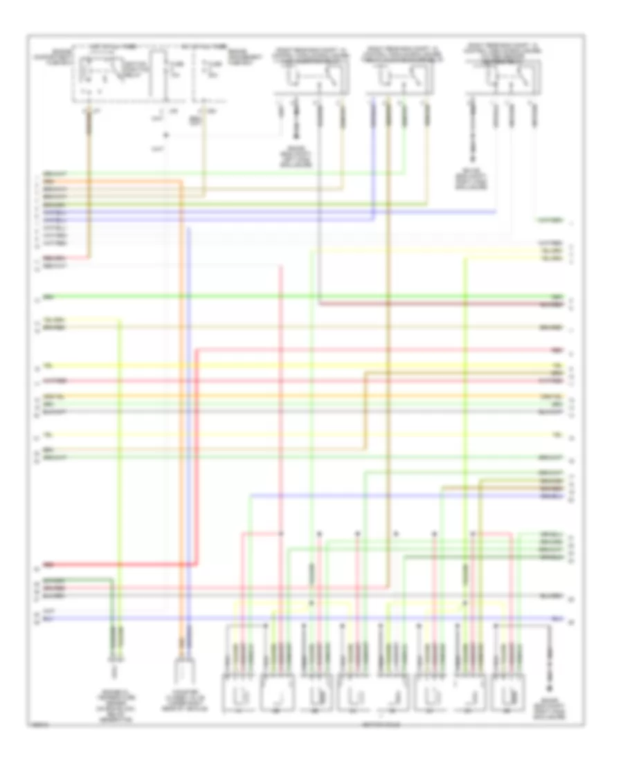
4.0L, Engine Performance Wiring Diagrams (3 of 4) for Jaguar XKR 2002
List of elements for 4.0L, Engine Performance Wiring Diagrams (3 of 4) for Jaguar XKR 2002:
- (right rear eng compt, in control module enclosure) fuel injection relay
- (right rear eng compt, in control module enclosure) oxygen sensor heaters relay
- (right rear eng compt, in control module enclosure) throttle motor power relay
- Canister closed valve (under right rear of vehicle)
- Em1ar (eng compt, right hand enclosure)
- Em2ar (eng compt, left hand enclosure)
- Em2ar (eng compt, right hand enclosure)
- Engine compartment fuse box
- Engine management fuse box
- Engine oil temperature sensor (on eng block, below generator)
- Fuse 10a
- Fuse 20a
- Hot at all times
- Ignition coils
- Ignition positive relay
- Lf6
- M20
- Red
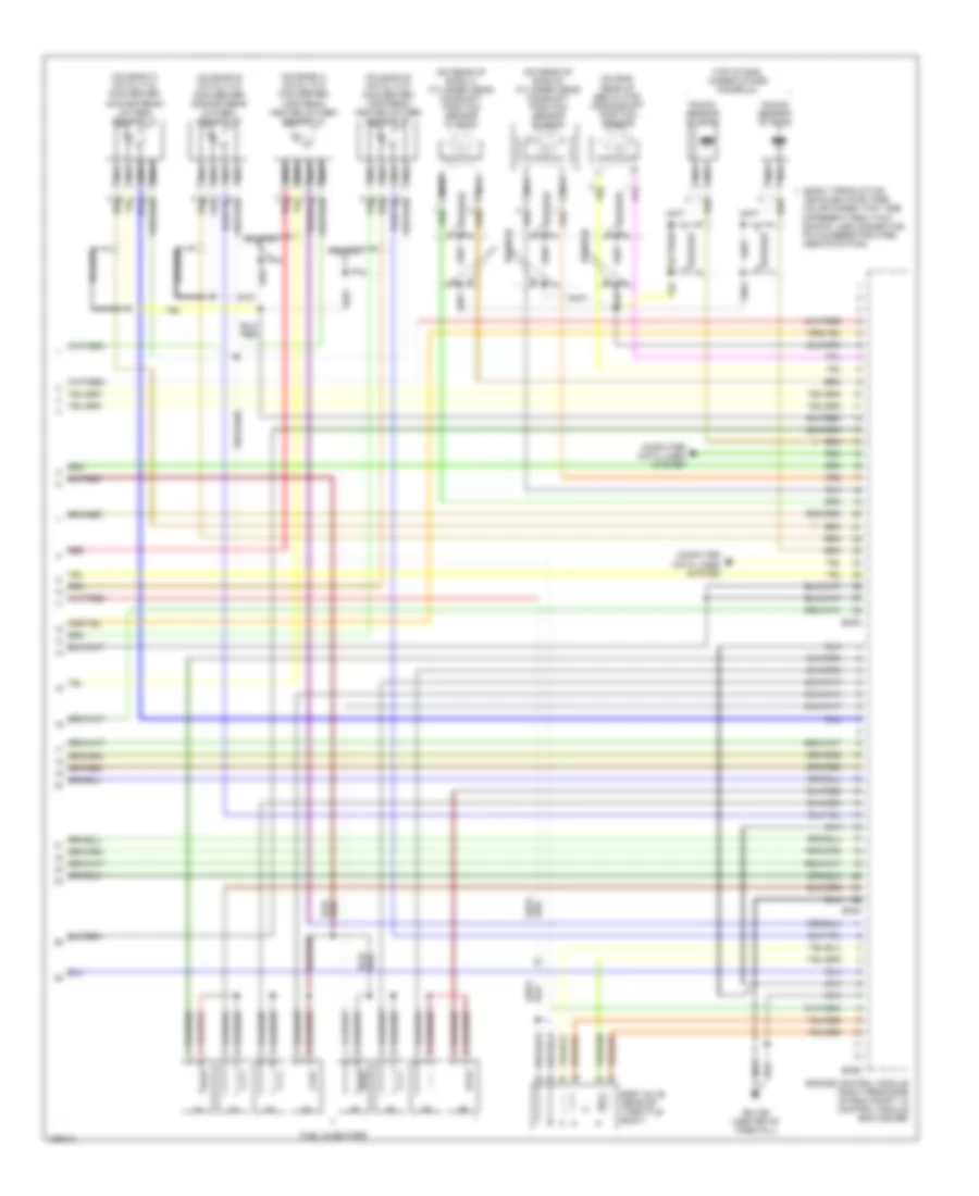
4.0L, Engine Performance Wiring Diagrams (4 of 4) for Jaguar XKR 2002
List of elements for 4.0L, Engine Performance Wiring Diagrams (4 of 4) for Jaguar XKR 2002:
- (early production vehicles have wire color codes that are different from that shown. use connector pin numbers for wire identification)
- (on bank a catalytic converter) downstream oxygen sensor "a"
- (on bank a catalytic converter) upstream heated oxygen sensor "a"
- (on bank b catalytic converter) downstream oxygen sensor "b"
- (on bank b catalytic converter) upstream heated oxygen sensor "b"
- (on eng, rear of bed plate) crankshaft position sensor
- (on rear of bank a cylinder head) camshaft position sensor "a" bank
- (on rear of bank b cylinder head) camshaft position sensor "b" bank
- (top of eng, under intake manifold)
- Braided
- Computer data lines system
- Egr valve (rear of throttle body)
- Em1ar (center of firewall)
- Em83
- Em84
- Em85
- Engine control module (right rear side of eng compt, in control module enclosure)
- Fuel injectors
- Knock sensor "a" bank
- Knock sensor "b" bank
- Nca
- Red