ENGINE PERFORMANCE
4.2L
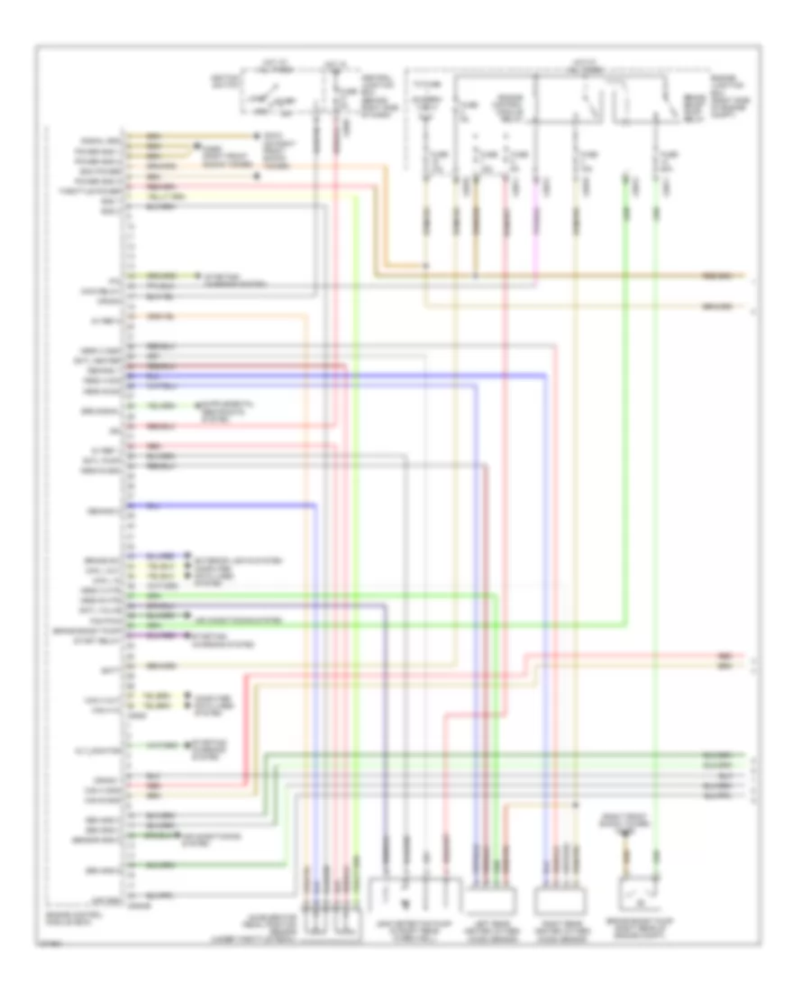
4.2L, Engine Performance Wiring Diagram (1 of 4) for Land Rover Range Rover HSE 2009

List of elements for 4.2L, Engine Performance Wiring Diagram (1 of 4) for Land Rover Range Rover HSE 2009:
- (right front shock tower) c0559
- 5v ref 1
- 5v ref 2
- Acc
- Accelerator pedal position sensor (under throttle pedal)
- Air conditioning system
- Alt_monitor
- Batt
- Brake boost pump
- Brake boost pump (right rear of engine compt)
- Brake boost pump relay
- Brake sw (a/l)
- C0560 (right front shock tower)
- C0570
- C0571
- C0572
- C0587
- C0634d
- C0635
- C0810 (on right front shock tower)
- Cam a gnd
- Cam b gnd
- Can h in
- Can h out
- Can l in
- Can l out
- Central junction box (behind right side of dash)
- Computer data lines system
- Crank
- Crank -
- Demand 1
- Demand 2
- Dmtl heater
- Dmtl pump
- Dmtl valve
- Ecm power
- Engine control module (ecm)
- Engine control module relay
- Engine junction box (right side of engine compt)
- Exterior lights system computer data lines system
- F/pump control
- F/pump monitor
- Fan pwm
- Fuse 10a
- Fuse 15a
- Fuse 20a
- Fuse 5a
- Gnd 1
- Gnd 2
- Hego a gnd
- Hego a htr
- Hego a sig
- Hego b gnd
- Hego b htr
- Hego b sig
- Hot at all times
- Hot in on
- Ign
- Ignition switch
- Leak detection pump (in right rear wheelwell)
- Left rear heated oxygen (ho2s) sensor
- Lock
- Maf gnd
- Main relay
- P/n
- Power gnd 1
- Power gnd 2
- Power gnd 3
- Red
- Right rear heated oxygen (ho2s) sensor
- Sen gnd 3
- Sen gnd 4
- Sen gnd 6
- Sensor gnd 5
- Signal gnd
- Srs signal
- Start
- Start relay-
- Starting/ charging system
- Throttle power
- To fuse (diagram 3 of 4)
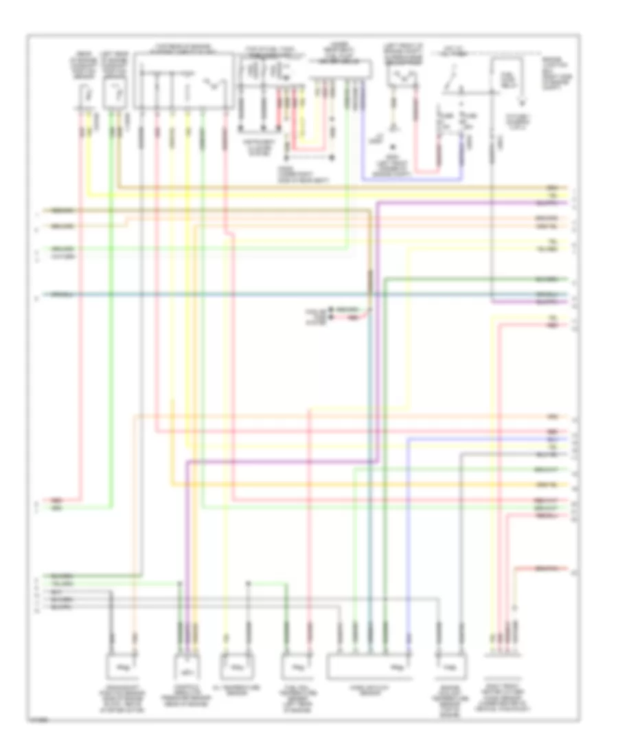
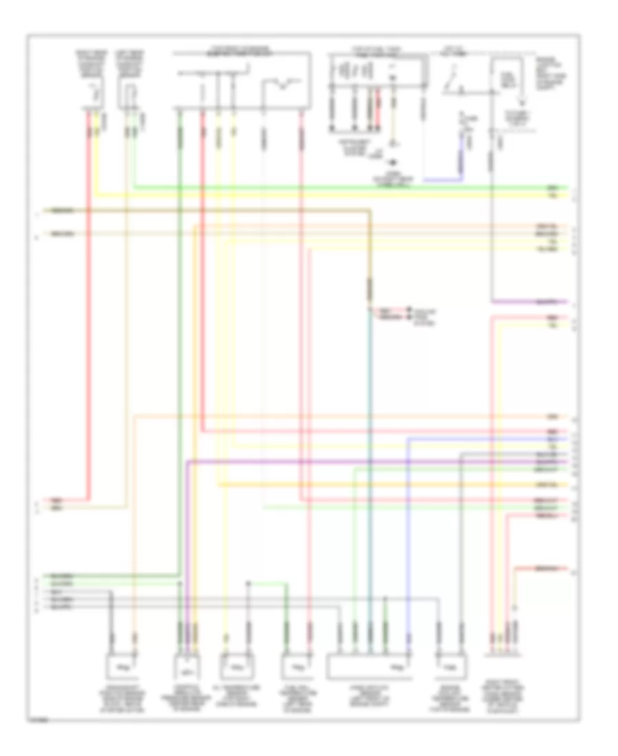
4.2L, Engine Performance Wiring Diagram (2 of 4) for Land Rover Range Rover HSE 2009
List of elements for 4.2L, Engine Performance Wiring Diagram (2 of 4) for Land Rover Range Rover HSE 2009:
- (left front of engine compt) supercharge coolant pump
- (left rear of engine) camshaft position sensor
- (rear of engine) camshaft position sensor
- (top of fuel tank)
- (top rear of engine) electric throttle unit
- (under rear seat) fuel pump driver module
- C0176d
- C0551 (left front corner of engine compt)
- C0570
- C0572
- C0809 (under right side of rear seat)
- C1463d
- Cooling fans system
- Crankshaft position sensor (side of engine block, above starter motor)
- Engine coolant temperature sensor (top of engine)
- Engine junction box (right side of engine compt)
- Fuel gauge
- Fuel pump relay
- Fuel rail temperature sensor (left rear of engine)
- Fuel tank unit
- Fuse 15a
- Fuse 25a
- Hot at all times
- Instrument cluster system
- J/c c0551
- Manifold absolute pressure sensor (rear of engine)
- Mass air flow sensor
- Oil temperature sensor
- Red
- Right front heated oxygen (ho2s) sensor (under center of vehicle, in exhaust)
- To fuse 1 (diagram 3 of 4)
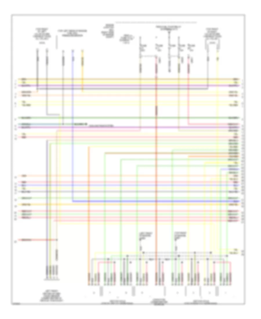
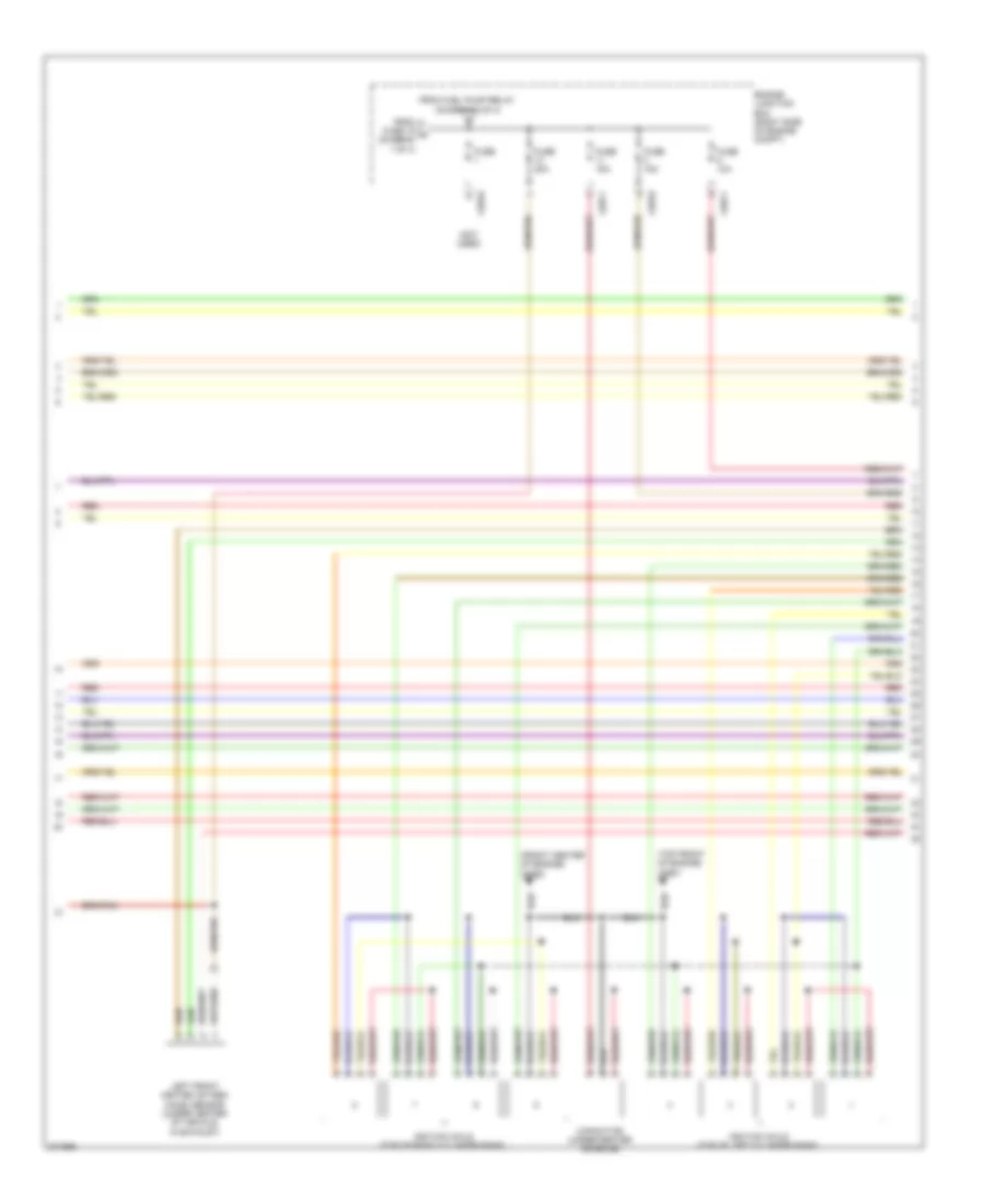
4.2L, Engine Performance Wiring Diagram (3 of 4) for Land Rover Range Rover HSE 2009
List of elements for 4.2L, Engine Performance Wiring Diagram (3 of 4) for Land Rover Range Rover HSE 2009:
- (left front of engine) c0562
- (not used)
- (top front of engine) c2651
- (top front of left valve cover) variable timing oil valve 2
- (top front of right valve cover) variable timing oil valve 1
- (top left rear of engine) fuel rail pressure sensor
- C0570
- C0571
- Capacitor (under center console)
- Cooling fans system
- Engine junction box (right side of engine compt)
- From fuel pump relay (diagram 2 of 4)
- From fuse 19 a (diagram 1 of 4)
- Fuse
- Fuse 10a
- Fuse 15a
- Fuse 20a
- Ignition coils (top of left cylinder bank)
- Ignition coils (top of right cylinder bank)
- Left front heated oxygen (ho2s) sensor (under center of vehicle, in exhaust)
- Red
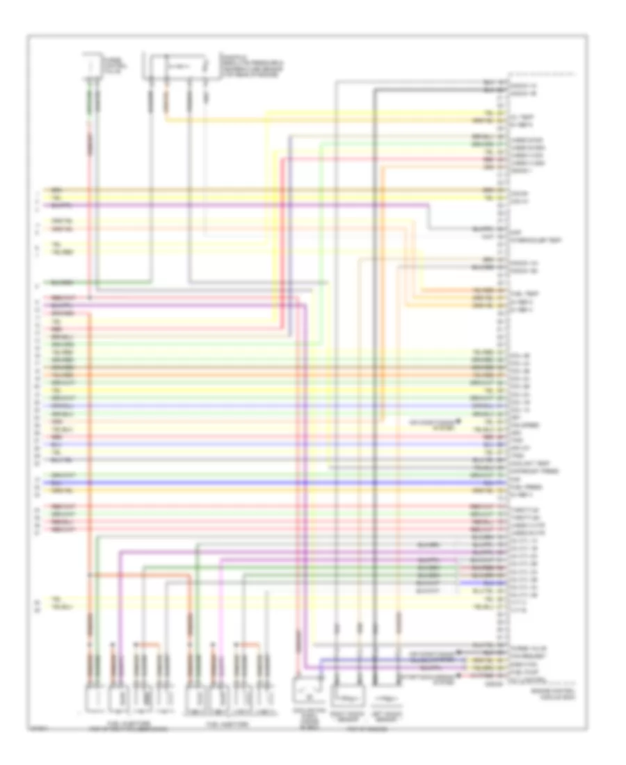
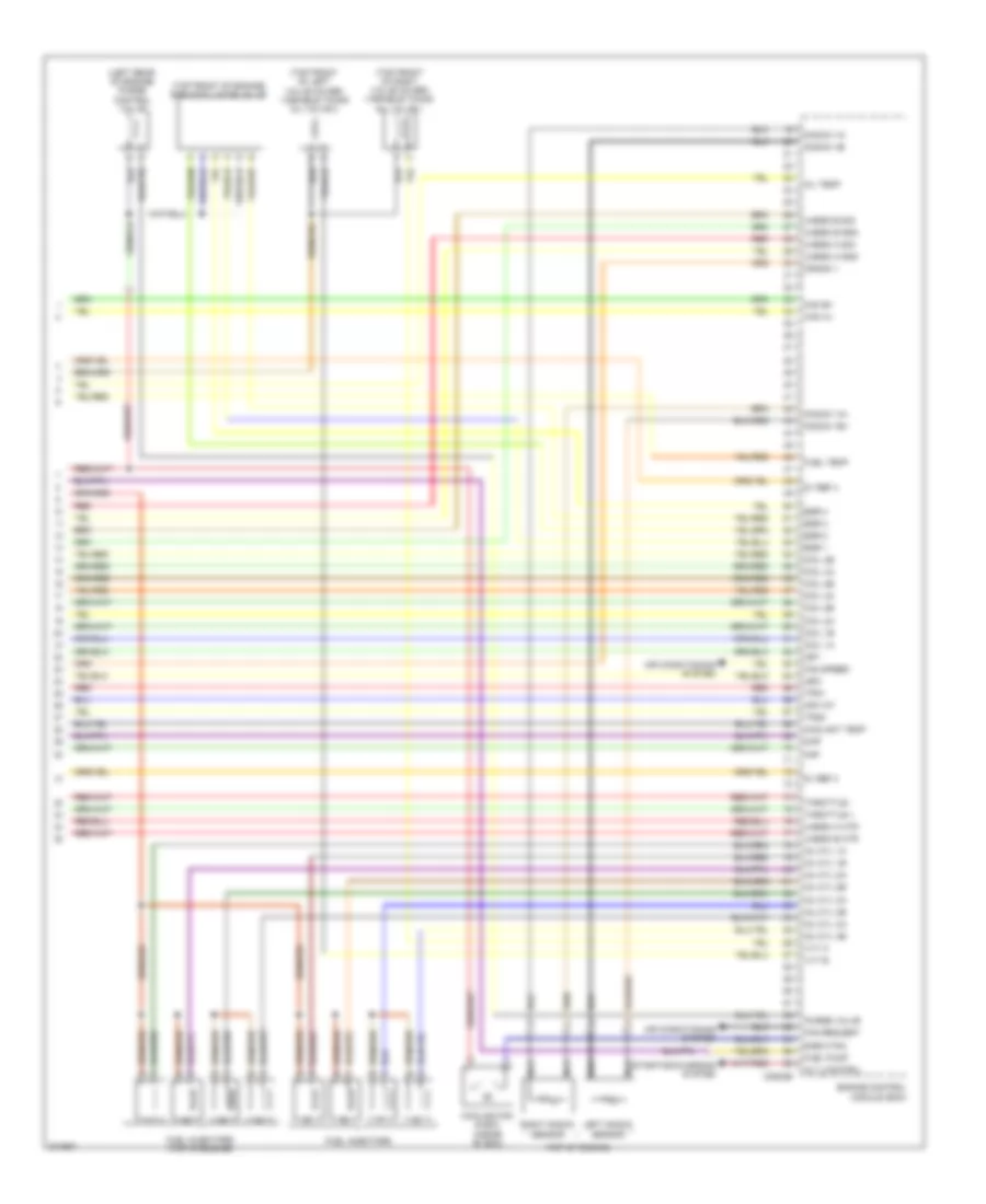
4.2L, Engine Performance Wiring Diagram (4 of 4) for Land Rover Range Rover HSE 2009
List of elements for 4.2L, Engine Performance Wiring Diagram (4 of 4) for Land Rover Range Rover HSE 2009:
- (top of engine)
- 5v ref 3
- 5v ref 4
- 5v ref 5
- 5v ref 6
- Afm iat
- Air conditioning system
- Alt_control
- C0634d
- Cam a+
- Cam b+
- Coil 1a
- Coil 1b
- Coil 2a
- Coil 2b
- Coil 3a
- Coil 3b
- Coil 4a
- Coil 4b
- Coolant temp
- Cooling fan e box (inside "e" box)
- Crank +
- E-box fan
- Engine control module (ecm)
- Fan request
- Fan speed
- Fuel injectors
- Fuel injectors (top of right cylinder bank)
- Fuel press
- Fuel pump
- Fuel temp
- Igf1
- Igf2
- Inj cyl 1a
- Inj cyl 1b
- Inj cyl 2a
- Inj cyl 2b
- Inj cyl 3a
- Inj cyl 3b
- Inj cyl 4a
- Inj cyl 4b
- Intercooler temp
- Knock 1a+
- Knock 1a-
- Knock 1b+
- Knock 1b-
- Left knock sensor
- Maf
- Manifold absolute pressure & temperature sensor (top rear of engine)
- Map
- Map/boost press
- Nca
- Oil temp
- Purge control valve
- Purge valve
- Red
- Right knock sensor
- Starting/charging system
- Throttle+
- Throttle-
- Tps1
- Tps2
- Uhego a gnd
- Uhego a htr
- Uhego a sig
- Uhego b gnd
- Uhego b htr
- Uhego b sig
- Vvt a
- Vvt b
4.4L
4.4L, Engine Performance Wiring Diagram (1 of 4) for Land Rover Range Rover HSE 2009
List of elements for 4.4L, Engine Performance Wiring Diagram (1 of 4) for Land Rover Range Rover HSE 2009:
- (right front shock tower) c0559
- 5v ref 1
- 5v ref 2
- Acc
- Accelerator pedal position sensor (under throttle pedal)
- Air conditioning system
- Alt_monitor
- Batt
- Brake boost pump
- Brake boost pump (right rear of engine compt)
- Brake boost pump relay
- Brake sw
- C0560 (right front shock tower)
- C0570
- C0571
- C0572
- C0587
- C0634b
- C0635
- C0810 (on right front shock tower)
- Cam a gnd
- Cam b gnd
- Can h in
- Can h out
- Can l in
- Can l out
- Central junction box (behind right side of dash)
- Computer data lines system
- Crank
- Crank -
- Demand 1
- Demand 2
- Dmtl heater
- Dmtl pump
- Dmtl valve
- Ecm power
- Engine control module (ecm)
- Engine control module relay
- Engine junction box (right side of engine compt)
- Exterior lights system computer data lines system
- Fan pwm
- Fuse 10a
- Fuse 15a
- Fuse 20a
- Fuse 5a
- Gnd 1
- Gnd 2
- Hego a gnd
- Hego a htr
- Hego a sig
- Hego b gnd
- Hego b htr
- Hego b sig
- Hot at all times
- Hot in on
- Ign
- Ignition switch
- Leak detection pump (in right rear wheelwell)
- Left rear heated oxygen (ho2s) sensor
- Lock
- Maf gnd
- Main relay
- P/n
- Power gnd 1
- Power gnd 2
- Power gnd 3
- Red
- Right rear heated oxygen (ho2s) sensor
- Sen gnd 3
- Sen gnd 4
- Sen gnd 6
- Sensor gnd 5
- Signal gnd
- Srs signal
- Start
- Start relay
- Starting/ charging system
- Throttle power
- To fuse (diagram 3 of 4)
4.4L, Engine Performance Wiring Diagram (2 of 4) for Land Rover Range Rover HSE 2009
List of elements for 4.4L, Engine Performance Wiring Diagram (2 of 4) for Land Rover Range Rover HSE 2009:
- (left rear of engine) camshaft position sensor
- (right rear of engine) camshaft position sensor
- (top front of engine) electric throttle unit
- (top of fuel tank)
- C0176b
- C0555 (on right rear wheelwell)
- C0570
- C0572
- C1463b
- Cooling fans system
- Crankshaft position sensor (side of engine block, above starter motor)
- Engine coolant temperature sensor (top of engine)
- Engine junction box (right side of engine compt)
- Fuel gauge
- Fuel pump relay
- Fuel rail temperature sensor (left rear of engine)
- Fuel tank unit
- Fuse 25a
- Hot at all times
- Instrument cluster system
- J/c c0555
- Manifold absolute pressure sensor (center rear of engine)
- Mass air flow sensor (left front of engine compt)
- Oil temperature sensor (top right side of engine)
- Red
- Right front heated oxygen (ho2s) sensor (under center of vehicle, in exhaust)
- To fuse 1 (diagram 3 of 4)
4.4L, Engine Performance Wiring Diagram (3 of 4) for Land Rover Range Rover HSE 2009
List of elements for 4.4L, Engine Performance Wiring Diagram (3 of 4) for Land Rover Range Rover HSE 2009:
- (front center of engine) c0562
- (not used)
- (top front of engine) c2651
- C0570
- C0571
- Capacitor (under center console)
- Engine junction box (right side of engine compt)
- From fuel pump relay (diagram 2 of 4)
- From fuse 19 a (diagram 1 of 4)
- Fuse
- Fuse 10a
- Fuse 15a
- Fuse 20a
- Ignition coils (top of left cylinder bank)
- Ignition coils (top of right cylinder bank)
- Left front heated oxygen (ho2s) sensor (under center of vehicle, in exhaust)
- Red
4.4L, Engine Performance Wiring Diagram (4 of 4) for Land Rover Range Rover HSE 2009
List of elements for 4.4L, Engine Performance Wiring Diagram (4 of 4) for Land Rover Range Rover HSE 2009:
- (left rear of engine) purge control valve
- (top front of engine) egr modulator valve
- (top front of left valve cover) variable timing oil valve 2
- (top front of right valve cover) variable timing oil valve 1
- (top of engine)
- 5v ref 3
- 5v ref 4
- Afm iat
- Air conditioning system
- Alt_control
- C0634b
- Cam a+
- Cam b+
- Coil 1a
- Coil 1b
- Coil 2a
- Coil 2b
- Coil 3a
- Coil 3b
- Coil 4a
- Coil 4b
- Coolant temp
- Cooling fan e box (inside "e" box)
- Crank +
- E-box fan
- Egr 1
- Egr 2
- Egr 3
- Egr 4
- Engine control module (ecm)
- Fan request
- Fan speed
- Fuel injectors
- Fuel injectors (top of engine)
- Fuel pump
- Fuel temp
- Igf1
- Igf2
- Inj cyl 1a
- Inj cyl 1b
- Inj cyl 2a
- Inj cyl 2b
- Inj cyl 3a
- Inj cyl 3b
- Inj cyl 4a
- Inj cyl 4b
- Knock 1a+
- Knock 1a-
- Knock 1b+
- Knock 1b-
- Left knock sensor
- Maf
- Map
- Nca
- Oil temp
- Purge valve
- Red
- Right knock sensor
- Starting/charging system
- Throttle +
- Throttle -
- Tps1
- Tps2
- Uhego a gnd
- Uhego a htr
- Uhego a sig
- Uhego b gnd
- Uhego b htr
- Uhego b sig
- Vvt a
- Vvt b