ENGINE PERFORMANCE
3.0L
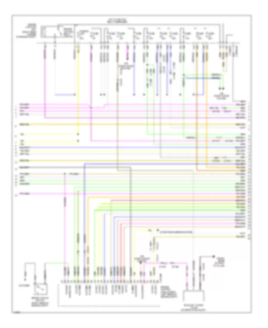
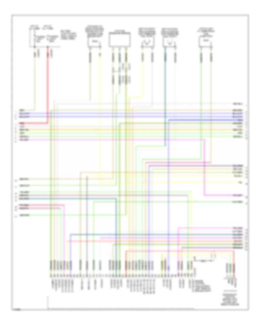
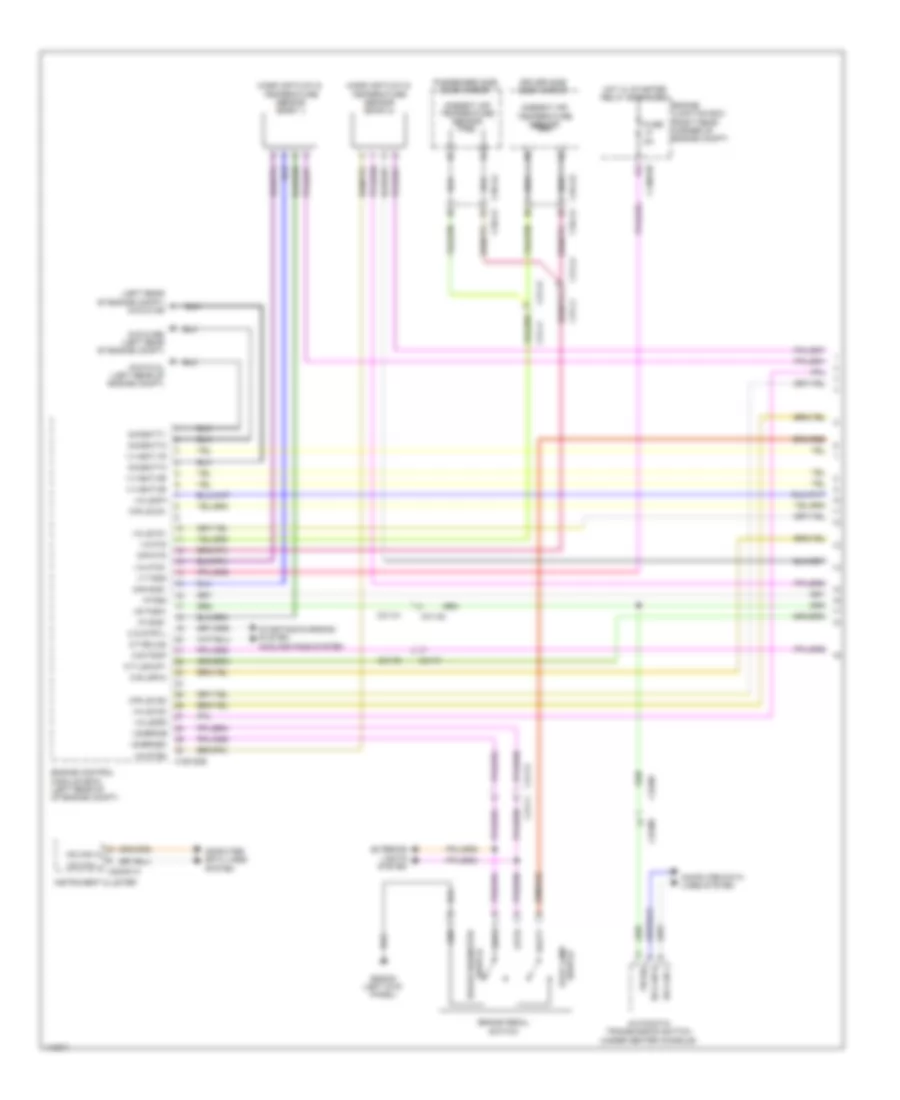
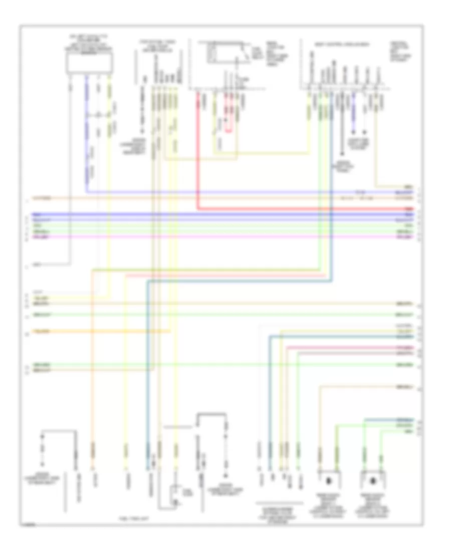
3.0L, Engine Performance Wiring Diagram (1 of 9) for Land Rover Range Rover HSE 2014

List of elements for 3.0L, Engine Performance Wiring Diagram (1 of 9) for Land Rover Range Rover HSE 2014:
- (left rear of engine compt) g1d121ar
- Ambient air temperature sensor
- Automatic transmission switch (under center console)
- Brake diagnostic switch
- Brake pedal switch
- C1e120b
- C2bp01f
- C2mc01a
- C31-a1
- C31-a2
- C31-f1
- C31-f2
- C31-j1
- C31-j2
- C31-l1
- C31-l2
- C32-m1
- C32-m2
- C3a-a1
- C3a-a2
- C3b-a1
- C3b-a2
- Central junction box (right end of dash)
- Computer data lines system
- Driver side door mirror
- Engine control module (ecm) (left rear of engine compt)
- Exterior lights system
- Fuse 5a
- G-g-batt1
- G-g-batt2
- G-g-batt3
- G-r-ams1
- G-r-ats
- G1d121al (left rear of engine compt)
- G1d121bs (left rear of engine compt)
- G2d233 (left kick panel)
- Hot at all times
- Hs can h
- Hs can h (pt)
- Hs can l
- Hs can l (pt)
- I-a-ats
- I-a-iats1
- I-a-iats2
- I-a-lscp1
- I-a-lscp2
- I-a-lsvn1
- I-a-lsvn2
- I-f-ams1
- I-f-pqs
- I-s-brkos
- I-s-brksw
- I-s-tnsw
- I-t-t50r
- Instrument cluster
- Mass air flow & temperature sensor (bank 1)
- Mass air flow & temperature sensor (bank 2)
- O-r-lsvg1
- O-r-lsvg2
- O-s-lsfh3
- O-s-strtl
- O-s-tdmp
- O-t-eclg2
- O-t-lshup1
- P/n sig
- Passenger side door mirror
- Starting/charging system
- Starting/charging system cooling fans system
- Stop lamp switch
- V-v-bat-1r
- V-v-bat-2r
- V-v-bat-3r
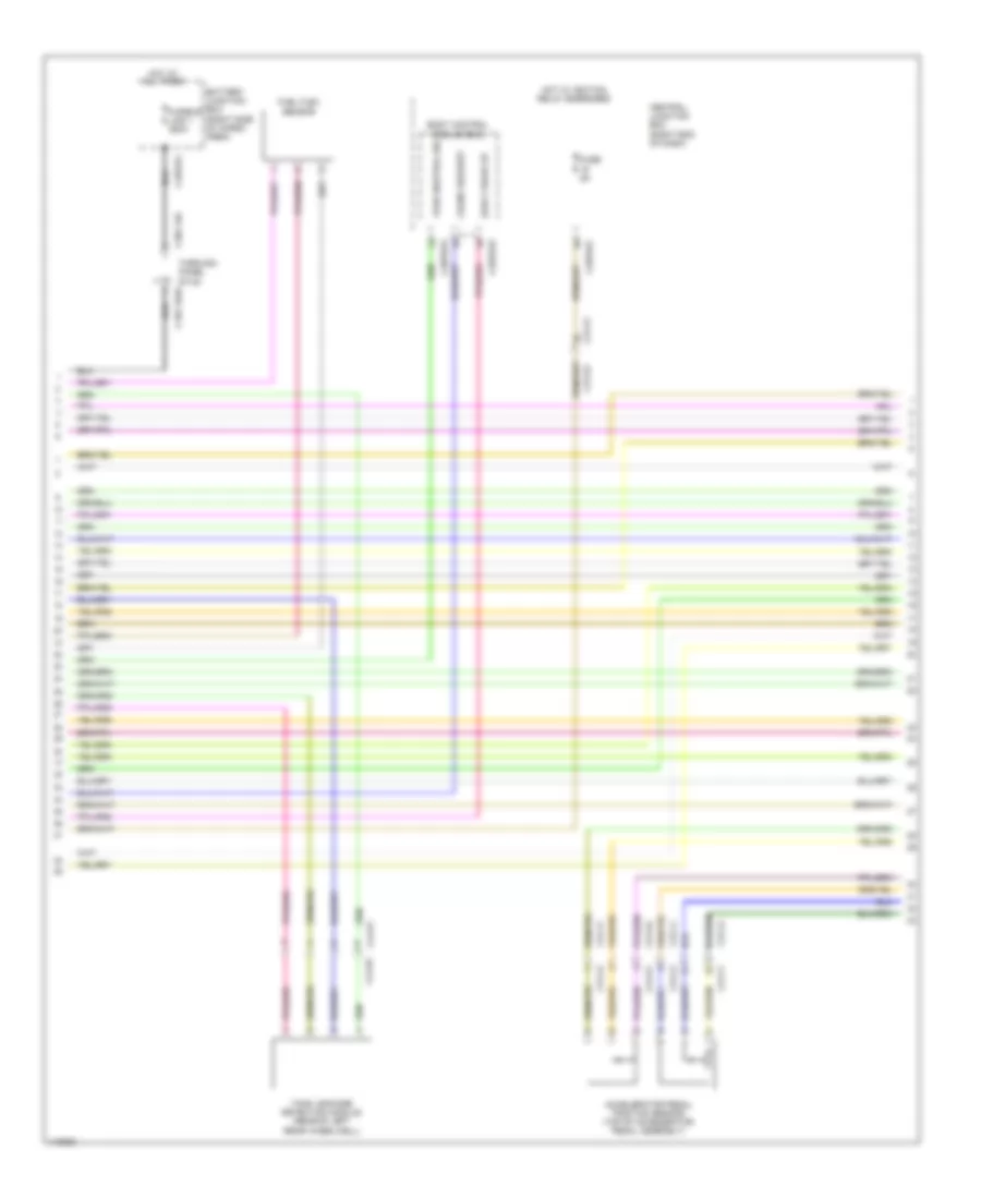
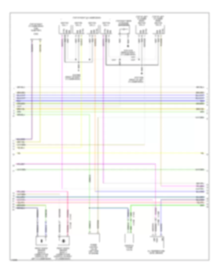
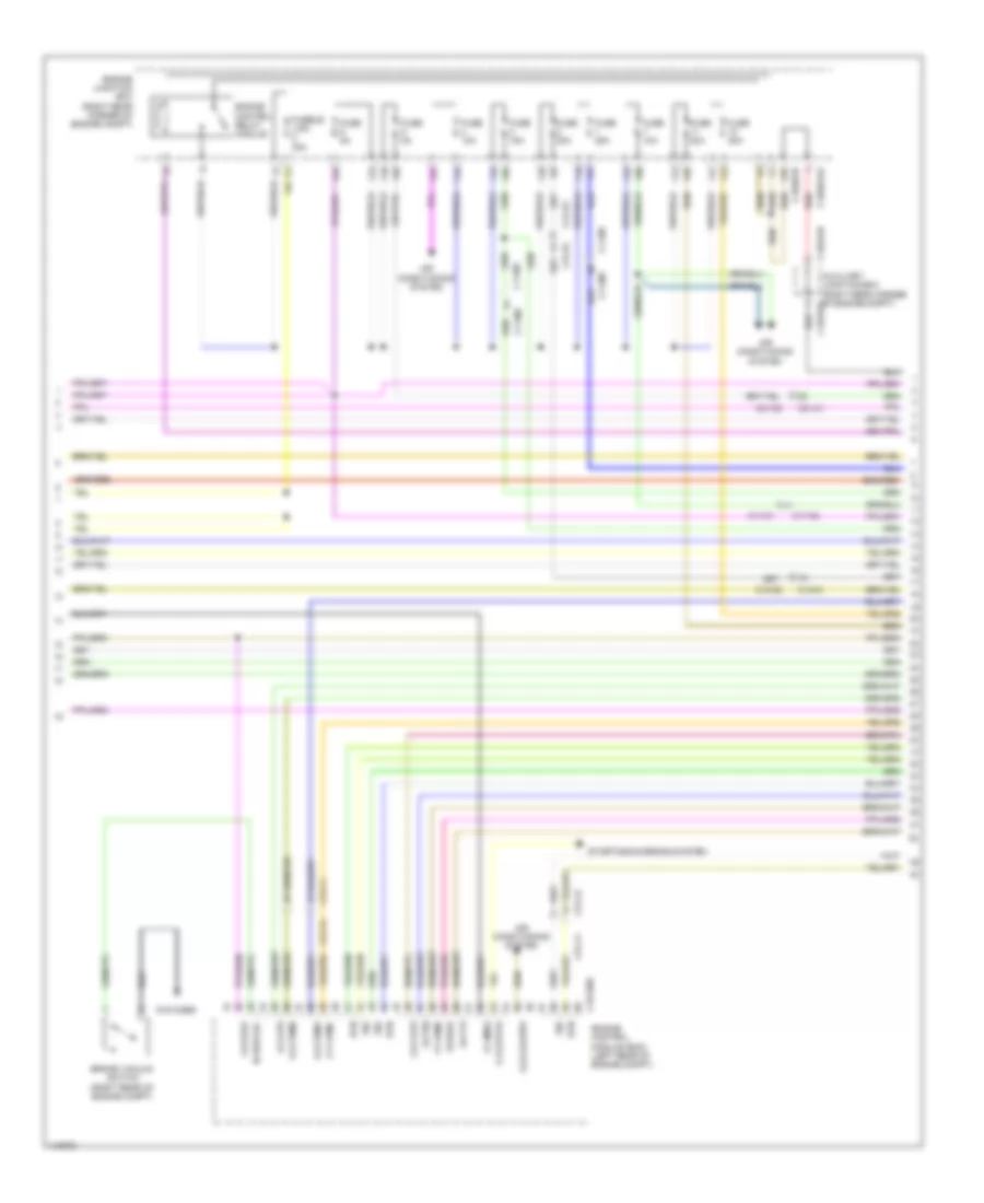
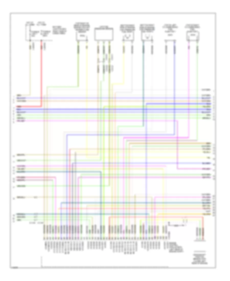
3.0L, Engine Performance Wiring Diagram (2 of 9) for Land Rover Range Rover HSE 2014
List of elements for 3.0L, Engine Performance Wiring Diagram (2 of 9) for Land Rover Range Rover HSE 2014:
- Air conditioning system
- Brake vacuum switch (right rear of engine compt)
- C11-m1
- C11-m2
- C13-c1
- C13-c2
- C1bb01ab
- C1bb01b
- C1e120b
- C31-a1
- C31-a2
- C31-e1
- C31-e2
- C31-f1
- C31-f2
- C31-j1
- C31-j2
- C31-k1
- C31-k2
- C44-b1
- C44-b2
- Engine control module (ecm) (left rear of engine compt)
- Engine control relay module
- Engine junction box (right rear corner of engine compt)
- Exhaust tuning valve (on rear of exhaust)
- Fuse 10a
- Fuse 15a
- Fuse 20a
- Fuse 25a
- Fuse 5a
- Fusible link 40a
- G-r-df01
- G-r-flps
- G-r-lsf1
- G-r-lsf3
- G-r-lsf4
- G1d123bs
- G4d351 (base of right "d" pillar)
- Hot w/ ignition relay energized
- I-a-flps
- I-a-lsf1
- I-a-lsf3
- I-a-lsf4
- I-f-ams2
- I-s-brk-vac
- I-s-t15
- I-s-t50
- I-s-wak
- I-t-fpmd
- O-s-cacwpr
- O-s-strth
- O-s-tdmh
- O-s-tdmv
- O-t-fpmc
- Starting/charging system
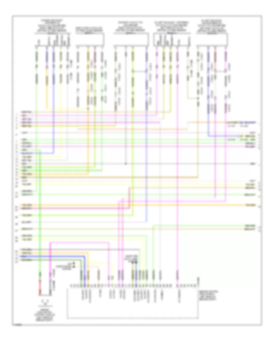
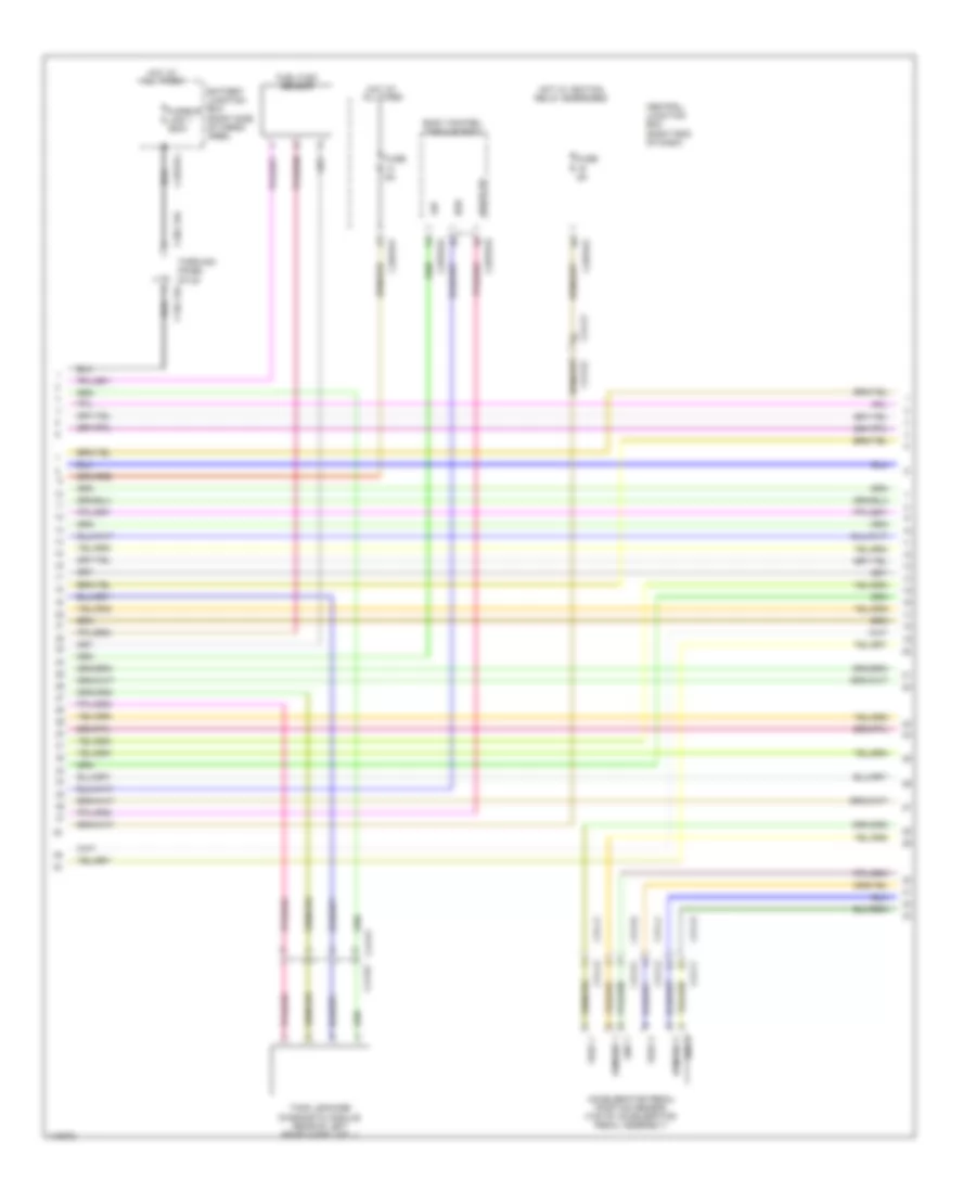
3.0L, Engine Performance Wiring Diagram (3 of 9) for Land Rover Range Rover HSE 2014
List of elements for 3.0L, Engine Performance Wiring Diagram (3 of 9) for Land Rover Range Rover HSE 2014:
- Accelerator pedal position sensor (top of accelerator pedal assembly)
- Battery junction box (right side of cargo area)
- Body control module (bcm)
- C1dc13ab
- C2bp01e
- C2bp01f
- C31-f1
- C31-f2
- C31-j1
- C31-j2
- C31-k1
- C31-k2
- C31-l1
- C31-l2
- C3bp01g
- C3dc13a
- C44-d1
- C44-d2
- C4bf01j
- Central junction box (right end of dash)
- Crank request
- Early wake up
- Fuel flex sensor
- Fuse 5a
- Fusible link 1 250a
- Hot at all times
- Hot w/ ignition relay energized
- Park neutral sig
- Tank leakage detection module (rear of left rear wheelwell)
- Through panel stud
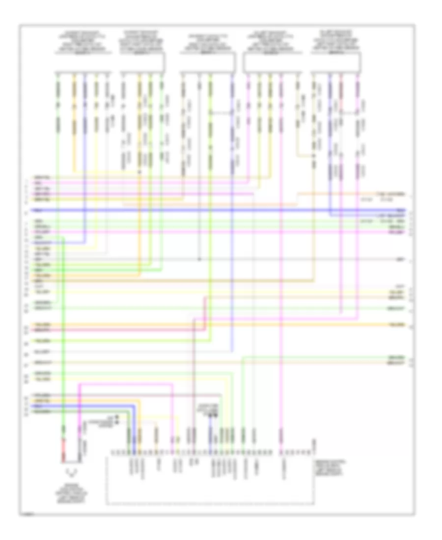
3.0L, Engine Performance Wiring Diagram (4 of 9) for Land Rover Range Rover HSE 2014
List of elements for 3.0L, Engine Performance Wiring Diagram (4 of 9) for Land Rover Range Rover HSE 2014:
- (in left exhaust, downstream of catalytic converter) left post catalyst heated oxygen sensor (bank 2)
- (in left exhaust, upstream of catalytic converter) left pre catalyst heated oxygen sensor (bank 2)
- (in right exhaust, upstream of catalytic converter) right pre catalyst heated oxygen sensor (bank 1)
- (on right catalytic converter) right mid catalyst heated oxygen sensor (bank 1)
- Air conditioning system
- B-d-canh1
- B-d-canl1
- C11-m1
- C11-m2
- C11-m2 c11-m1
- C13-c1
- C13-c2
- C13-d1
- C13-d2
- C1e120b
- C1e346
- C1e346m
- C31-a1
- C31-a2
- C31-f1
- C31-f2
- C31-j1
- C31-j2
- C31-k1
- C31-k2
- Computer data lines system
- Ctrl
- Engine control module (ecm) (left rear of engine compt)
- Engine cooling fan control module (left rear of engine compt)
- G-r-app1
- G-r-app2
- G-r-lsf2
- I-a-app1
- I-a-app2
- I-a-lsf2
- I-t-fss
- Nernst v
- O-s-mrly
- O-s-pcf
- O-t-evf
- O-t-lshup2
- O-v-5vapp1
- O-v-5vapp2
- O-v-5vflps
- Pmp current
- Pwp corrent
- Red
- Right post catalyst oxygen (ho2s) sensor (bank 1)
- Vertual gnd
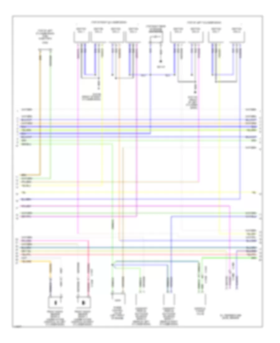
3.0L, Engine Performance Wiring Diagram (5 of 9) for Land Rover Range Rover HSE 2014
List of elements for 3.0L, Engine Performance Wiring Diagram (5 of 9) for Land Rover Range Rover HSE 2014:
- (on left catalytic converter) left mid catalyst heated oxygen sensor (bank 2)
- (top of fuel tank) fuel pump driver module
- Active
- C11-m1
- C11-m2
- C13-c1
- C13-c2
- C2bp01d
- C2bp01e
- C2bp01f
- C2bp01g
- C31-a1
- C31-a2
- C31-k1
- C31-k2
- C4br02a
- C4br02b
- C4mc11a
- C4mc11c
- Central junction box (right end of dash)
- Computer data lines system
- Diagnostic o/p
- Esd ground
- F/p control gnd
- Fuel pump
- Fuel pump relay
- Fuel tank unit
- Fuse 30a
- G2d238 (right kick panel)
- G3d389 (under right side of rear seat)
- Gnd
- Hs can h (pt)
- Hs can l (pt)
- Motor +
- Motor -
- Nca
- Passive
- Pos
- Pos 1
- Pwm
- Pwr
- Pwr gnd
- Rear junction box (right side of cargo area)
- Red
- Sender rtn
- Sensor gnd
- Supercharger bypass valve (top center front of engine)
- V ref
- Vbatt 3
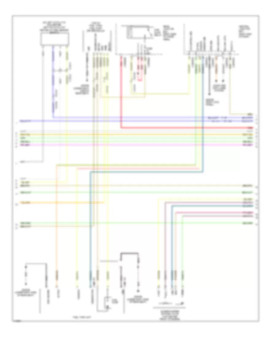
3.0L, Engine Performance Wiring Diagram (6 of 9) for Land Rover Range Rover HSE 2014
List of elements for 3.0L, Engine Performance Wiring Diagram (6 of 9) for Land Rover Range Rover HSE 2014:
- (bottom right side of engine) high pressure fuel pump 1
- (bottom right side of engine) high pressure fuel pump 2
- (top of left cylinder bank) fuel injector 6
- (top right of rear of engine) engine coolant temperature sensor (ect)
- Battery junction box (right side of cargo area)
- C1e121a
- C31-f1
- C31-f2
- C31-k1
- C31-k2
- C4bf01c
- C4bf01f
- Crankshaft position sensor (ckp) (lower left rear of engine)
- Engine control module (ecm) (left rear of engine compt)
- Fusible link 5 250a
- Fusible link 7 40a
- G-r-bps
- G-r-cbpp
- G-r-crs
- G-r-engts
- G-r-imps
- G-r-ocs
- Gnd
- Hot at all times
- I-a-bps
- I-a-cbpp
- I-a-ks1a
- I-a-ks1b
- I-a-ks2a
- I-a-ks2b
- I-a-railps
- I-f-crs
- I-p-casea
- Ign coil 2
- Ign coil 5
- Inj hs cyl 2a
- Inj hs cyl 3b
- Inj ls cyl 2a
- Inj ls cyl 3b
- Low fuel pressure sensor
- Nca
- O-p-fscvh1
- O-p-fscvh2
- O-p-fscvl1
- O-p-fscvl2
- O-t-cbppos
- O-t-tvapos
- O-v-5vcbpp
- O-v-crs
- Pwe 5v
- Red
- Sens
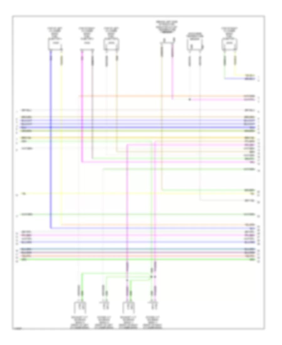
3.0L, Engine Performance Wiring Diagram (7 of 9) for Land Rover Range Rover HSE 2014
List of elements for 3.0L, Engine Performance Wiring Diagram (7 of 9) for Land Rover Range Rover HSE 2014:
- (top of left cylinder bank) ignition coil 5
- (top of left cylinder bank) ignition coil 6
- (top of right cylinder bank)
- (top of right cylinder bank) fuel injector 2
- (top right rear of engine) capacitor
- C11-af
- C11-an
- C11-m1 c11-m2
- C11af
- C11an
- Ctrl
- Front knock sensor (bank 1) (under intake manifold, on right cylinder bank)
- Front knock sensor (bank 2) (under intake manifold, on left cylinder bank)
- G1d1100e (front of left cylinder bank)
- G1d1101e (rear of right cylinder bank)
- G1d198e (front of right cylinder bank)
- Gnd
- Ign
- Ignition coil 1
- Ignition coil 2
- Ignition coil 3
- Ignition coil 4
- Manifold tuning valve
- Oil temperature level sensor
- Purge control valve (left side of engine)
- Sig
- Vref
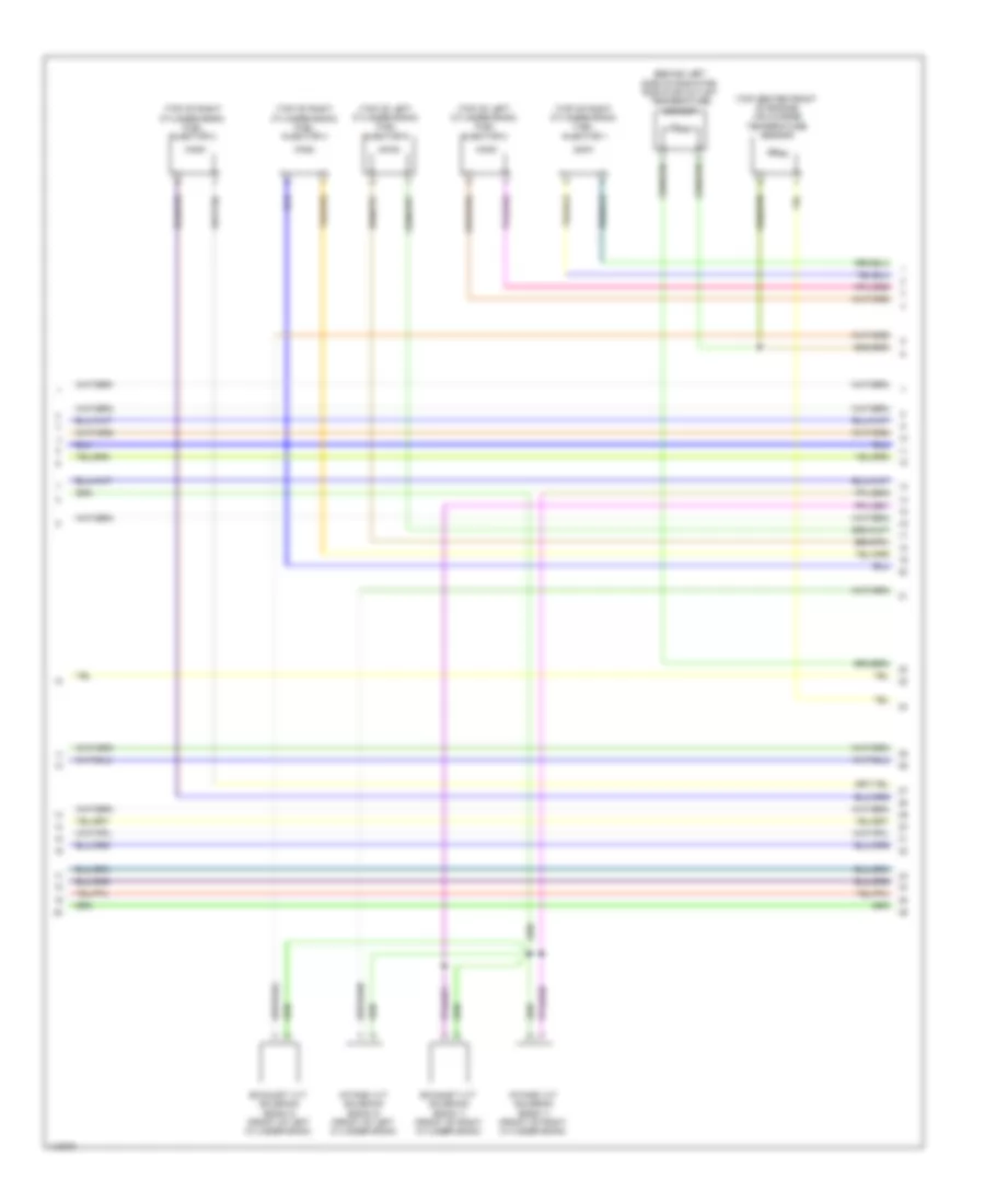
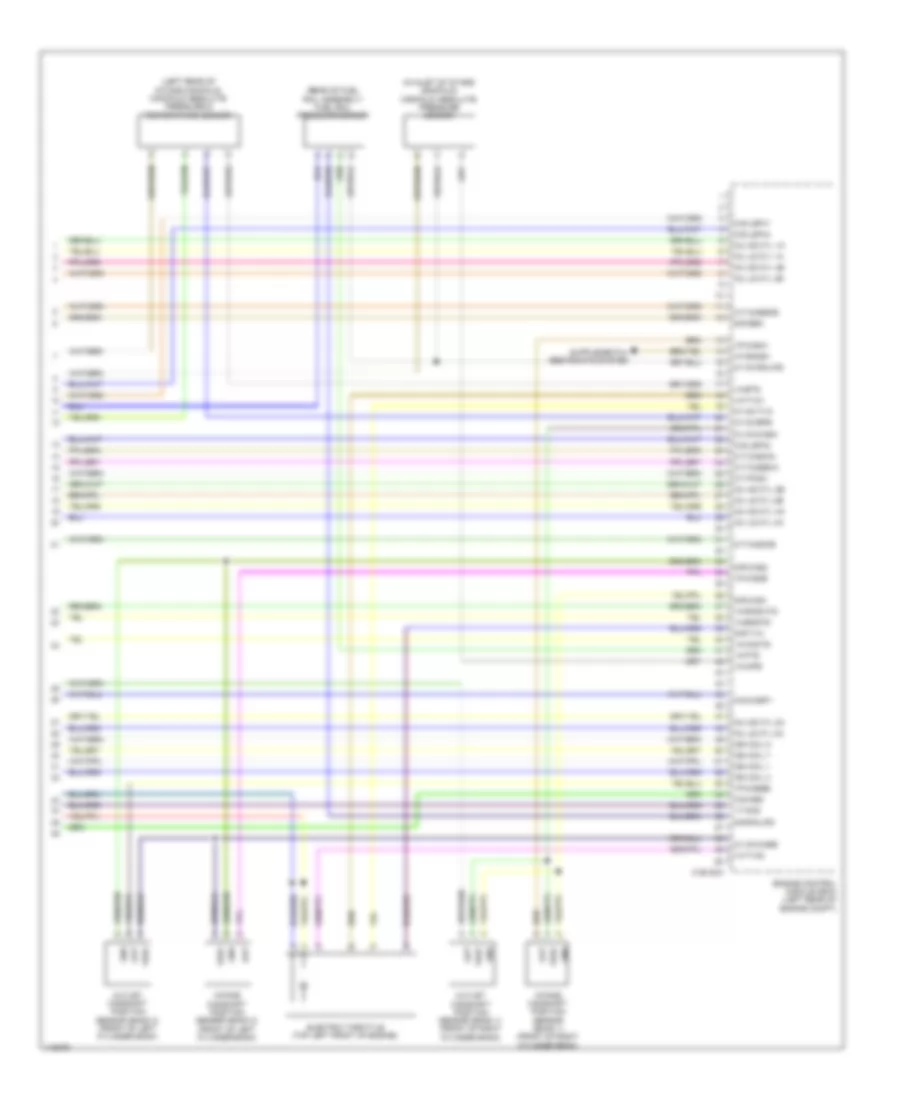
3.0L, Engine Performance Wiring Diagram (8 of 9) for Land Rover Range Rover HSE 2014
List of elements for 3.0L, Engine Performance Wiring Diagram (8 of 9) for Land Rover Range Rover HSE 2014:
- (behind left side of radiator) radiator outlet temperature sensor
- (top of left cylinder bank) fuel injector 4
- (top of left cylinder bank) fuel injector 5
- (top of right cylinder bank) fuel injector 1
- (top of right cylinder bank) fuel injector 3
- Air charge temperature sensor
- Ctrl
- Exhaust vvt solenoid (bank 1) (front of right cylinder bank)
- Exhaust vvt solenoid (bank 2) (front of left cylinder bank)
- Gnd
- Intake vvt solenoid (bank 1) (front of right cylinder bank)
- Intake vvt solenoid (bank 2) (front of left cylinder bank)
- Sig
- Sply
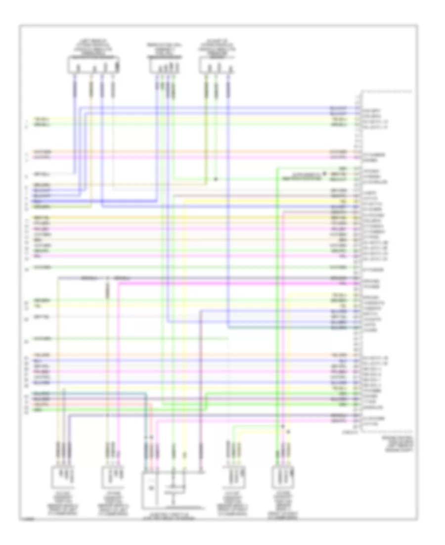
3.0L, Engine Performance Wiring Diagram (9 of 9) for Land Rover Range Rover HSE 2014
List of elements for 3.0L, Engine Performance Wiring Diagram (9 of 9) for Land Rover Range Rover HSE 2014:
- (in inlet of intake manifold) manifold absolute pressure sensor
- (left rear of intake manifold) manifold absolute pressure & temperature sensor
- (rear of fuel rail assembly) fuel rail pressure sensor
- C1e121a
- Electric throttle (top left front of engine)
- Engine control module (ecm) (left rear of engine compt)
- G-r-cas1
- G-r-cas2
- G-r-railps
- G-r-sen
- G-r-tva
- Gnd
- I-a-bts
- I-a-cacts
- I-a-engts
- I-a-fts
- I-a-imps
- I-a-radwts
- I-a-tva1
- I-a-tva2
- I-f-crash
- I-p-caseb
- I-p-casia
- I-p-casib
- I-t-ocs
- Ign coil 1
- Ign coil 3
- Ign coil 4
- Ign coil 6
- Inj hs cyl 1a
- Inj hs cyl 1b
- Inj hs cyl 2b
- Inj hs cyl 3a
- Inj ls cyl 1a
- Inj ls cyl 1b
- Inj ls cyl 2b
- Inj ls cyl 3a
- Intake camshaft position sensor (bank 1) (front of right cylinder bank)
- Intake camshaft position sensor (bank 2) (front of left cylinder bank)
- O-s-ass
- O-s-lsfh1
- O-s-lsfh2
- O-s-lsfh4
- O-t-caseca
- O-t-casecb
- O-t-casica
- O-t-casicb
- O-t-pcsv
- O-v-5vbps
- O-v-5vcasa
- O-v-5vcasb
- O-v-5vrailps
- O-v-5vtva
- Outlet camshaft position sensor (bank 1) (front of right cylinder bank)
- Outlet camshaft position sensor (bank 2) (front of left cylinder bank)
- Pwr 5v
- Sens
- Sensor
- Sig
- Temp
- Vref
5.0L SC
5.0L SC, Engine Performance Wiring Diagram (1 of 9) for Land Rover Range Rover HSE 2014
List of elements for 5.0L SC, Engine Performance Wiring Diagram (1 of 9) for Land Rover Range Rover HSE 2014:
- (left rear of engine compt) g1d121ar
- Ambient air temperature sensor
- Automatic transmission switch (under center console)
- Brake diagnostic
- Brake pedal switch
- C1bboib
- C1e120b
- C2mc01a
- C31-a1
- C31-a2
- C31-f1
- C31-f2
- C31-j1
- C31-j2
- C31-l1
- C31-l2
- C32-m1
- C32-m2
- C3a-a1
- C3a-a2
- C3b-a1
- C3b-a2
- Computer data lines system
- Driver side door mirror
- Engine control module (ecm) (left rear of of engine compt)
- Engine junction box (right rear corner of engine compt)
- Exterior lights system
- Fuse 5a
- G-g-batt1
- G-g-batt2
- G-g-batt3
- G-r-ams1
- G-r-ats
- G1d121al (left rear of engine compt)
- G1d121bs (left rear of engine compt)
- G2d233 (left kick panel)
- Gnd
- Hot w/ starter relay energized
- Hs can h
- Hs can l
- I-a-ats
- I-a-iats1
- I-a-iats2
- I-a-lscp1
- I-a-lscp2
- I-a-lsvn1
- I-a-lsvn2
- I-f-ams1
- I-f-fqs
- I-s-brkos
- I-s-brksw
- I-s-tnsw
- I-t-t50r
- Instrument cluster
- Mass air flow & temperature sensor (bank 1)
- Mass air flow & temperature sensor (bank 2)
- O s strtl
- O-r-lsvg1
- O-r-lsvg2
- O-s-lsfh3
- O-s-tdmp
- O-t-eclg2
- O-t-lshup1
- Outh
- Outl
- Passenger side door mirror
- Pn sig
- Starting/charging system cooling fans system
- Stop lamp switch
- Switch
- V-v-bat-1r
- V-v-bat-2r
- V-v-bat-3r
- Vbatt
5.0L SC, Engine Performance Wiring Diagram (2 of 9) for Land Rover Range Rover HSE 2014
List of elements for 5.0L SC, Engine Performance Wiring Diagram (2 of 9) for Land Rover Range Rover HSE 2014:
- Air conditioning system
- Auxiliary junction box (right rear corner of engine compt) c1bf01a
- Brake vacuum switch (right rear of engine compt)
- C11-m1
- C11-m2
- C13-c1
- C13-c2
- C1bb01aa
- C1bb01b
- C1bf01h
- C1e120b
- C31-f1
- C31-f2
- C31-j1
- C31-j2
- C31-k1
- C31-k2
- Engine control module (ecm) (left rear of engine compt)
- Engine control relay module
- Engine junction box (right rear corner of engine compt)
- Fuse 10a
- Fuse 15a
- Fuse 20a
- Fuse 25a
- Fuse 5a
- Fusible link 40a
- G-r-df01
- G-r-flps
- G1d123bs
- I-a-flps
- I-f-ams2
- I-s-t15
- I-s-t50
- I-s-wak
- I-t-fpmd
- Is brkvac
- O s strth
- O-s-cacwpr
- O-s-tdmh
- O-s-tdmv
- O-t-fpmc
- Red
- Rtn
- Sig
- Starting/charging system
5.0L SC, Engine Performance Wiring Diagram (3 of 9) for Land Rover Range Rover HSE 2014
List of elements for 5.0L SC, Engine Performance Wiring Diagram (3 of 9) for Land Rover Range Rover HSE 2014:
- Accelerator pedal position sensor (top of accelerator pedal assembly)
- Battery junction box (right side of cargo area)
- Body control module (bcm)
- C1dc13a
- C2bp01e
- C2bp01f
- C2bp01g
- C31-f1
- C31-f2
- C31-j1
- C31-j2
- C31-k1
- C31-k2
- C31-l1
- C31-l2
- C3dc13a
- C44-d1
- C44-d2
- C4bf01j
- Central junction box (right end of dash)
- Demand 1
- Demand 2
- Dip
- Fuel flex sensor
- Fuse 5a
- Fusible link 1 250a
- Gnd 1
- Gnd 2
- Hot at all times
- Hot w/ ignition relay energized
- Hsd
- Tank leakage diagnostic module (rear of left rear wheelwell)
- Through panel stud
- Vref 1
- Vref 2
- Wake up
5.0L SC, Engine Performance Wiring Diagram (4 of 9) for Land Rover Range Rover HSE 2014
List of elements for 5.0L SC, Engine Performance Wiring Diagram (4 of 9) for Land Rover Range Rover HSE 2014:
- (in left exhaust, downstream of catalytic converter) left post catalyst heated oxygen sensor (bank 2)
- (in left exhaust, upstream of catalytic converter) left pre catalyst heated oxygen sensor (bank 2)
- (in right exhaust, downstream of catalytic converter) right post catalyst oxygen (ho2s) sensor (bank 1)
- (in right exhaust, upstream of catalytic converter) right pre catalyst heated oxygen sensor (bank 1)
- (on right catalytic converter) right mid catalyst heated oxygen sensor (bank 1)
- Air conditioning system
- B-d-canh1
- B-d-canl1
- C11-m1
- C11-m2
- C11-m2 c11-m1
- C13-c1
- C13-c2
- C13-d1
- C13-d2
- C1e120b
- C1e346
- C1e346r
- C31-a1
- C31-a2
- C31-f1
- C31-f2
- C31-j1
- C31-j2
- C31-k1
- C31-k2
- Computer data lines system
- Engine control module (ecm) (left rear of engine compt)
- Engine cooling fan control module (left rear of engine compt)
- G-r-app1
- G-r-app2
- I-a-app1
- I-a-app2
- I-t-fss
- O-s-mrly
- O-s-pcf
- O-t-evf
- O-t-lshup2
- O-v-5vapp1
- O-v-5vapp2
- O-v-5vflps
- Red
- Rtn
- Sig
5.0L SC, Engine Performance Wiring Diagram (5 of 9) for Land Rover Range Rover HSE 2014
List of elements for 5.0L SC, Engine Performance Wiring Diagram (5 of 9) for Land Rover Range Rover HSE 2014:
- (on left catalytic converter) left mid catalyst heated oxygen sensor (bank 2)
- (top of fuel tank) fuel pump driver module
- Active
- Body control module (bcm)
- C11-m1
- C11-m2
- C13-c1
- C13-c2
- C2bp01d
- C2bp01e
- C2bp01f
- C2bp01g
- C31-a1
- C31-a2
- C31-k1
- C31-k2
- C4br02a
- C4br02b
- C4mc11a
- C4mc11c
- Central junction box (right end of dash)
- Computer data lines system
- Diagnostic o/p
- F/p control gnd
- Fsd filter gnd
- Fuel pump
- Fuel pump relay
- Fuel tank unit
- Fuse 30a
- G2d238 (right kick panel)
- G3d389 (under right side of rear seat)
- Gnd
- Hs can h
- Hs can l
- Motor +
- Motor -
- Passive
- Pwm
- Pwr
- Pwr gnd
- Rear junction box (right side of cargo area)
- Rear knock sensor (bank 1) (under intake manifold, on right cylinder bank)
- Rear knock sensor (bank 2) (under intake manifold, on left cylinder bank)
- Red
- Rfi gnd
- Sender rtn
- Sensor gnd
- Sig
- Supercharger bypass valve (top center front of engine)
- Tps 5v
- Vbatt 3
5.0L SC, Engine Performance Wiring Diagram (6 of 9) for Land Rover Range Rover HSE 2014
List of elements for 5.0L SC, Engine Performance Wiring Diagram (6 of 9) for Land Rover Range Rover HSE 2014:
- (bottom right side of engine) high pressure fuel pump 1
- (bottom right side of engine) high pressure fuel pump 2
- (top of left cylinder bank) fuel injector 7
- (top of right cylinder bank) fuel injector 3
- (top right of rear of engine) engine coolant temperature sensor
- Battery junction box (right side of cargo area)
- C11af
- C11an
- C1e120a
- C31-f1
- C31-f2
- C31-k1
- C31-k2
- C4bf01c
- C4bf01f
- Crankshaft position sensor (ckp) (lower left rear of engine)
- Engine control module (ecm) (left rear of engine compt)
- Fusible link 5 250a
- Fusible link 7 40a
- G-r-bps
- G-r-cbpp
- G-r-crs
- G-r-engts
- G-r-imps
- G-r-ocs
- Hot at all times
- I-a-bps
- I-a-cbpp
- I-a-ks1a
- I-a-ks1b
- I-a-ks2a
- I-a-ks2b
- I-a-ks3a
- I-a-ks3b
- I-a-ks4a
- I-a-ks4b
- I-a-lsf1
- I-a-railps
- I-f-crs
- I-p-casea
- Ign coil 2
- Ign coil 4
- Ign coil 6
- Ign coil 8
- Inj hs cyl 1b
- Inj hs cyl 3a
- Inj hs cyl 3b
- Inj ls cyl 1b
- Inj ls cyl 3a
- Inj ls cyl 3b
- Low fuel pressure sensor
- Nca
- O-p-fscvh1
- O-p-fscvh2
- O-p-fscvl1
- O-p-fscvl2
- O-s-casp2
- O-t-cbppos
- O-t-tvapos
- O-v-crs
- Red
5.0L SC, Engine Performance Wiring Diagram (7 of 9) for Land Rover Range Rover HSE 2014
List of elements for 5.0L SC, Engine Performance Wiring Diagram (7 of 9) for Land Rover Range Rover HSE 2014:
- (top of left cylinder bank)
- (top of left cylinder bank) fuel injector 5
- (top of right cylinder bank)
- (top right rear of engine) capacitor
- C11af
- C11an
- C11m1
- C11m2
- Camshaft profile switching solenoid (bank 1) (rear of right cylinder bank)
- Camshaft profile switching solenoid (bank 2) (rear of left cylinder bank)
- Front knock sensor (bank 1) (under intake manifold, on right cylinder bank)
- Front knock sensor (bank 2) (under intake manifold, on left cylinder bank)
- G1d1100 (front of left cylinder bank)
- G1d198 (front of right cylinder bank)
- Gd1101
- Ignition coil 1
- Ignition coil 2
- Ignition coil 3
- Ignition coil 4
- Ignition coil 5
- Ignition coil 6
- Ignition coil 7
- Ignition coil 8
- Manifold tuning valve
- Oil temperature level sensor
- Purge control valve (left front of engine)
5.0L SC, Engine Performance Wiring Diagram (8 of 9) for Land Rover Range Rover HSE 2014
List of elements for 5.0L SC, Engine Performance Wiring Diagram (8 of 9) for Land Rover Range Rover HSE 2014:
- (behind left side of radiator) radiator outlet temperature sensor
- (top center front of engine) air charge temperature sensor
- (top of left cylinder bank) fuel injector 6
- (top of left cylinder bank) fuel injector 8
- (top of right cylinder bank) fuel injector 1
- (top of right cylinder bank) fuel injector 2
- (top of right cylinder bank) fuel injector 4
- Exhaust vvt solenoid (bank 1) (front of right cylinder bank)
- Exhaust vvt solenoid (bank 2) (front of left cylinder bank)
- Intake vvt solenoid (bank 1) (front of right cylinder bank)
- Intake vvt solenoid (bank 2) (front of left cylinder bank)
5.0L SC, Engine Performance Wiring Diagram (9 of 9) for Land Rover Range Rover HSE 2014
List of elements for 5.0L SC, Engine Performance Wiring Diagram (9 of 9) for Land Rover Range Rover HSE 2014:
- (in inlet of intake manifold) manifold absolute pressure sensor
- (left rear of intake manifold) manifold absolute pressure & temperature sensor
- (rear of fuel rail assembly) fuel rail pressure sensor
- C1e120a
- Electric throttle (top left front of engine)
- Engine control module (ecm) (left rear of engine compt)
- G-r-cas1
- G-r-cas2
- G-r-railps
- G-r-sen
- G-r-tva
- Gnd
- I-a-bts
- I-a-cacts
- I-a-engts
- I-a-fts
- I-a-imps
- I-a-radwts
- I-a-tva1
- I-a-tva2
- I-f-crash
- I-p-caseb
- I-p-casia
- I-p-casib
- I-t-ocs
- Ign coil 1
- Ign coil 3
- Ign coil 5
- Ign coil 7
- Inj hs cyl 1a
- Inj hs cyl 2a
- Inj hs cyl 2b
- Inj hs cyl 4a
- Inj hs cyl 4b
- Inj ls cyl 1a
- Inj ls cyl 2a
- Inj ls cyl 2b
- Inj ls cyl 4a
- Inj ls cyl 4b
- Intake camshaft position sensor (bank 1) (front of right cylinder bank)
- Intake camshaft position sensor (bank 2) (front of left cylinder bank)
- O-s-ass
- O-s-casp1
- O-s-lsfh1
- O-s-lsfh2
- O-s-lsfh4
- O-t-caseca
- O-t-casecb
- O-t-casica
- O-t-casicb
- O-t-pcsv
- O-v-5vbps
- O-v-5vcasa
- O-v-5vcasb
- O-v-5vrailps
- O-v-5vtva
- Out
- Outlet camshaft position sensor (bank 1) (front of right cylinder bank)
- Outlet camshaft position sensor (bank 2) (front of left cylinder bank)
- Vref