ENGINE PERFORMANCE
2.0L
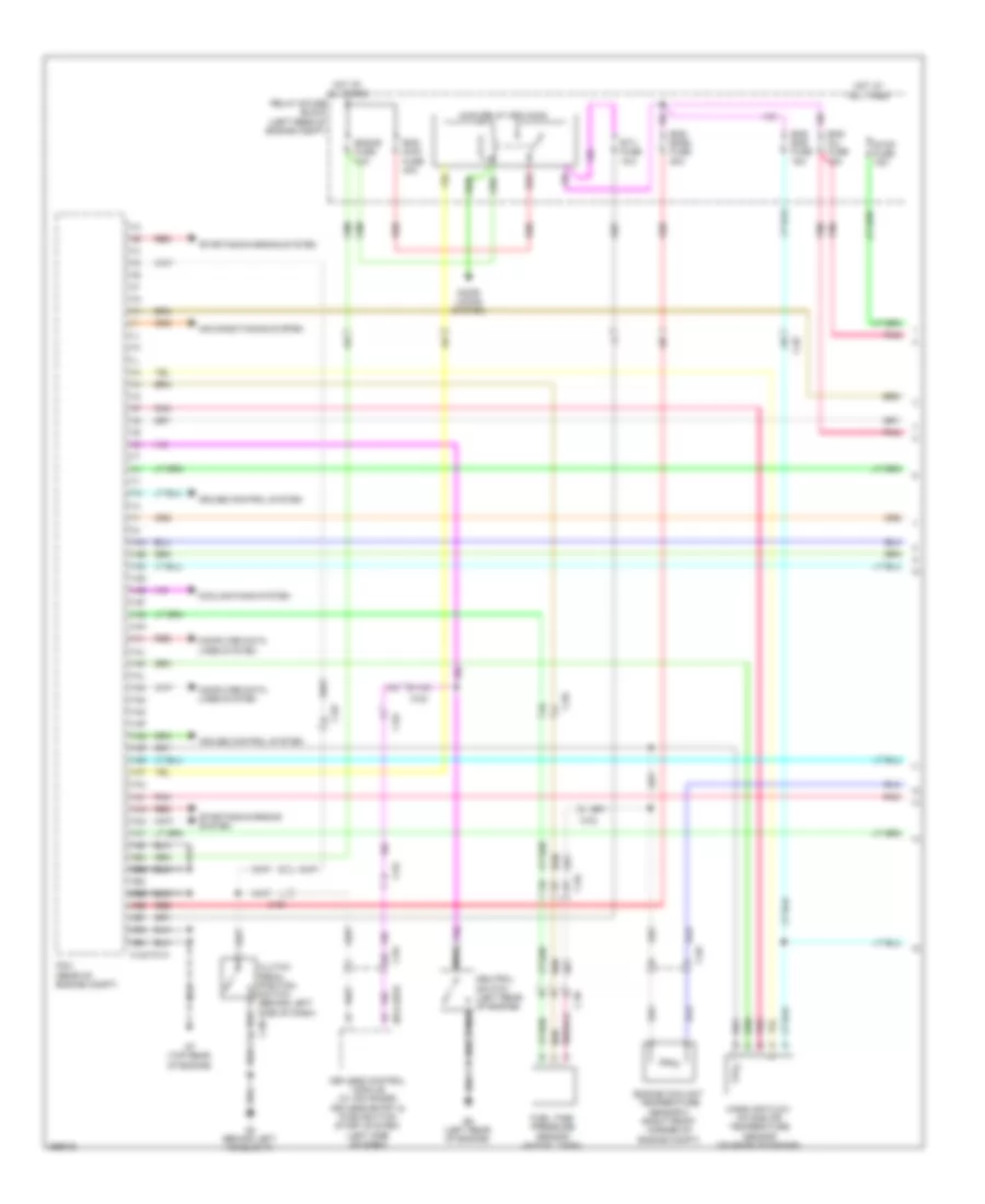
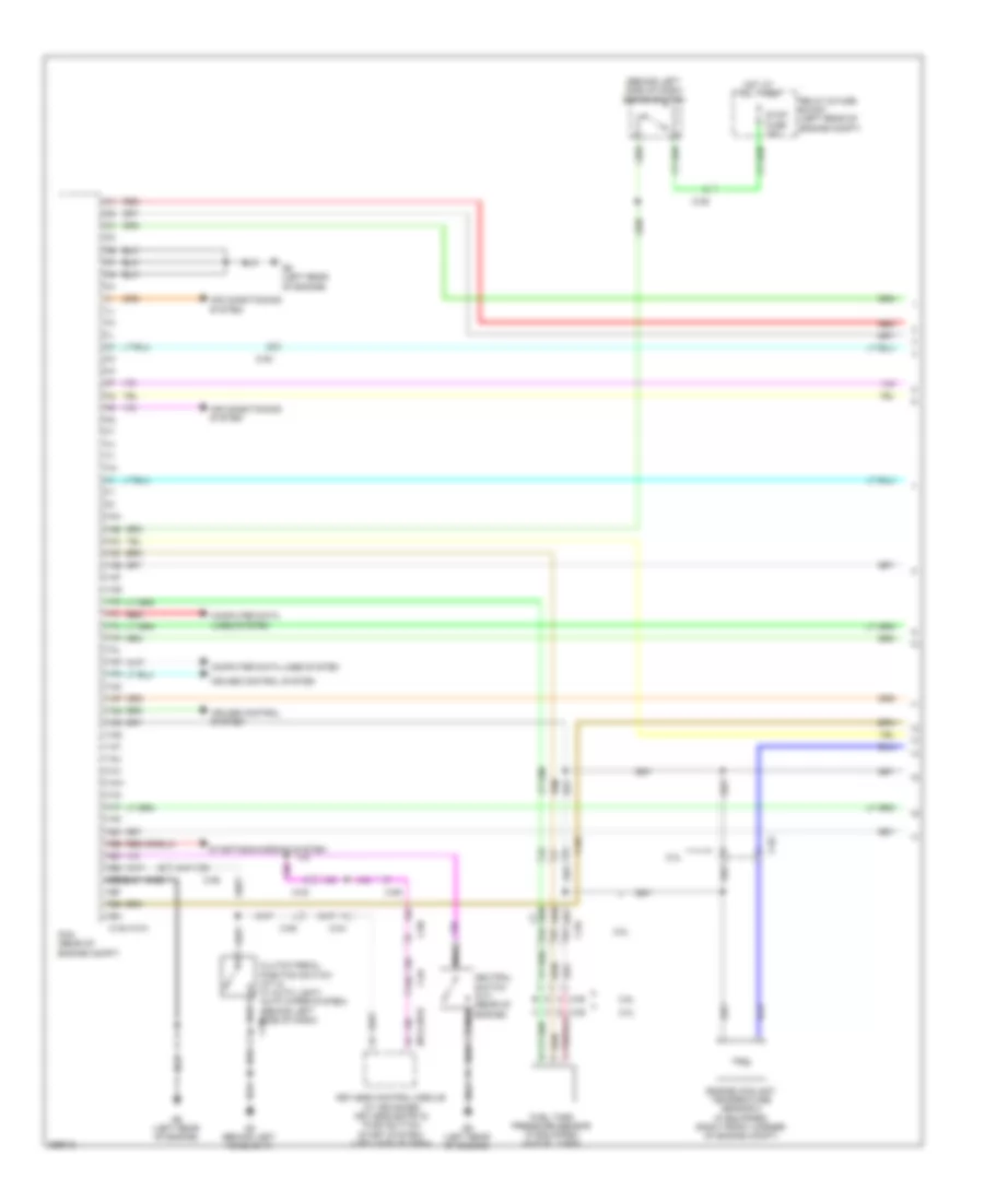
2.0L, Engine Performance Wiring Diagram (1 of 4) for Mazda 3 i Touring 2011

List of elements for 2.0L, Engine Performance Wiring Diagram (1 of 4) for Mazda 3 i Touring 2011:
- (behind left side of dash) brake switch
- 0140-101a
- 0914-201d
- 1aa
- 1ab
- 1ac
- 1ad
- 1ae
- 1af
- 1ag
- 1ah
- 1ai
- 1aj
- 1ak
- 1al
- 1am
- 1an
- 1ao
- 1ap
- 1aq
- 1ar
- 1as
- 1at
- 1au
- 1av
- 1aw
- 1ax
- 1ay
- 1az
- 1ba
- 1bb
- 1bc
- 1bd
- 1be
- 1bf
- 1bg
- 1bh
- 2.0l
- 2.5l
- A c-36
- Air conditioning system
- C-02
- C-04
- C-06
- Clutch pedal position switch (m/t & w/ auto light/ auto wiper system) (behind left side of dash)
- Computer data lines system
- Cruise control system
- Engine coolant temperature sensor 2 (if equipped) (right front corner of engine compt)
- Fuel tank pressure sensor (if equipped) (in fuel tank)
- G c-36
- G2 (behind left headlight)
- G6 (left rear of engine)
- Hot at all times
- Keyless control module (w/ advanced keyless entry & push button start system) (left side of dash)
- Nca
- Neutral switch (m/t) (rear of engine)
- Pcm (rear of engine compt)
- Red
- Relay & fuse block (left rear of engine compt)
- Starting/charging system
- Stop fuse 15a
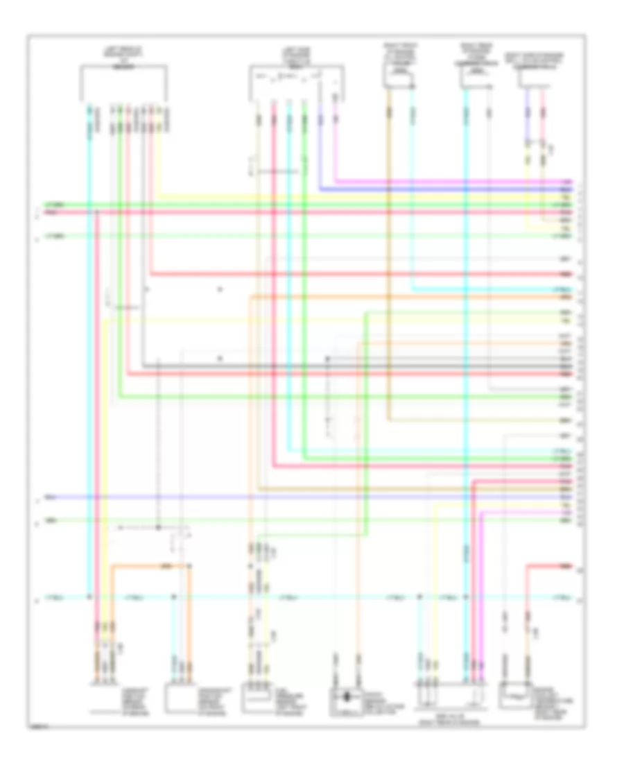
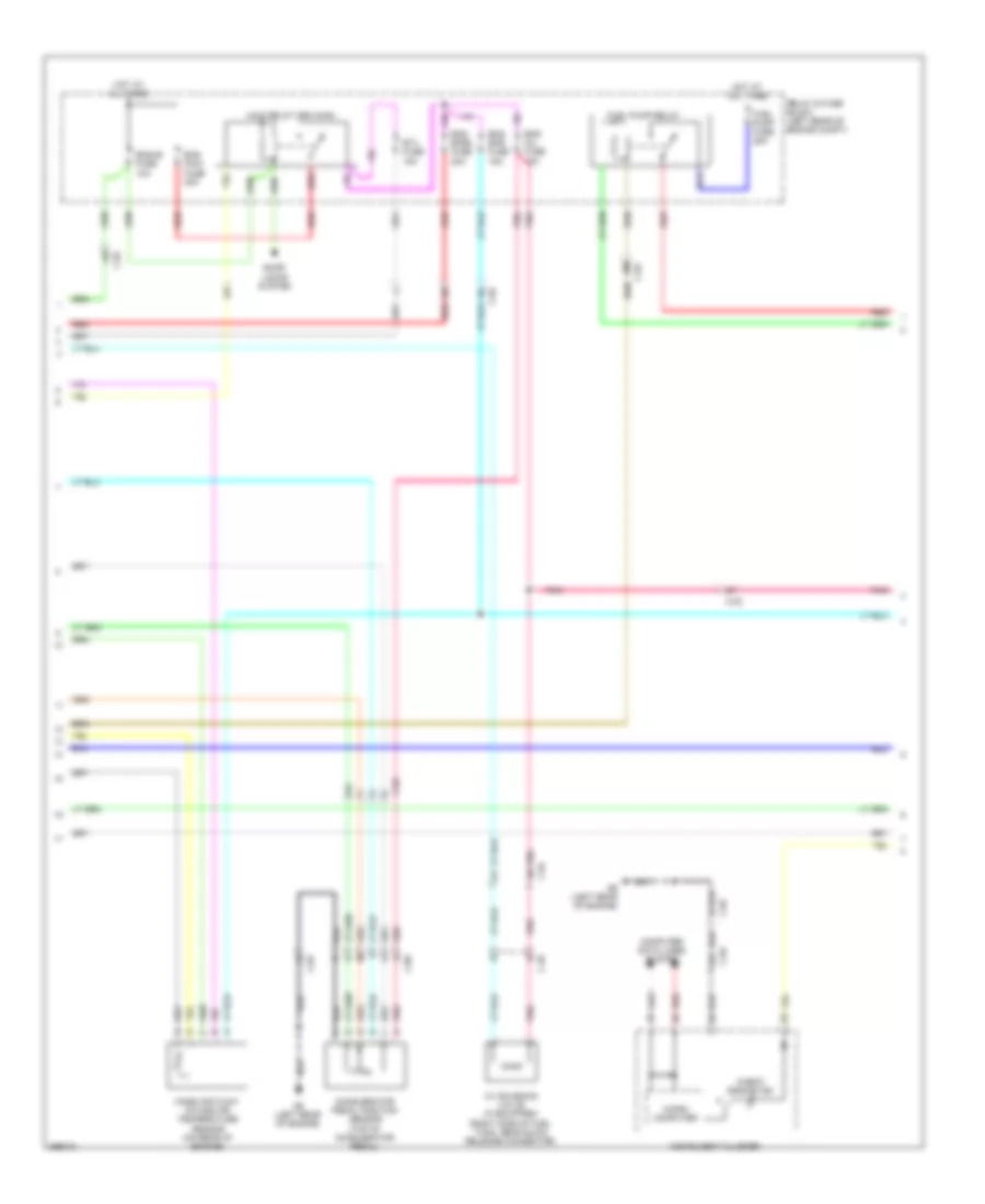
2.0L, Engine Performance Wiring Diagram (2 of 4) for Mazda 3 i Touring 2011
List of elements for 2.0L, Engine Performance Wiring Diagram (2 of 4) for Mazda 3 i Touring 2011:
- Accelerator pedal position sensor (top of accelerator pedal)
- C-02
- C-03
- C-04
- C-06
- C-36
- Check engine ind
- Computer data lines system
- Cv solenoid valve (if equipped) (right side of fuel tank, near quick release connector)
- Door locks system
- Eng bar fuse 15a
- Eng bar2 fuse 20a
- Eng inj fuse 15a
- Eng main fuse 40a
- Eng+b fuse 10a
- Etv fuse 15a
- Fuel pump fuse 25a
- Fuel pump relay
- G6 (left rear of engine)
- Hot at all times
- Instrument cluster
- Main relay (egi main)
- Mass air flow/ intake air temperature sensor (on rear of engine)
- Micro- computer
- Pnk
- Red
- Relay & fuse block (left rear of engine compt)
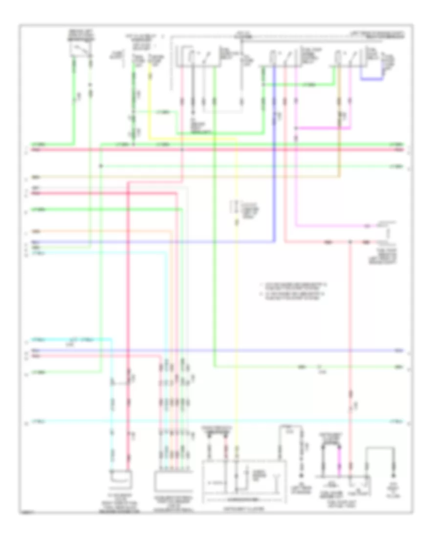
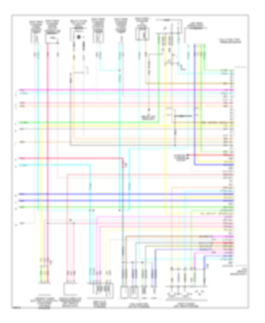
2.0L, Engine Performance Wiring Diagram (3 of 4) for Mazda 3 i Touring 2011
List of elements for 2.0L, Engine Performance Wiring Diagram (3 of 4) for Mazda 3 i Touring 2011:
- (2.5l) c-10
- (left rear of engine) g6
- (on top of engine)
- C-02
- C-03
- C-04
- C-08
- Camshaft position sensor (on rear of engine)
- Crankshaft position sensor (on front of engine)
- Eng fuse 20a
- Fuel gauge sender unit
- Fuel pump
- Fuel pump unit (on fuel tank)
- Fuse block
- G15 (right "c" pillar)
- G6 (left rear of engine)
- Hall ic
- Hot in on or start
- Hot w/ ig/relay energized
- Igniter
- Ignition coil 1
- Ignition coil 2
- Ignition coil 3
- Ignition coil 4
- Instrument cluster system
- J/c c-47 (center left of dash)
- Meter fuse 15a
- Pnk
- Red
- W/ advanced keyless entry & push button start system
- W/ fuel tank pressure sensor
- W/o advanced keyless entry & push button start system
- W/o fuel tank pressure sensor
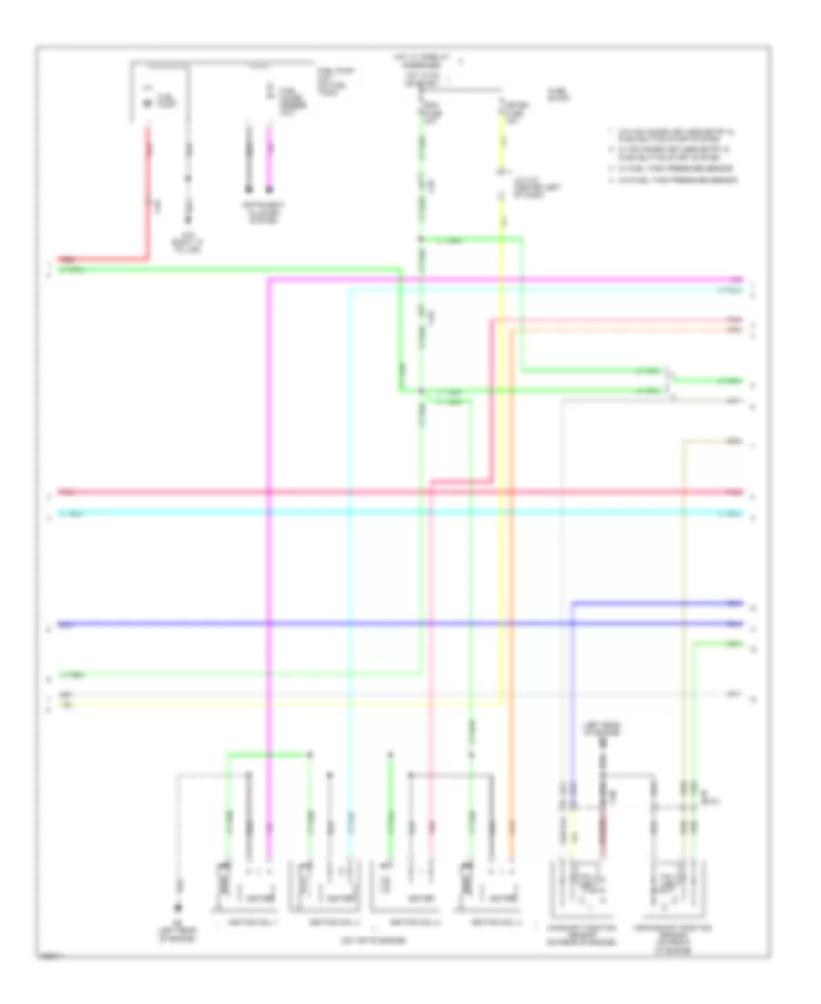
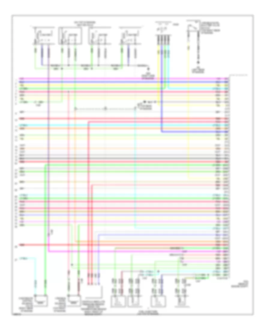
2.0L, Engine Performance Wiring Diagram (4 of 4) for Mazda 3 i Touring 2011
List of elements for 2.0L, Engine Performance Wiring Diagram (4 of 4) for Mazda 3 i Touring 2011:
- (2.5l)
- (below intake collector) knock sensor
- (left rear engine compt) a/f sensor
- (right front of engine) oil control valve
- (right rear of engine) engine coolant temperature sensor 1
- (right rear of engine) purge solenoid valve
- (right rear of engine) variable intake air solenoid valve
- (right rear of engine) variable tumble solenoid valve
- 0140-101b
- 2.5l w/ fuel tank pressure sensor
- 2aa
- 2ab
- 2ac
- 2ad
- 2ae
- 2af
- 2ag
- 2ah
- 2ai
- 2aj
- 2ak
- 2al
- 2am
- 2an
- 2ao
- 2ap
- 2aq
- 2ar
- 2as
- 2at
- 2au
- 2av
- 2aw
- 2ax
- 2ay
- 2az
- 2ba
- 2bb
- 2bc
- 2bd
- 2be
- 2bf
- 2bg
- 2bh
- C-02
- C-08
- C-09
- Egr valve (right rear of engine)
- Fuel injectors (on top of engine)
- G1 (behind left headlight)
- Ho2s
- Manifold absolute pressure sensor (left rear of engine compt)
- Nca
- Pcm (rear of engine compt)
- Pnk
- Red
- Starting/ charging system
- Throttle body (left rear of engine)
- Variable tumble shutter valve switch (if equipped) (top rear of engine)
2.3L TURBO
2.3L Turbo, Engine Performance Wiring Diagram (1 of 4) for Mazda 3 i Touring 2011
List of elements for 2.3L Turbo, Engine Performance Wiring Diagram (1 of 4) for Mazda 3 i Touring 2011:
- 0140-701a
- 0914-201d
- 1aa
- 1ab
- 1ac
- 1ad
- 1ae
- 1af
- 1ag
- 1ah
- 1ai
- 1aj
- 1ak
- 1al
- 1am
- 1an
- 1ao
- 1ap
- 1aq
- 1ar
- 1as
- 1at
- 1au
- 1av
- 1aw
- 1ax
- 1ay
- 1az
- 1ba
- 1bb
- 1bc
- 1bd
- 1be
- 1bf
- 1bg
- 1bh
- Air conditioning system
- C-02
- C-04
- C-06
- C-36
- Clutch pedal position switch (behind left side of dash)
- Computer data lines system
- Cooling fans system
- Cruise control system
- Door locks system
- Eng bar fuse 15a
- Eng bar2 fuse 20a
- Eng inj fuse 15a
- Eng main fuse 40a
- Eng+b fuse 10a
- Engine coolant temperature sensor 2 (right front corner of engine compt)
- Etv fuse 15a
- Fuel tank pressure sensor (in fuel tank)
- G2 (behind left headlight)
- G6 (left rear of engine)
- G7 (top rear of engine)
- Hot at all times
- Keyless control module (w/ advanced keyless entry & push button start system) (left side of dash)
- Main relay (egi main)
- Mass air flow/ intake air temperature sensor (on rear of engine)
- Nca
- Neutral switch (left rear of engine)
- Pcm (rear of engine compt)
- Pnk
- Red
- Relay & fuse block (left rear of engine compt)
- Starting/charging system
- Stop fuse 15a
2.3L Turbo, Engine Performance Wiring Diagram (2 of 4) for Mazda 3 i Touring 2011
List of elements for 2.3L Turbo, Engine Performance Wiring Diagram (2 of 4) for Mazda 3 i Touring 2011:
- (behind left side of dash) brake switch
- (left rear of engine compt) relay & fuse block
- Accelerator pedal position sensor (top of accelerator pedal)
- C-02
- C-03
- C-04
- C-06
- C-36
- Check engine ind
- Computer data lines system
- Cv solenoid valve (right side of fuel tank, near quick release connector)
- Eng fuse 20a
- Fuel gauge sender unit
- Fuel injector relay
- Fuel pump
- Fuel pump relay
- Fuel pump resistor (left front of engine compt)
- Fuel pump speed control relay
- Fuel pump unit (on fuel tank)
- Fuse block
- G15 (right "c" pillar)
- G3 (behind right headlight)
- G6 (left rear of engine)
- Hot at all times
- Hot in on or start
- Hot w/ ig/ relay energized
- Inj fuse 30a
- Instrument cluster
- Instrument cluster system
- J/c c-47 (center left of dash)
- Meter fuse 15a
- Microcomputer
- Pnk
- Red
- W/ advanced keyless entry & push button start system
- W/o advanced keyless entry & push button start system
2.3L Turbo, Engine Performance Wiring Diagram (3 of 4) for Mazda 3 i Touring 2011
List of elements for 2.3L Turbo, Engine Performance Wiring Diagram (3 of 4) for Mazda 3 i Touring 2011:
- (left rear of engine compt)
- (left side of engine) throttle body
- (right front of engine) oil control valve
- (right rear of engine)
- (right side of engine) spill valve control solenoid valve
- 0140-707a
- 0140-707b
- A/f sensor
- C-67
- C-68
- C-69
- Camshaft position sensor (on rear of engine)
- Crankshaft position sensor (on front of engine)
- Egr valve (right rear of engine)
- Engine coolant temperature sensor 1 (right rear of engine)
- Fuel pressure sensor (left front of engine)
- Knock sensor (below intake collector)
- Nca
- Pnk
- Purge solenoid valve
- Red
2.3L Turbo, Engine Performance Wiring Diagram (4 of 4) for Mazda 3 i Touring 2011
List of elements for 2.3L Turbo, Engine Performance Wiring Diagram (4 of 4) for Mazda 3 i Touring 2011:
- (on top of engine) ignition coils
- 0140-701b
- 2aa
- 2ab
- 2ac
- 2ad
- 2ae
- 2af
- 2ag
- 2ah
- 2ai
- 2aj
- 2ak
- 2al
- 2am
- 2an
- 2ao
- 2ap
- 2aq
- 2ar
- 2as
- 2at
- 2au
- 2av
- 2aw
- 2ax
- 2ay
- 2az
- 2ba
- 2bb
- 2bc
- 2bd
- 2be
- 2bf
- 2bg
- 2bh
- C-67
- C-68
- C-69
- Fuel injectors (on top of engine)
- G29 (right side of engine)
- G6 (left rear of engine)
- G7 (top rear of engine) c-68
- Ho2s
- Igniter
- Manifold absolute pressure sensor/ boost air temperature sensor (right front of engine compt)
- Nca
- Pcm (rear of engine compt)
- Pnk
- Red
- Variable swirl shutter valve switch (top right rear of engine)
- Variable swirl solenoid valve (top front of engine)
- Wastegate control solenoid valve (right rear of engine)
2.5L
2.5L, Engine Performance Wiring Diagram (1 of 4) for Mazda 3 i Touring 2011
List of elements for 2.5L, Engine Performance Wiring Diagram (1 of 4) for Mazda 3 i Touring 2011:
- (behind left side of dash) brake switch
- 0140-101a
- 0914-201d
- 1aa
- 1ab
- 1ac
- 1ad
- 1ae
- 1af
- 1ag
- 1ah
- 1ai
- 1aj
- 1ak
- 1al
- 1am
- 1an
- 1ao
- 1ap
- 1aq
- 1ar
- 1as
- 1at
- 1au
- 1av
- 1aw
- 1ax
- 1ay
- 1az
- 1ba
- 1bb
- 1bc
- 1bd
- 1be
- 1bf
- 1bg
- 1bh
- 2.0l
- 2.5l
- A c-36
- Air conditioning system
- C-02
- C-04
- C-06
- Clutch pedal position switch (m/t & w/ auto light/ auto wiper system) (behind left side of dash)
- Computer data lines system
- Cruise control system
- Engine coolant temperature sensor 2 (if equipped) (right front corner of engine compt)
- Fuel tank pressure sensor (if equipped) (in fuel tank)
- G c-36
- G2 (behind left headlight)
- G6 (left rear of engine)
- Hot at all times
- Keyless control module (w/ advanced keyless entry & push button start system) (left side of dash)
- Nca
- Neutral switch (m/t) (rear of engine)
- Pcm (rear of engine compt)
- Red
- Relay & fuse block (left rear of engine compt)
- Starting/charging system
- Stop fuse 15a
2.5L, Engine Performance Wiring Diagram (2 of 4) for Mazda 3 i Touring 2011
List of elements for 2.5L, Engine Performance Wiring Diagram (2 of 4) for Mazda 3 i Touring 2011:
- Accelerator pedal position sensor (top of accelerator pedal)
- C-02
- C-03
- C-04
- C-06
- C-36
- Check engine ind
- Computer data lines system
- Cv solenoid valve (if equipped) (right side of fuel tank, near quick release connector)
- Door locks system
- Eng bar fuse 15a
- Eng bar2 fuse 20a
- Eng inj fuse 15a
- Eng main fuse 40a
- Eng+b fuse 10a
- Etv fuse 15a
- Fuel pump fuse 25a
- Fuel pump relay
- G6 (left rear of engine)
- Hot at all times
- Instrument cluster
- Main relay (egi main)
- Mass air flow/ intake air temperature sensor (on rear of engine)
- Micro- computer
- Pnk
- Red
- Relay & fuse block (left rear of engine compt)
2.5L, Engine Performance Wiring Diagram (3 of 4) for Mazda 3 i Touring 2011
List of elements for 2.5L, Engine Performance Wiring Diagram (3 of 4) for Mazda 3 i Touring 2011:
- (2.5l) c-10
- (left rear of engine) g6
- (on top of engine)
- C-02
- C-03
- C-04
- C-08
- Camshaft position sensor (on rear of engine)
- Crankshaft position sensor (on front of engine)
- Eng fuse 20a
- Fuel gauge sender unit
- Fuel pump
- Fuel pump unit (on fuel tank)
- Fuse block
- G15 (right "c" pillar)
- G6 (left rear of engine)
- Hall ic
- Hot in on or start
- Hot w/ ig/relay energized
- Igniter
- Ignition coil 1
- Ignition coil 2
- Ignition coil 3
- Ignition coil 4
- Instrument cluster system
- J/c c-47 (center left of dash)
- Meter fuse 15a
- Pnk
- Red
- W/ advanced keyless entry & push button start system
- W/ fuel tank pressure sensor
- W/o advanced keyless entry & push button start system
- W/o fuel tank pressure sensor
2.5L, Engine Performance Wiring Diagram (4 of 4) for Mazda 3 i Touring 2011
List of elements for 2.5L, Engine Performance Wiring Diagram (4 of 4) for Mazda 3 i Touring 2011:
- (2.5l)
- (below intake collector) knock sensor
- (left rear engine compt) a/f sensor
- (right front of engine) oil control valve
- (right rear of engine) engine coolant temperature sensor 1
- (right rear of engine) purge solenoid valve
- (right rear of engine) variable intake air solenoid valve
- (right rear of engine) variable tumble solenoid valve
- 0140-101b
- 2.5l w/ fuel tank pressure sensor
- 2aa
- 2ab
- 2ac
- 2ad
- 2ae
- 2af
- 2ag
- 2ah
- 2ai
- 2aj
- 2ak
- 2al
- 2am
- 2an
- 2ao
- 2ap
- 2aq
- 2ar
- 2as
- 2at
- 2au
- 2av
- 2aw
- 2ax
- 2ay
- 2az
- 2ba
- 2bb
- 2bc
- 2bd
- 2be
- 2bf
- 2bg
- 2bh
- C-02
- C-08
- C-09
- Egr valve (right rear of engine)
- Fuel injectors (on top of engine)
- G1 (behind left headlight)
- Ho2s
- Manifold absolute pressure sensor (left rear of engine compt)
- Nca
- Pcm (rear of engine compt)
- Pnk
- Red
- Starting/ charging system
- Throttle body (left rear of engine)
- Variable tumble shutter valve switch (if equipped) (top rear of engine)