ENGINE PERFORMANCE
2.0L SKYACTIV
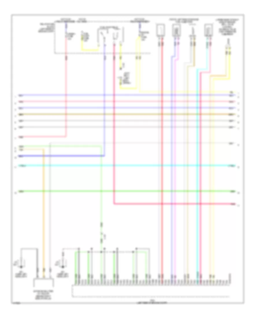
2.0L SKYACTIV, Engine Performance Wiring Diagram (1 of 5) for Mazda 3 Touring 2014

List of elements for 2.0L SKYACTIV, Engine Performance Wiring Diagram (1 of 5) for Mazda 3 Touring 2014:
- (center left side of engine) knock sensor
- (center of left side of engine) crankshaft position sensor
- (front left of top of engine) a/f sensor
- (left rear of cylinder head) intake camshaft position sensor
- (on top of engine)
- (right rear of cylinder head) exhaust camshaft position sensor
- 0140-101a
- 0940-101b
- 1aa
- 1ab
- 1ac
- 1ad
- 1ae
- 1af
- 1ag
- 1ah
- 1ai
- 1aj
- 1ak
- 1al
- 1am
- 1an
- 1ao
- 1ap
- 1aq
- 1ar
- 1as
- 1at
- 1au
- 1av
- 1aw
- 1ax
- 1ay
- 1az
- 1ba
- 1bb
- 1bc
- 1bd
- 1be
- 1bf
- 1bg
- 1bh
- C-01
- Computer data lines system
- Engine coolant temperature sensor 1 (right rear of engine)
- Exterior lights system
- Fbcm (left rear corner of engine compt)
- G08 (left rear of engine)
- Ic igniter ion sensor
- Ignition coil 1
- Ignition coil 2
- Ignition coil 3
- Ignition coil 4
- Nca
- Pcm (left rear of engine compt)
- Pnk
- Red
- Starting/charging system
- Tan
2.0L SKYACTIV, Engine Performance Wiring Diagram (2 of 5) for Mazda 3 Touring 2014
List of elements for 2.0L SKYACTIV, Engine Performance Wiring Diagram (2 of 5) for Mazda 3 Touring 2014:
- (left rear of engine compt) (w/ i-eloop) current sensor
- (left side of engine) throttle body
- (on transaxle) (m/t) neutral switch
- (right front of engine) oil control valve
- (top left side of engine) engine oil solenoid valve
- (upper right rear of engine) purge solenoid valve
- 0140-101a
- 1bi
- 1bj
- 1bk
- 1bl
- 1bm
- 1bn
- 1bo
- 1bp
- 1bq
- 1br
- 1bs
- 1bt
- 1bu
- 1bv
- 1bw
- 1bx
- 1by
- 1bz
- 1ca
- 1cb
- 1cc
- 1cd
- 1ce
- 1cf
- 1cg
- 1ch
- 1ci
- 1cj
- 1ck
- 1cl
- 1cm
- 1cn
- C-52
- Fuel pressure sensor (left front of engine)
- G01 (near left headlight)
- G08 (left rear of engine)
- J/c g01
- Joint box 1 (left kick c-52 panel)
- Manifold absolute pressure sensor/ intake air temperature sensor 2 (intake manifold)
- Oil pressure switch (center of left side of engine)
- Pcm (left rear of engine compt)
- Pnk
- Red
- Starting/charging system
- Tan
2.0L SKYACTIV, Engine Performance Wiring Diagram (3 of 5) for Mazda 3 Touring 2014
List of elements for 2.0L SKYACTIV, Engine Performance Wiring Diagram (3 of 5) for Mazda 3 Touring 2014:
- 0114-102a
- 0114-102b
- 0140-119a
- 0140-119b
- C-01
- C-05
- C-52
- C-54
- Check engine ind
- Computer data lines system
- Cooling fans system
- Electric variable valve timing motor/driver (top front of engine)
- Electric variable valve timing relay (evvt)
- Eng main fuse 40a
- Eng+b fuse 7.5a
- Engine1 fuse 15a
- Engine2 fuse 15a
- Engine3 fuse 15a
- Evvt fuse 20a
- Fuel gauge sender unit
- Fuel injector relay (inj)
- Fuel pump
- Fuel pump control module (under right rear seat)
- Fuel pump unit (on fuel tank)
- G01 (near left headlight)
- G08 (left rear of engine)
- G10 (behind left side of dash)
- G18 (left "c" pillar)
- Hot at all times
- Injector fuse 30a
- Instrument cluster
- Instrument cluster system
- J/c g01
- J/c g10
- Joint box 1 (left kick panel)
- Main relay (eng main)
- Micro- computer
- Pnk
- Red
- Relay & fuse block (left rear of engine compt)
- Tan
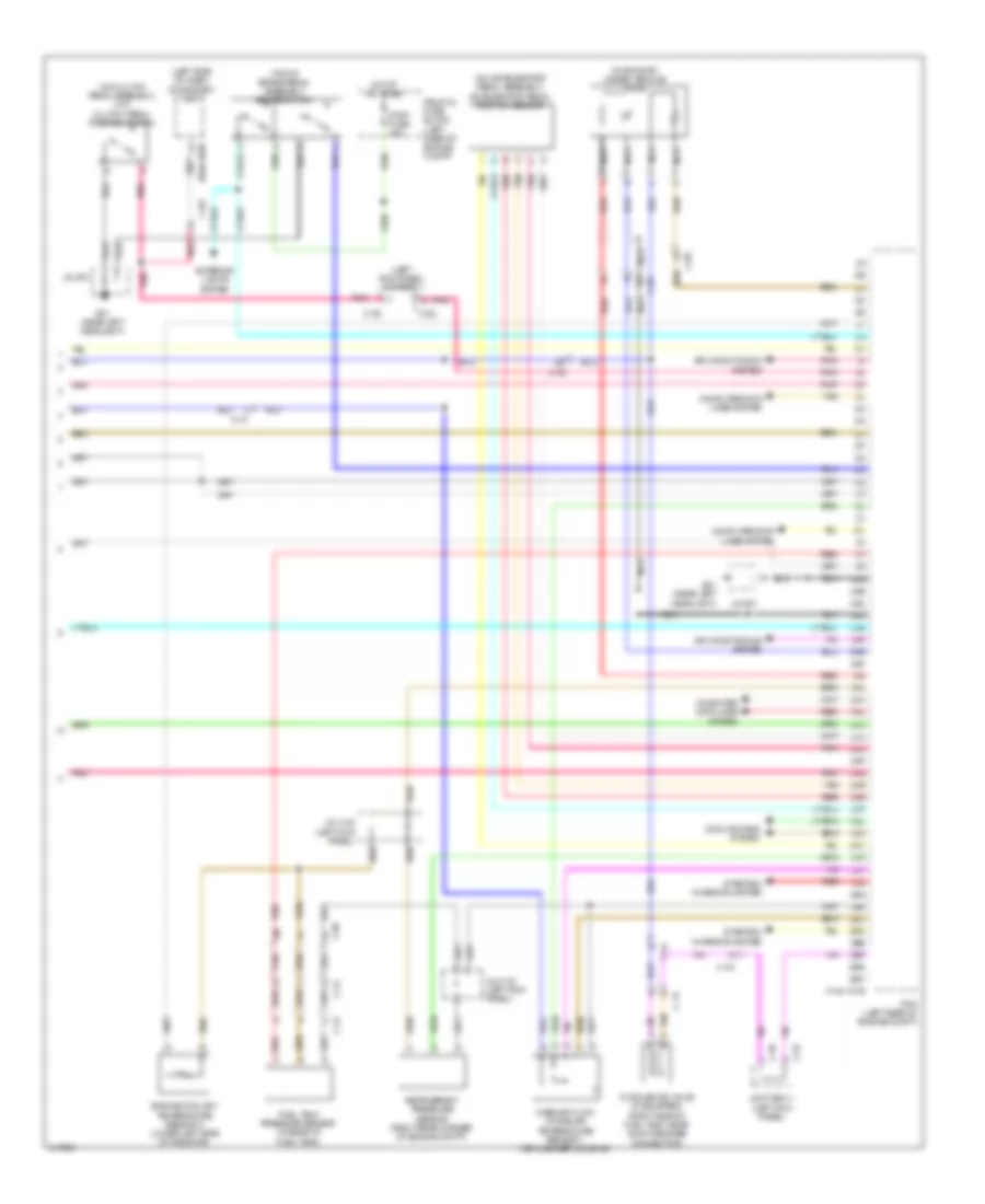
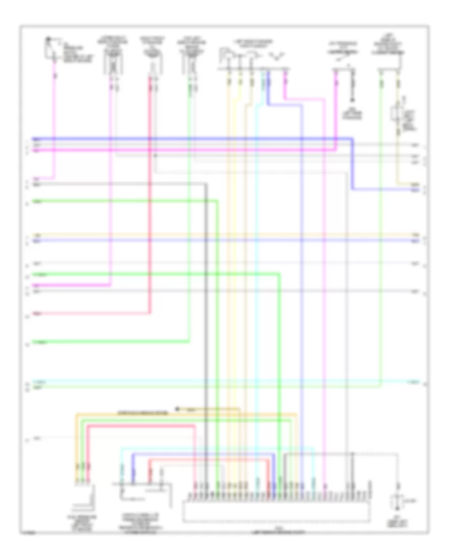
2.0L SKYACTIV, Engine Performance Wiring Diagram (4 of 5) for Mazda 3 Touring 2014
List of elements for 2.0L SKYACTIV, Engine Performance Wiring Diagram (4 of 5) for Mazda 3 Touring 2014:
- (top of left side of engine) fuel injectors
- (upper rear of right side of engine) spill valve control solenoid valve (high pressure fuel pump)
- 0140-101a
- 1co
- 1cp
- 1cq
- 1cr
- 1cs
- 1ct
- 1cu
- 1cv
- 1cw
- 1cx
- 1cy
- 1cz
- 1da
- 1db
- 1dc
- 1dd
- 1de
- 1df
- 1dg
- 1dh
- 1di
- 1dj
- 1dk
- 1dl
- 1dm
- 1dn
- 1do
- 1dp
- 1dq
- 1dr
- 1ds
- 1dt
- 1du
- 1dv
- 1dw
- 1dx
- 1dy
- 1dz
- 1ea
- 1eb
- 1ec
- 1ed
- 1ee
- 1ef
- 1eg
- 1eh
- 1ei
- 1ej
- A tan
- Active air shutter (w/ i-eloop) (behind right side of grille)
- B pnk
- B red
- C-01
- C-52
- Engine ig1 fuse 15a
- Fuel pump fuse 15a
- Fuel pump relay
- G01 (near left headlight)
- Hot at all times
- Hot w/ ig1 relay energized
- J/c g01
- Joint box 1 (left kick c-51
- Meter 1 fuse 10a
- Panel)
- Pcm (left rear of engine compt)
- Pnk
- Red
- Relay & fuse block (left rear of engine compt)
- Tan
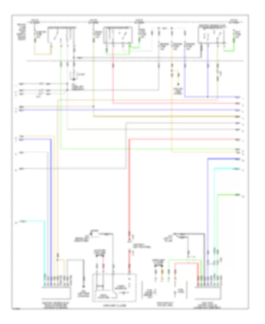
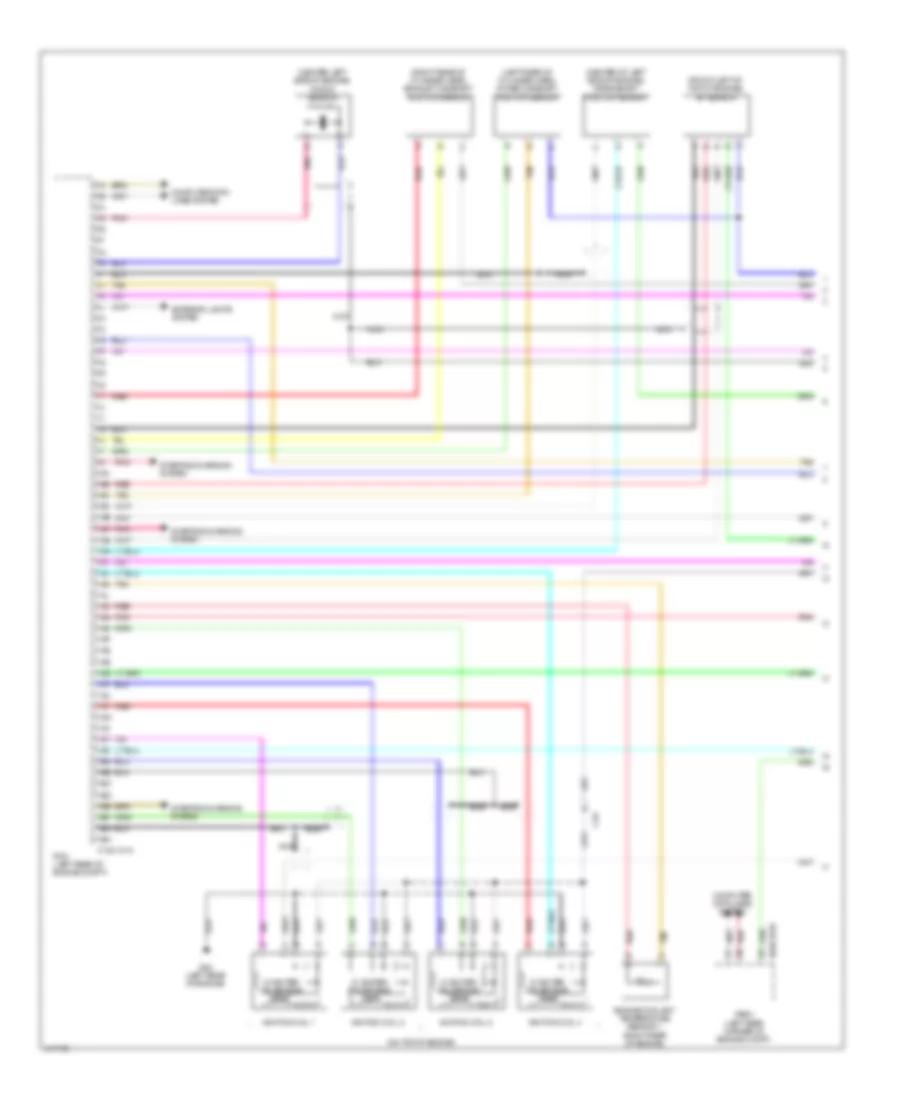
2.0L SKYACTIV, Engine Performance Wiring Diagram (5 of 5) for Mazda 3 Touring 2014
List of elements for 2.0L SKYACTIV, Engine Performance Wiring Diagram (5 of 5) for Mazda 3 Touring 2014:
- (in exhaust, under vehicle) ho2s
- (left kick panel) joint box 1
- (left side of dash) stop/start unit
- (on accelerator pedal assembly) accelerator pedal position sensor
- (on clutch pedal assembly) (m/t) clutch pedal position switch
- (top of brake pedal assembly) brake switch
- 0140-101b
- 0940-103b
- 2aa
- 2ab
- 2ac
- 2ad
- 2ae
- 2af
- 2ag
- 2ah
- 2ai
- 2aj
- 2ak
- 2al
- 2am
- 2an
- 2ao
- 2ap
- 2aq
- 2ar
- 2as
- 2at
- 2au
- 2av
- 2aw
- 2ax
- 2ay
- 2az
- 2ba
- 2bb
- 2bc
- 2bd
- 2be
- 2bf
- 2bg
- 2bh
- Air conditioning system
- C-03
- C-05
- C-24
- C-31
- C-52
- C-56
- Computer data lines system
- Cooling fans system
- Cv solenoid valve (if equipped) (right side of fuel tank, near quick release connector)
- Engine coolant temperature sensor 2 (lower left side of radiator)
- Exterior lights system
- Fuel tank pressure sensor (in rear of fuel tank)
- G01 (near left headlight)
- H red
- Hot at all times
- J c-01
- J/c c-32 (left kick panel)
- J/c g01
- Joint box 1 (left kick panel)
- Mass air flow/ intake air temperature sensor 1 (air cleaner housing)
- Nca
- Pcm (left rear of engine compt)
- Pnk
- Red
- Red c
- Refrigerant pressure sensor (right rear corner of engine compt)
- Relay & fuse block (left rear of engine compt)
- Starting/ charging system
- Stop fuse 10a
- Tan
- Tan b
2.5L
2.5L, Engine Performance Wiring Diagram (1 of 5) for Mazda 3 Touring 2014
List of elements for 2.5L, Engine Performance Wiring Diagram (1 of 5) for Mazda 3 Touring 2014:
- (center left side of engine) knock sensor
- (center of left side of engine) crankshaft position sensor
- (front left of top of engine) a/f sensor
- (left rear of cylinder head) intake camshaft position sensor
- (on top of engine)
- (right rear of cylinder head) exhaust camshaft position sensor
- 0140-101a
- 0940-101b
- 1aa
- 1ab
- 1ac
- 1ad
- 1ae
- 1af
- 1ag
- 1ah
- 1ai
- 1aj
- 1ak
- 1al
- 1am
- 1an
- 1ao
- 1ap
- 1aq
- 1ar
- 1as
- 1at
- 1au
- 1av
- 1aw
- 1ax
- 1ay
- 1az
- 1ba
- 1bb
- 1bc
- 1bd
- 1be
- 1bf
- 1bg
- 1bh
- C-01
- Computer data lines system
- Engine coolant temperature sensor 1 (right rear of engine)
- Exterior lights system
- Fbcm (left rear corner of engine compt)
- G08 (left rear of engine)
- Ic igniter ion sensor
- Ignition coil 1
- Ignition coil 2
- Ignition coil 3
- Ignition coil 4
- Nca
- Pcm (left rear of engine compt)
- Pnk
- Red
- Starting/charging system
- Tan
2.5L, Engine Performance Wiring Diagram (2 of 5) for Mazda 3 Touring 2014
List of elements for 2.5L, Engine Performance Wiring Diagram (2 of 5) for Mazda 3 Touring 2014:
- (left rear of engine compt) (w/ i-eloop) current sensor
- (left side of engine) throttle body
- (on transaxle) (m/t) neutral switch
- (right front of engine) oil control valve
- (top left side of engine) engine oil solenoid valve
- (upper right rear of engine) purge solenoid valve
- 0140-101a
- 1bi
- 1bj
- 1bk
- 1bl
- 1bm
- 1bn
- 1bo
- 1bp
- 1bq
- 1br
- 1bs
- 1bt
- 1bu
- 1bv
- 1bw
- 1bx
- 1by
- 1bz
- 1ca
- 1cb
- 1cc
- 1cd
- 1ce
- 1cf
- 1cg
- 1ch
- 1ci
- 1cj
- 1ck
- 1cl
- 1cm
- 1cn
- C-52
- Fuel pressure sensor (left front of engine)
- G01 (near left headlight)
- G08 (left rear of engine)
- J/c g01
- Joint box 1 (left kick c-52 panel)
- Manifold absolute pressure sensor/ intake air temperature sensor 2 (intake manifold)
- Oil pressure switch (center of left side of engine)
- Pcm (left rear of engine compt)
- Pnk
- Red
- Starting/charging system
- Tan
2.5L, Engine Performance Wiring Diagram (3 of 5) for Mazda 3 Touring 2014
List of elements for 2.5L, Engine Performance Wiring Diagram (3 of 5) for Mazda 3 Touring 2014:
- 0114-102a
- 0114-102b
- 0140-119a
- 0140-119b
- C-01
- C-05
- C-52
- C-54
- Check engine ind
- Computer data lines system
- Cooling fans system
- Electric variable valve timing motor/driver (top front of engine)
- Electric variable valve timing relay (evvt)
- Eng main fuse 40a
- Eng+b fuse 7.5a
- Engine1 fuse 15a
- Engine2 fuse 15a
- Engine3 fuse 15a
- Evvt fuse 20a
- Fuel gauge sender unit
- Fuel injector relay (inj)
- Fuel pump
- Fuel pump control module (under right rear seat)
- Fuel pump unit (on fuel tank)
- G01 (near left headlight)
- G08 (left rear of engine)
- G10 (behind left side of dash)
- G18 (left "c" pillar)
- Hot at all times
- Injector fuse 30a
- Instrument cluster
- Instrument cluster system
- J/c g01
- J/c g10
- Joint box 1 (left kick panel)
- Main relay (eng main)
- Micro- computer
- Pnk
- Red
- Relay & fuse block (left rear of engine compt)
- Tan
2.5L, Engine Performance Wiring Diagram (4 of 5) for Mazda 3 Touring 2014
List of elements for 2.5L, Engine Performance Wiring Diagram (4 of 5) for Mazda 3 Touring 2014:
- (top of left side of engine) fuel injectors
- (upper rear of right side of engine) spill valve control solenoid valve (high pressure fuel pump)
- 0140-101a
- 1co
- 1cp
- 1cq
- 1cr
- 1cs
- 1ct
- 1cu
- 1cv
- 1cw
- 1cx
- 1cy
- 1cz
- 1da
- 1db
- 1dc
- 1dd
- 1de
- 1df
- 1dg
- 1dh
- 1di
- 1dj
- 1dk
- 1dl
- 1dm
- 1dn
- 1do
- 1dp
- 1dq
- 1dr
- 1ds
- 1dt
- 1du
- 1dv
- 1dw
- 1dx
- 1dy
- 1dz
- 1ea
- 1eb
- 1ec
- 1ed
- 1ee
- 1ef
- 1eg
- 1eh
- 1ei
- 1ej
- A tan
- Active air shutter (w/ i-eloop) (behind right side of grille)
- B pnk
- B red
- C-01
- C-52
- Engine ig1 fuse 15a
- Fuel pump fuse 15a
- Fuel pump relay
- G01 (near left headlight)
- Hot at all times
- Hot w/ ig1 relay energized
- J/c g01
- Joint box 1 (left kick c-51
- Meter 1 fuse 10a
- Panel)
- Pcm (left rear of engine compt)
- Pnk
- Red
- Relay & fuse block (left rear of engine compt)
- Tan
2.5L, Engine Performance Wiring Diagram (5 of 5) for Mazda 3 Touring 2014
List of elements for 2.5L, Engine Performance Wiring Diagram (5 of 5) for Mazda 3 Touring 2014:
- (in exhaust, under vehicle) ho2s
- (left kick panel) joint box 1
- (left side of dash) stop/start unit
- (on accelerator pedal assembly) accelerator pedal position sensor
- (on clutch pedal assembly) (m/t) clutch pedal position switch
- (top of brake pedal assembly) brake switch
- 0140-101b
- 0940-103b
- 2aa
- 2ab
- 2ac
- 2ad
- 2ae
- 2af
- 2ag
- 2ah
- 2ai
- 2aj
- 2ak
- 2al
- 2am
- 2an
- 2ao
- 2ap
- 2aq
- 2ar
- 2as
- 2at
- 2au
- 2av
- 2aw
- 2ax
- 2ay
- 2az
- 2ba
- 2bb
- 2bc
- 2bd
- 2be
- 2bf
- 2bg
- 2bh
- Air conditioning system
- C-03
- C-05
- C-24
- C-31
- C-52
- C-56
- Computer data lines system
- Cooling fans system
- Cv solenoid valve (if equipped) (right side of fuel tank, near quick release connector)
- Engine coolant temperature sensor 2 (lower left side of radiator)
- Exterior lights system
- Fuel tank pressure sensor (in rear of fuel tank)
- G01 (near left headlight)
- H red
- Hot at all times
- J c-01
- J/c c-32 (left kick panel)
- J/c g01
- Joint box 1 (left kick panel)
- Mass air flow/ intake air temperature sensor 1 (air cleaner housing)
- Nca
- Pcm (left rear of engine compt)
- Pnk
- Red
- Red c
- Refrigerant pressure sensor (right rear corner of engine compt)
- Relay & fuse block (left rear of engine compt)
- Starting/ charging system
- Stop fuse 10a
- Tan
- Tan b