ENGINE PERFORMANCE
2.5L
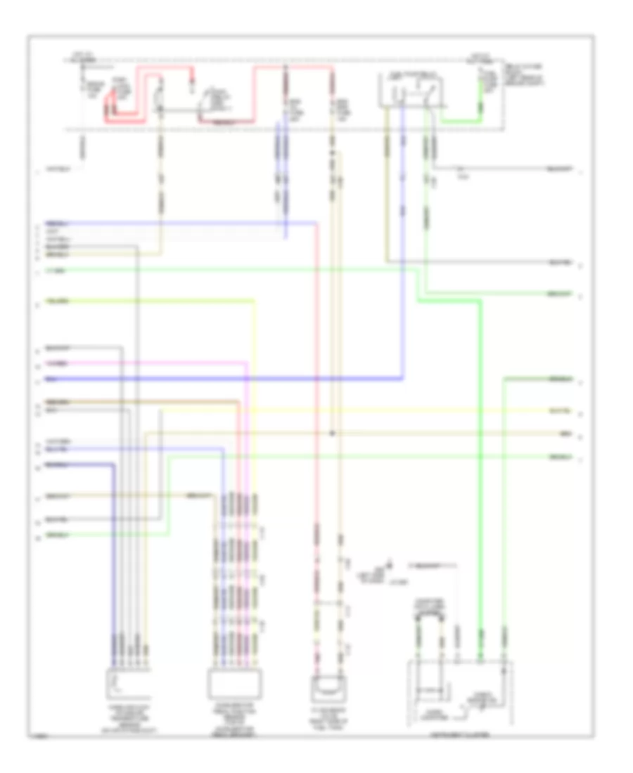
2.5L, Engine Performance Wiring Diagram (1 of 4) for Mazda 5 Grand Touring 2013

List of elements for 2.5L, Engine Performance Wiring Diagram (1 of 4) for Mazda 5 Grand Touring 2013:
- (top of brake pedal bracket) brake switch
- (under passenger's seat) g14
- 0140-101a
- 1aa
- 1ab
- 1ac
- 1ad
- 1ae
- 1af
- 1ag
- 1ah
- 1ai
- 1aj
- 1ak
- 1al
- 1am
- 1an
- 1ao
- 1ap
- 1aq
- 1ar
- 1as
- 1at
- 1au
- 1av
- 1aw
- 1ax
- 1ay
- 1az
- 1ba
- 1bb
- 1bc
- 1bd
- 1be
- 1bf
- 1bg
- 1bh
- Air conditioning system
- C-02
- C-04
- C-10
- C-11
- C-12
- C-18
- Clutch pedal position switch (m/t) (top of clutch pedal bracket)
- Computer data lines system
- Cooling fans system
- Cruise control system
- Exterior lights system
- Fuel tank pressure sensor (near fuel tank, in fuel line)
- G14 (under passenger's seat)
- G23 (left rear of engine)
- Hot at all times
- Nca
- Neutral switch (m/t) (left side of manual transaxle)
- Pcm (left rear of engine compt)
- Pnk
- Power distribution system
- Red
- Relay & fuse block (left rear of engine compt)
- Starting/charging system
- Stop fuse 10a
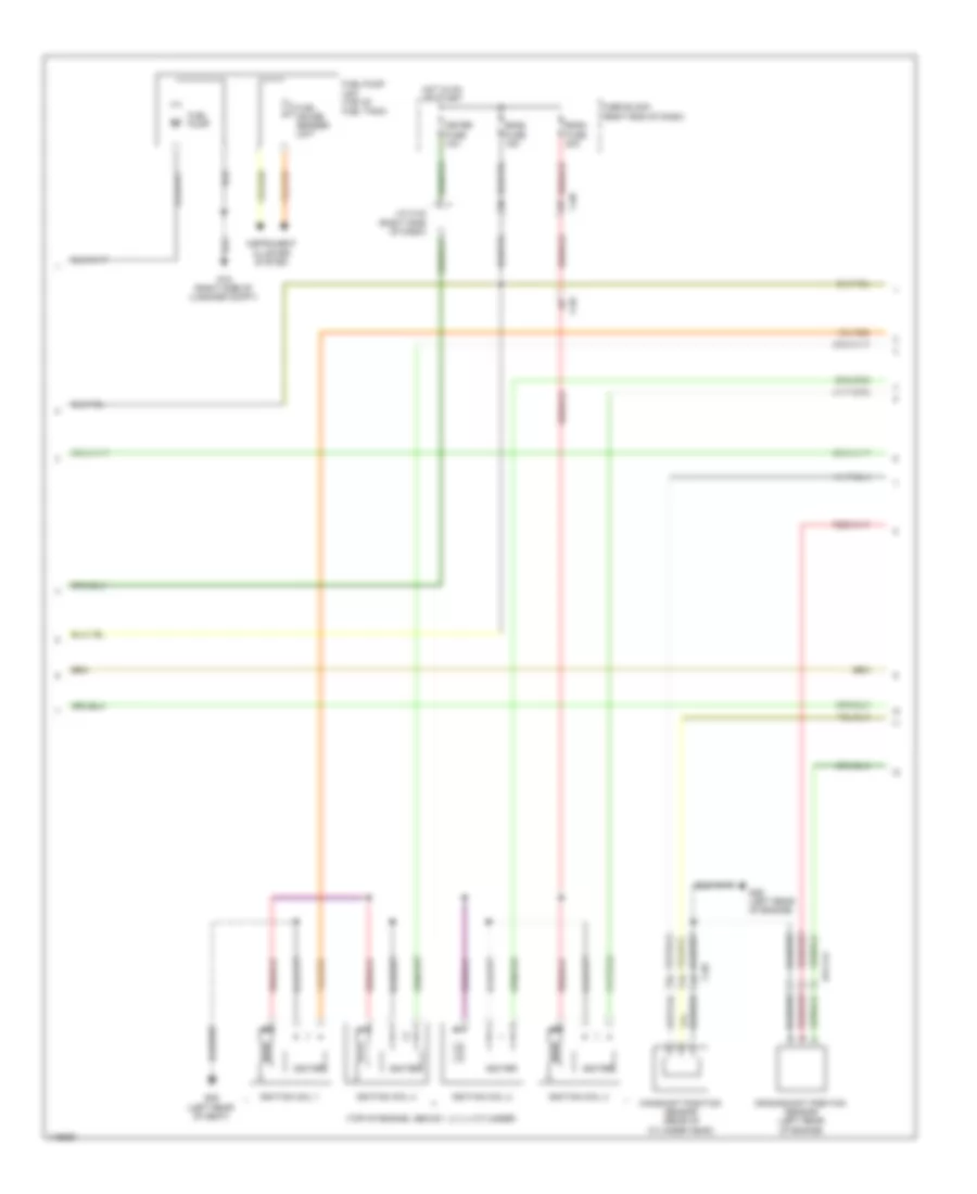
2.5L, Engine Performance Wiring Diagram (2 of 4) for Mazda 5 Grand Touring 2013
List of elements for 2.5L, Engine Performance Wiring Diagram (2 of 4) for Mazda 5 Grand Touring 2013:
- Accelerator pedal position sensor (top of accelerator pedal bracket)
- C-02
- C-04
- C-10
- C-11
- C-12
- C-13
- Check engine ind
- Computer data lines system
- Cv solenoid valve (right side of fuel tank)
- Eg1 main fuse 40a
- Eng bar fuse 15a
- Eng inj fuse 25a
- Eng+b fuse 10a
- Fuel pump fuse 20a
- Fuel pump relay
- G09 (left side of dash)
- Hot at all times
- Instrument cluster
- J/c g09
- Main relay (egi main 1)
- Mass air flow/ intake air temperature sensor (on air intake duct)
- Micro- computer
- Pnk
- Red
- Relay & fuse block (left rear of engine compt)
2.5L, Engine Performance Wiring Diagram (3 of 4) for Mazda 5 Grand Touring 2013
List of elements for 2.5L, Engine Performance Wiring Diagram (3 of 4) for Mazda 5 Grand Touring 2013:
- (top of engine, above 1, 2, 3, 4 cylinder)
- 014-141
- C-02
- C-05
- C-69
- Camshaft position sensor (rear of cylinder head)
- Crankshaft position sensor (left rear of engine)
- Eng2 fuse 15a
- Eng3 fuse 20a
- Fuel gauge sender unit
- Fuel pump
- Fuel pump unit (top of fuel tank)
- Fuse block (right end of dash)
- G15 (right side of luggage compt)
- G29 (left rear of engine)
- G29 (left rear of seat)
- Hot in on or start
- Igniter
- Ignition coil 1
- Ignition coil 2
- Ignition coil 3
- Ignition coil 4
- Instrument cluster system
- J/c c-42 (right side of dash)
- Meter fuse 10a
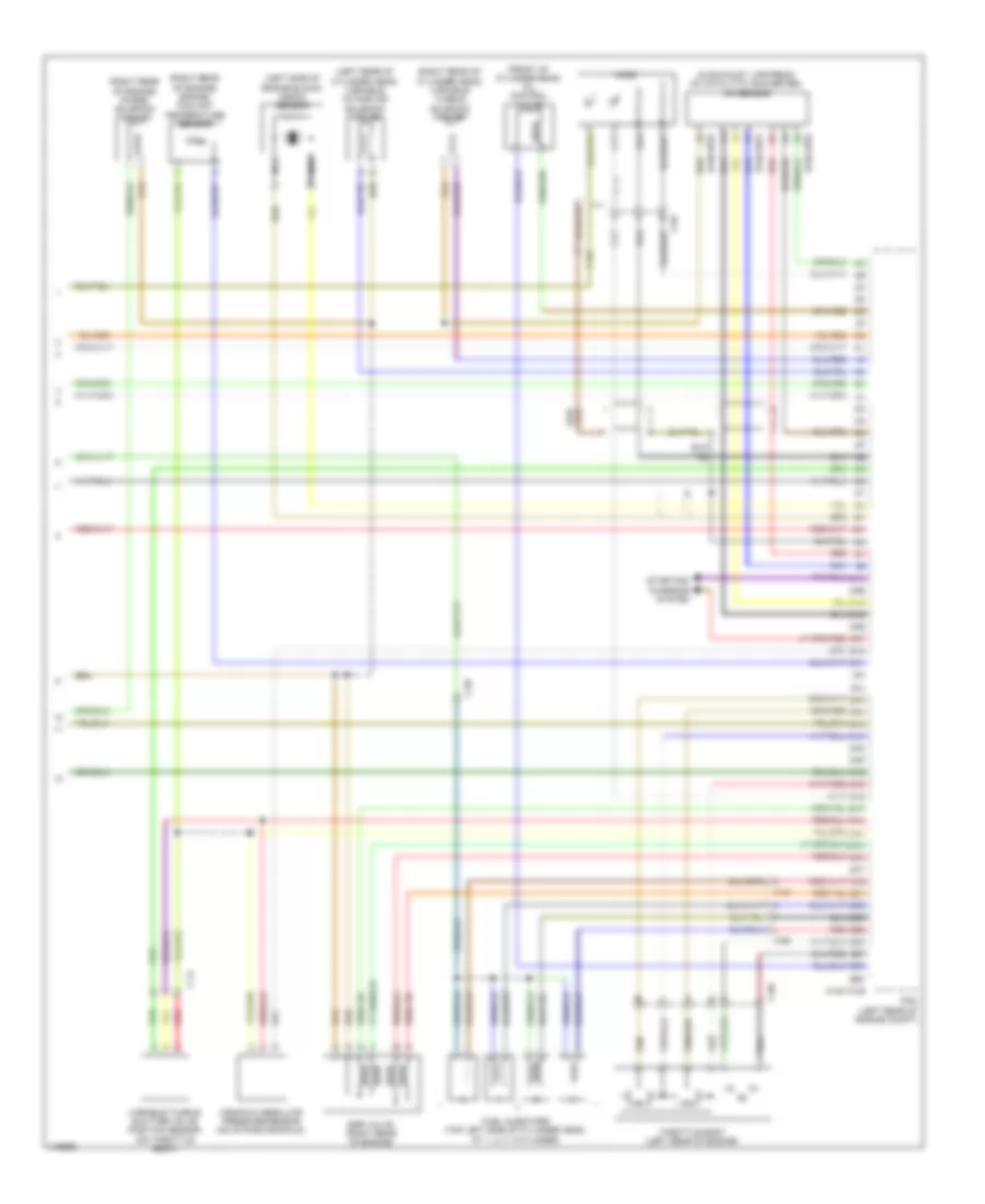
2.5L, Engine Performance Wiring Diagram (4 of 4) for Mazda 5 Grand Touring 2013
List of elements for 2.5L, Engine Performance Wiring Diagram (4 of 4) for Mazda 5 Grand Touring 2013:
- (front of cylinder head) oil control valve
- (in exhaust, upstream of catalytic converter) a/f sensor
- (left rear of cylinder head) variable intake air solenoid valve
- (left side of engine block) knock sensor
- (right rear of cylinder head) variable tumble solenoid valve
- (right rear of engine) engine coolant temperature sensor
- (right rear of engine) purge solenoid valve
- 0140-101b
- 0140-107a
- 0140-107b
- 2aa
- 2ab
- 2ac
- 2ad
- 2ae
- 2af
- 2ag
- 2ah
- 2ai
- 2aj
- 2ak
- 2al
- 2am
- 2an
- 2ao
- 2ap
- 2aq
- 2ar
- 2as
- 2at
- 2au
- 2av
- 2aw
- 2ax
- 2ay
- 2az
- 2ba
- 2bb
- 2bc
- 2bd
- 2be
- 2bf
- 2bg
- 2bh
- C-02
- C-14
- C-69
- Egr valve (right rear of engine)
- Fuel injectors (top left side of cylinder head, at 1, 2, 3, 4 cylinder)
- Ho2s
- Manifold absolute pressure sensor (on intake manifold)
- Nca
- Pcm (left rear of engine compt)
- Red
- Starting/ charging system
- Throttle body (left rear of engine)
- Variable tumble shutter valve position sensor (on throttle body)