ENGINE PERFORMANCE
2.0L
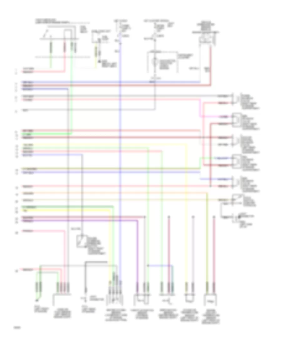
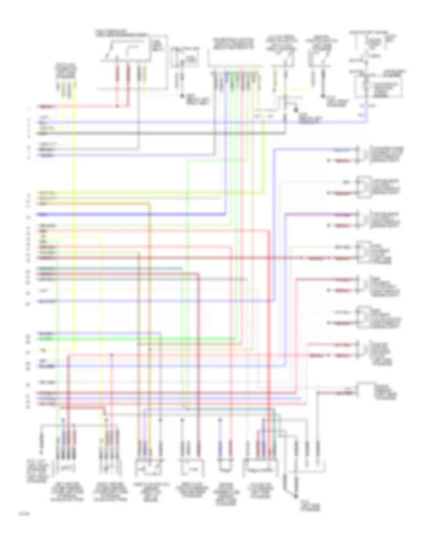
2.0L, Engine Performance Wiring Diagrams, A/T (1 of 2) for Mazda 626 DX 1994

List of elements for 2.0L, Engine Performance Wiring Diagrams, A/T (1 of 2) for Mazda 626 DX 1994:
- A/c relay
- Acc
- Blower switch
- Canada only
- Central processing unit
- Cjb-01
- Cjb-02
- Cjb-03
- Condenser (left side of engine compt)
- Cooling fan relay no. 1
- Cooling fan relay no. 2,3
- Crankshaft position sensor (left front of engine)
- Cruise control unit
- Cruise control unit
- Data link connector (near main fuse block)
- Drl relay
- Egi inj fuse 30a
- Engine fuse 10 15a
- Fuel injectors
- G110 (left front of engine)
- G114 (left rear of engine)
- Headlight relay
- Hot at all times
- Hot in start or run
- Ignition coil (left side of engine compt)
- Ignition control module (left front of engine compartment)
- Ignition switch
- Instrument cluster
- Joint box
- Joint connector
- Lock
- Main fuse block (left side of engine compt)
- Off
- Pcm power relay
- Pnk
- Powertrain control module (left side of safety wall)
- Red
- Refrigerant pressure switch refrigerant pressure switch
- Room fuse 2 15a
- Run
- Self test input terminal
- Solenoid body (left front of engine compartment)
- Spout test connector (left side of engine compartment)
- Start
- Starter interrupt relay
- Stop fuse 1 20a
- Stoplight switch (on brake pedal support)
- Transmission range sensor (lower left of engine compartment)
- Turbine shaft speed sensor (rear of engine compartment)
- Vi0/red
- With theft- deterrent system
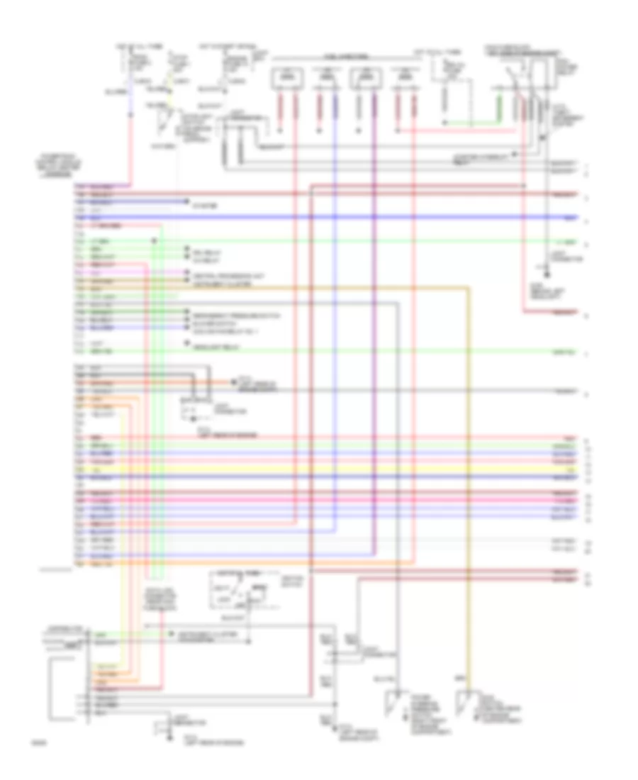
2.0L, Engine Performance Wiring Diagrams, A/T (2 of 2) for Mazda 626 DX 1994
List of elements for 2.0L, Engine Performance Wiring Diagrams, A/T (2 of 2) for Mazda 626 DX 1994:
- C-01
- Cjb-03
- Egr function sensor (center rear of engine compt)
- Egr solenoid valve (right rear of engine compartment)
- Engine coolant temperature sensor (left front of engine compt)
- Fuel pump
- Fuel pump relay
- Fuel tank unit
- G110 (left front of engine)
- G114 (left rear of engine)
- G202 (left side of i/p)
- G300 (below left front seat)
- Heated oxygen sensor (lower right side of engine, on exhaust pipe)
- Hold switch (center console)
- Hot in run
- Hot in start or run
- Idle air control solenoid valve (left rear of engine compartment)
- Instrument cluster
- Intake air temperature sensor (left front of engine compt)
- Joint box
- Joint connector
- Main fuse block (left side of engine compt)
- Malfunction indicator (check engine)
- Mass air flow sensor (left rear of engine compt)
- Meter fuse 8 15a
- Nca
- Power steering pressure switch (right front of engine compartment)
- Prc solenoid valve (right rear of engine compartment)
- Purge solenoid valve (right rear of engine compartment)
- Throttle position sensor (top rear of engine)
- Vehicle speedometer sensor (rear of engine compartment)
- Wiper fuse 13 20a
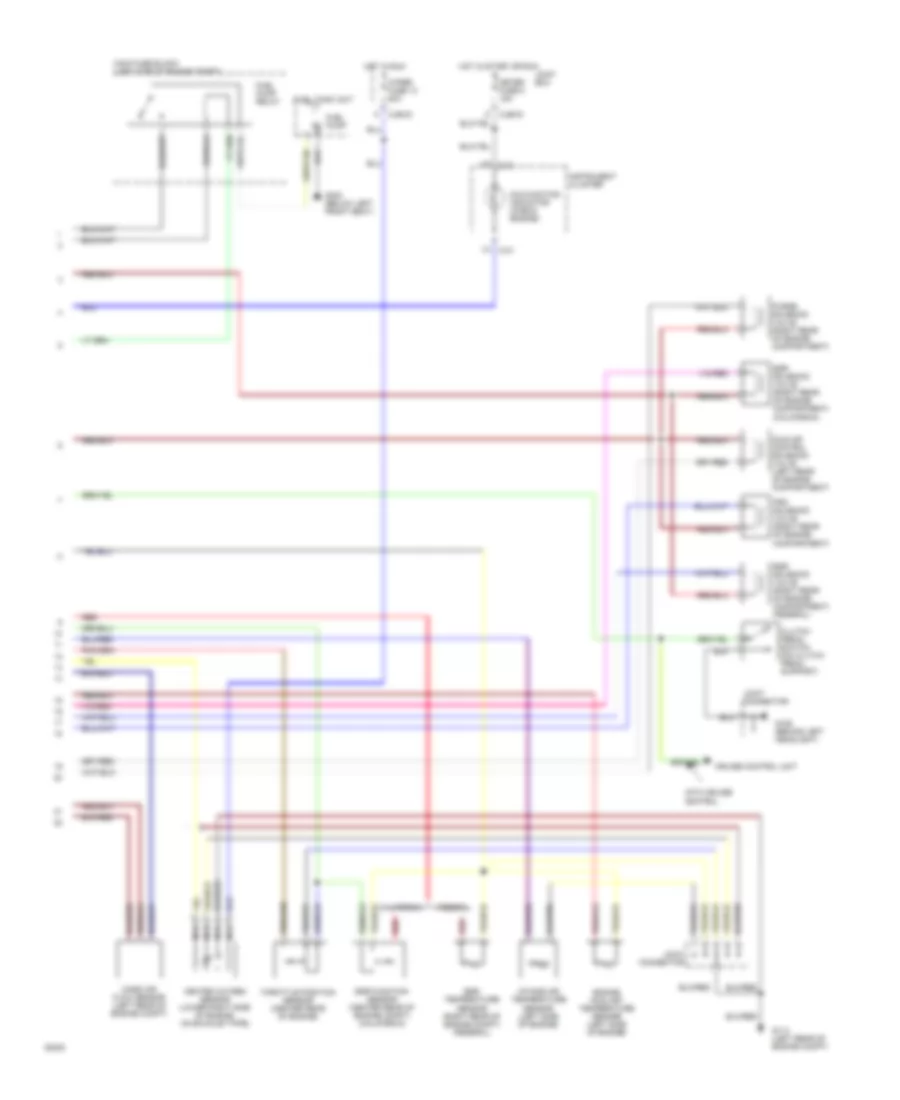
2.0L, Engine Performance Wiring Diagrams, M/T (1 of 2) for Mazda 626 DX 1994
List of elements for 2.0L, Engine Performance Wiring Diagrams, M/T (1 of 2) for Mazda 626 DX 1994:
- A/c relay
- Acc
- Blower switch
- Central processing unit
- Cjb-01
- Cjb-02
- Cjb-03
- Cooling fan relay no. 1
- Data link connector (near main fuse block)
- Distributor
- Drl relay
- Egi inj fuse 30a
- Engine fuse 10 15a
- Fuel injectors
- G106 (behind left headlight)
- G114 (left rear of engine compt)
- G114 (left rear of engine)
- Headlight relay
- Hot at all times
- Hot in start or run
- Idle switch (center rear of engine compartment)
- Ignition switch
- Instrument cluster
- Instrument cluster: tachometer
- Joint box
- Joint connector
- Lock
- Main fuse block (left side of engine compt)
- Off
- Pcm power relay
- Power steering pressure switch (right front of engine compartment)
- Powertrain control module (below center console)
- Red
- Refrigerant pressure switch
- Room fuse 2 15a
- Run
- Start
- Starter
- Starter interrupt relay
- Stop fuse 1 20a
- Stoplight switch (on brake pedal support)
- With theft- deterrent system
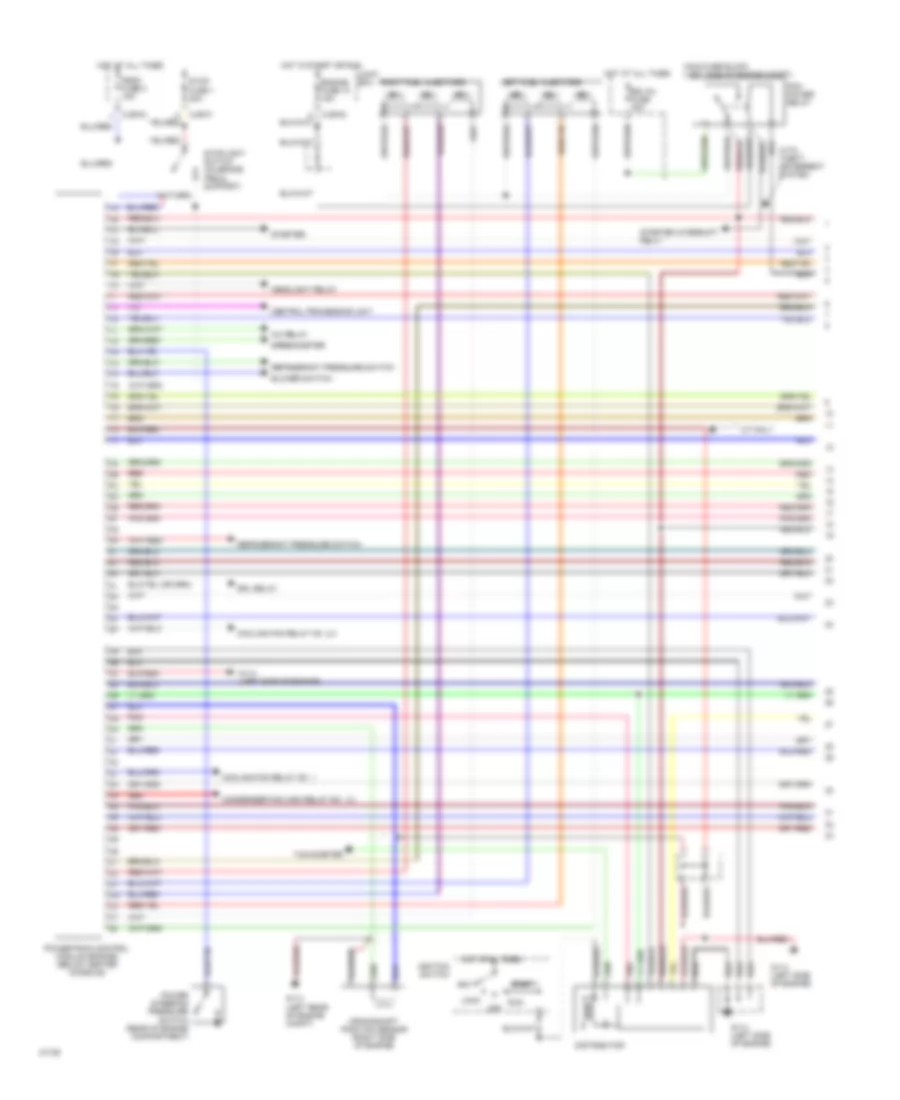
2.0L, Engine Performance Wiring Diagrams, M/T (2 of 2) for Mazda 626 DX 1994
List of elements for 2.0L, Engine Performance Wiring Diagrams, M/T (2 of 2) for Mazda 626 DX 1994:
- C-01
- California
- Cjb-03
- Clutch pedal switch (on clutch pedal support)
- Connector
- Cruise control unit
- Egr function sensor (center rear of engine compt) (california)
- Egr solenoid valve (right rear of engine compartment) (california)
- Egr solenoid valve (right rear of engine compartment) (federal)
- Egr temperature sensor (right rear of engine compt) (federal)
- Engine coolant temperature sensor (left side of engine)
- Federal
- Fuel pump
- Fuel pump relay
- Fuel tank unit
- G106 (behind left headlight)
- G114 (left rear of engine compt)
- G300 (below left front seat)
- Heated oxygen sensor (lower right side of engine, on exhaust pipe)
- Hot in run
- Hot in start or run
- Idle air control solenoid valve (left rear of engine compartment)
- Instrument cluster
- Intake air temperature sensor (left side of engine)
- Joint
- Joint box
- Joint connector
- Main fuse block (left side of engine compt)
- Malfunction indicator (check engine)
- Mass air flow sensor (left rear of engine compt)
- Meter fuse 8 15a
- Nca
- Prc solenoid valve (right rear of engine compartment)
- Purge solenoid valve (right rear of engine compartment)
- Red
- Throttle position sensor (center rear of engine)
- Wiper fuse 13 20a
- With cruise control
2.5L
2.5L, Engine Performance Wiring Diagrams (1 of 2) for Mazda 626 DX 1994
List of elements for 2.5L, Engine Performance Wiring Diagrams (1 of 2) for Mazda 626 DX 1994:
- A/c relay
- Acc
- Blower switch
- Central processing unit
- Cjb-01
- Cjb-02
- Cjb-03
- Condenser fan high relay no. 1,2
- Cooling fan relay no. 1
- Cooling fan relay no. 2,3
- Crankshaft position sensor (right side of engine)
- Distributor
- Drl relay
- Egi inj fuse 30a
- Engine fuse 10 15a
- G114 (left rear of engine compt)
- G114 (left side of engine)
- Headlight relay
- Hot at all times
- Hot in start or run
- Ignition switch
- Joint box
- Left fuel injectors
- Lock
- M/t only
- Main fuse block (left side of engine compt)
- Off
- Pcm power relay
- Pnk
- Power steering pressure switch (rear of engine compartment)
- Powertrain control module (engine) (below center console)
- Red
- Refrigerant pressure switch
- Right fuel injectors
- Room fuse 2 15a
- Run
- Speedometer
- Start
- Starter
- Starter interrupt relay
- Stop fuse 1 20a
- Stoplight switch (on brake pedal support)
- Tachometer
- With theft- deterrent system
2.5L, Engine Performance Wiring Diagrams (2 of 2) for Mazda 626 DX 1994
List of elements for 2.5L, Engine Performance Wiring Diagrams (2 of 2) for Mazda 626 DX 1994:
- (a/t)
- (m/t)
- A/t
- Alu
- C-01
- Canister purge solenoid valve (right rear of engine compt)
- Cjb-03
- Clutch pedal position switch (on clutch pedal support)
- Data link connector (left side of engine)
- Egr solenoid valve (vacuum) (right rear of engine compt)
- Egr solenoid valve (vent) (right rear of engine compt)
- Egr valve position sensor (center rear of engine)
- Engine coolant temperature sensor (right side of engine)
- Fprc solenoid valve (left side of engine)
- Fuel pump
- Fuel pump relay
- Fuel tank unit
- G106 (behind left headlight)
- G110 (left front of engine)
- G110 (left front of engine) g114 (left front of engine)
- G114 (left side of engine)
- G300 (below left front seat)
- Hot in start or run
- Idle air control solenoid valve (left side of engine)
- Instrument cluster
- Joint box
- Knock sensor (left rear of engine)
- Left heated oxygen sensor (lower left side of engine, on exhaust pipe)
- M/t
- Main fuse block (left side of engine compt)
- Malfunction indicator (check engine)
- Meter fuse 8 15a
- Nca
- Neutral position switch (left side of engine)
- Powertrain control module (transaxle) (below center of i/p)
- Red
- Right heated oxygen sensor (lower right side of engine, on exhaust pipe)
- Throttle position sensor (front top left of engine)
- Volumn air flow sensor (left side of engine)
- Vris solenoid valve no. 2 (right rear of engine compt)
- Vris solenoid valve no. 1 (right rear of engine compt)