ENGINE PERFORMANCE
1.3L
1.3L, Engine Performance Wiring Diagrams (1 of 3) for Mazda RX-7 1995

List of elements for 1.3L, Engine Performance Wiring Diagrams (1 of 3) for Mazda RX-7 1995:
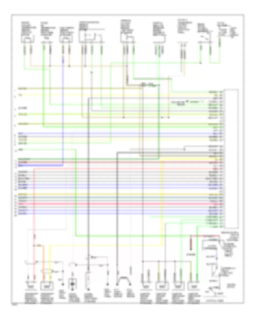
1.3L, Engine Performance Wiring Diagrams (2 of 3) for Mazda RX-7 1995
List of elements for 1.3L, Engine Performance Wiring Diagrams (2 of 3) for Mazda RX-7 1995:
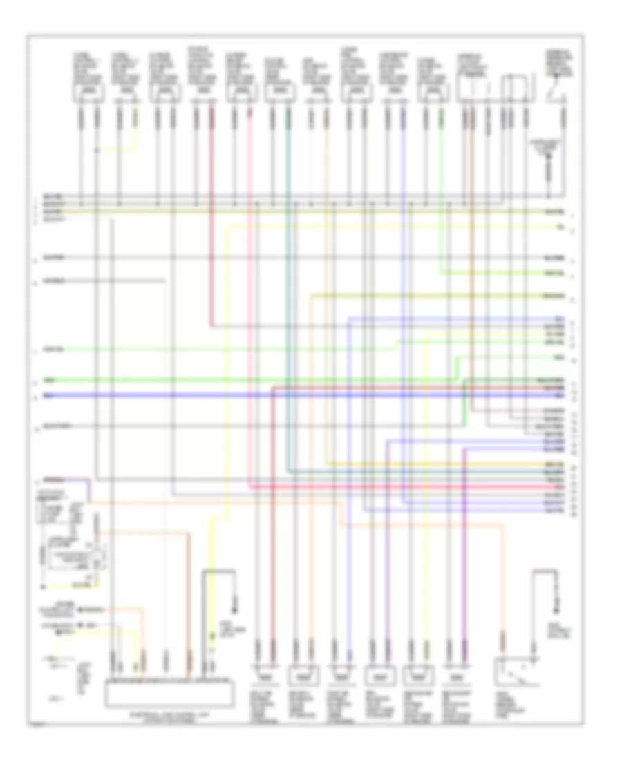
1.3L, Engine Performance Wiring Diagrams (3 of 3) for Mazda RX-7 1995
List of elements for 1.3L, Engine Performance Wiring Diagrams (3 of 3) for Mazda RX-7 1995: