ENGINE PERFORMANCE
2.5L
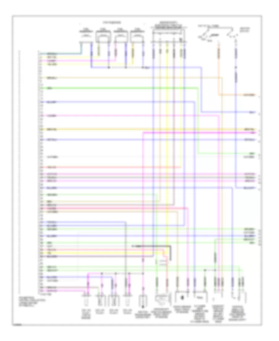
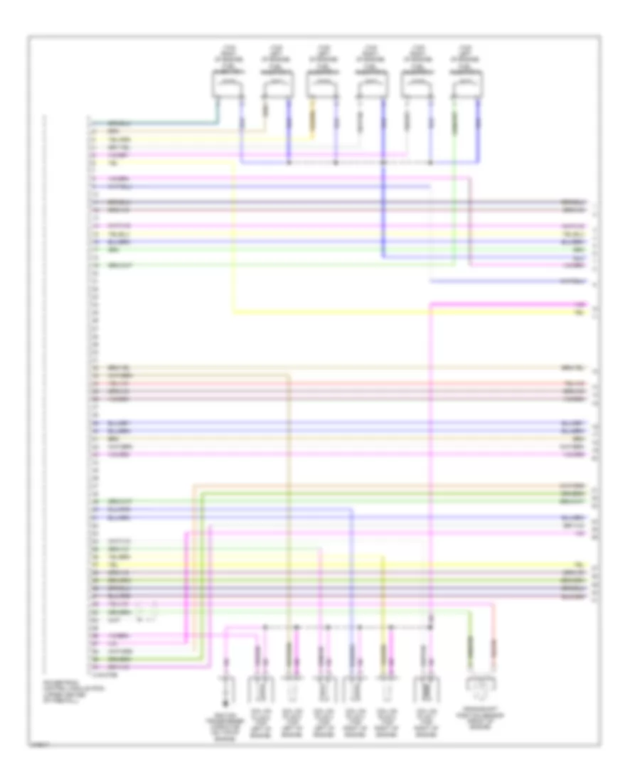
2.5L, Engine Performance Wiring Diagram, Except Hybrid (1 of 4) for Mazda Tribute Hybrid Grand Touring 2010

List of elements for 2.5L, Engine Performance Wiring Diagram, Except Hybrid (1 of 4) for Mazda Tribute Hybrid Grand Touring 2010:
- (top of engine)
- (top of engine) electronic throttle control motor
- 0140-175e
- Acc
- Camshaft position sensor (on left rear of cylinder head)
- Coil on plug 1 (top right of engine)
- Coil on plug 2 (top right of engine)
- Coil on plug 3 (top right of engine)
- Coil on plug 4 (top left of engine)
- Crankshaft position sensor (front of engine block)
- Cylinder head temperature (cht) sensor (on right front of cylinder head)
- Fuel injector 1
- Fuel injector 2
- Fuel injector 3
- Fuel injector 4
- Hot at all times
- Ignition switch
- Ignition transformer capacitor (on top of engine)
- Knock sensor
- Manifold absolute pressure (map) sensor (front of engine compt)
- Off
- Powertrain control module (pcm) (upper center of firewall)
- Run
- Start
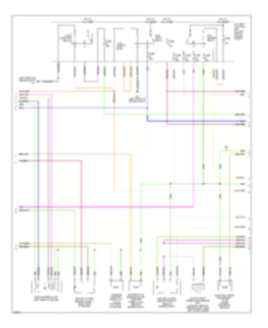
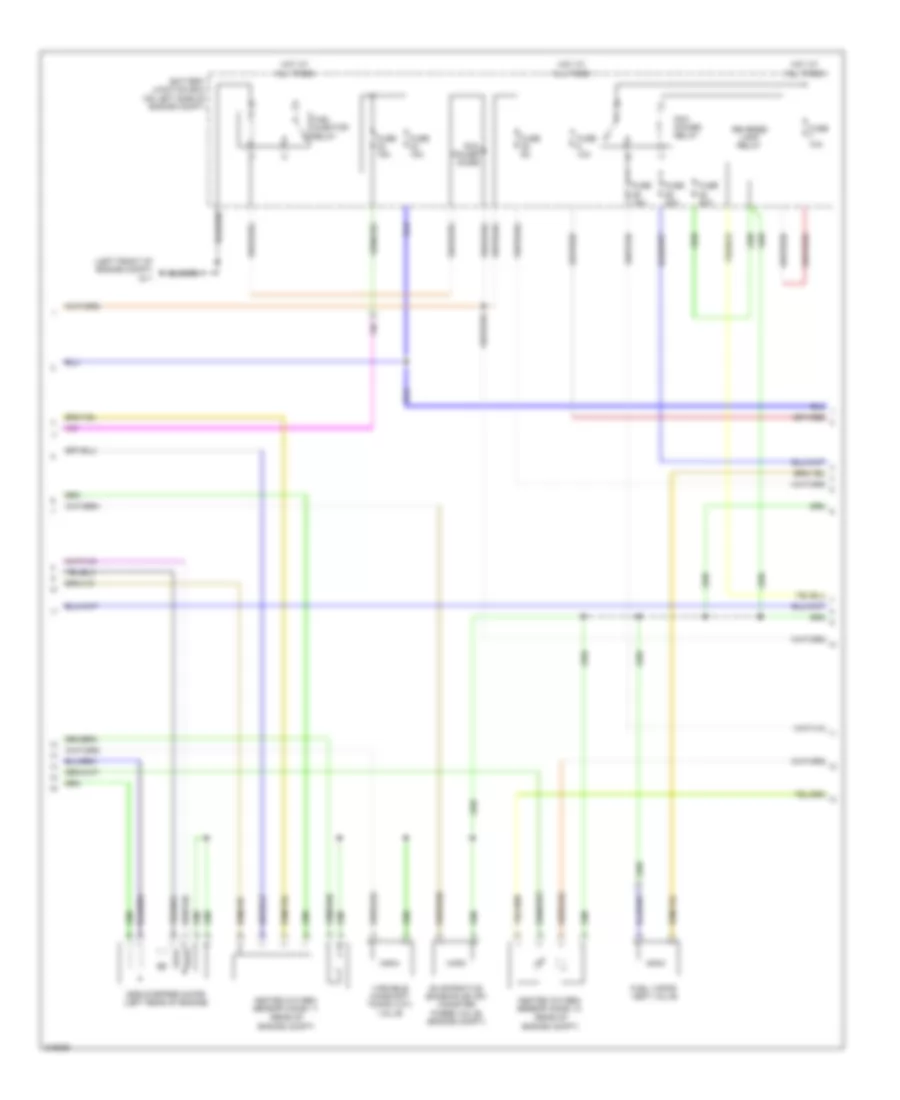
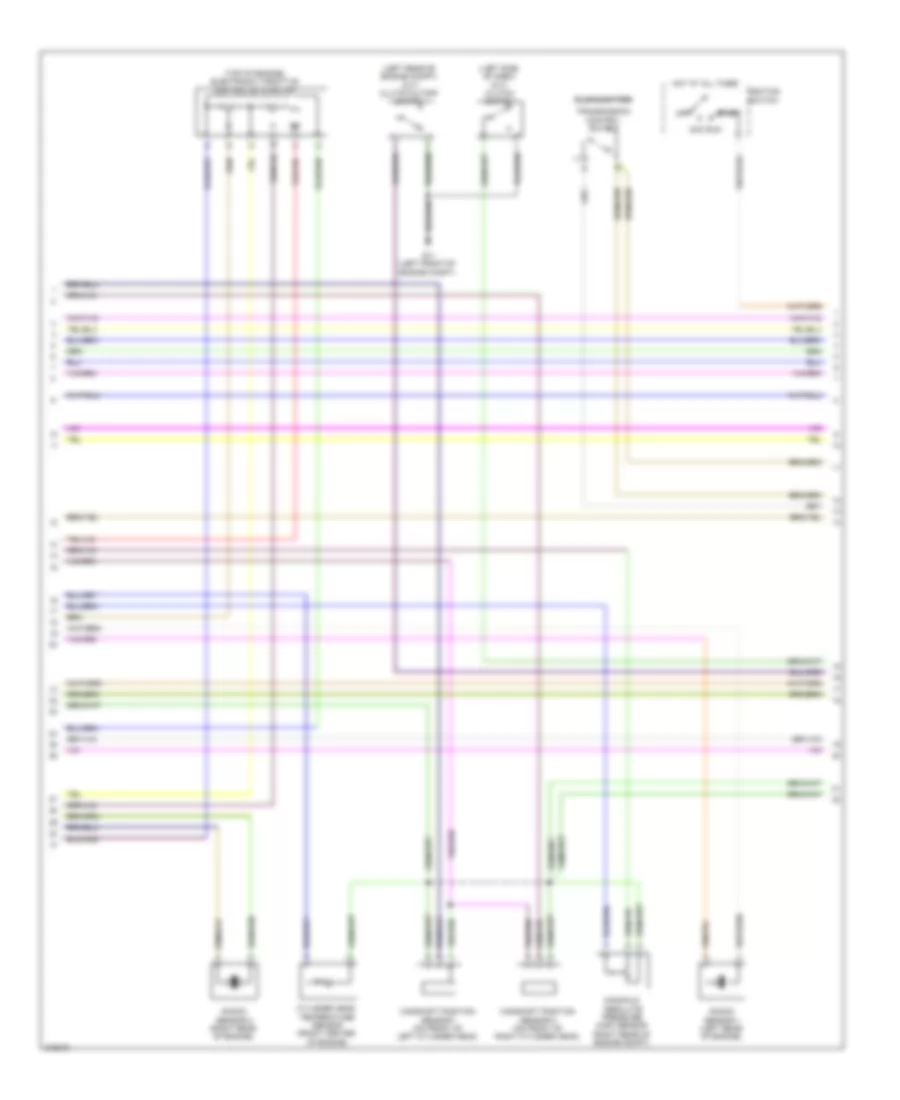
2.5L, Engine Performance Wiring Diagram, Except Hybrid (2 of 4) for Mazda Tribute Hybrid Grand Touring 2010
List of elements for 2.5L, Engine Performance Wiring Diagram, Except Hybrid (2 of 4) for Mazda Tribute Hybrid Grand Touring 2010:
- (left front of engine compt) g11
- (rear of engine compt)
- Battery junction box (on left side of engine compt)
- Egr stepper motor (left rear of engine)
- Electric vapor management valve (under center of vehicle)
- Evaporative emission (evap) canister purge valve (rear of engine compt)
- Fuel injector relay
- Fuel pump diode
- Fuel pump relay
- Fuse 10a
- Fuse 15a
- Fuse 20a
- G11 (left front of engine compt)
- Heated oxygen sensor (ho2s) 11 (right side of engine)
- Heated oxygen sensor (ho2s) 12
- Hot at all times
- M/t
- Output shaft speed (oss) sensor (m/t) (on right rear of transmission, near left axle flange)
- Pcm power relay
- Variable camshaft timing (vct) valve (top front of engine)
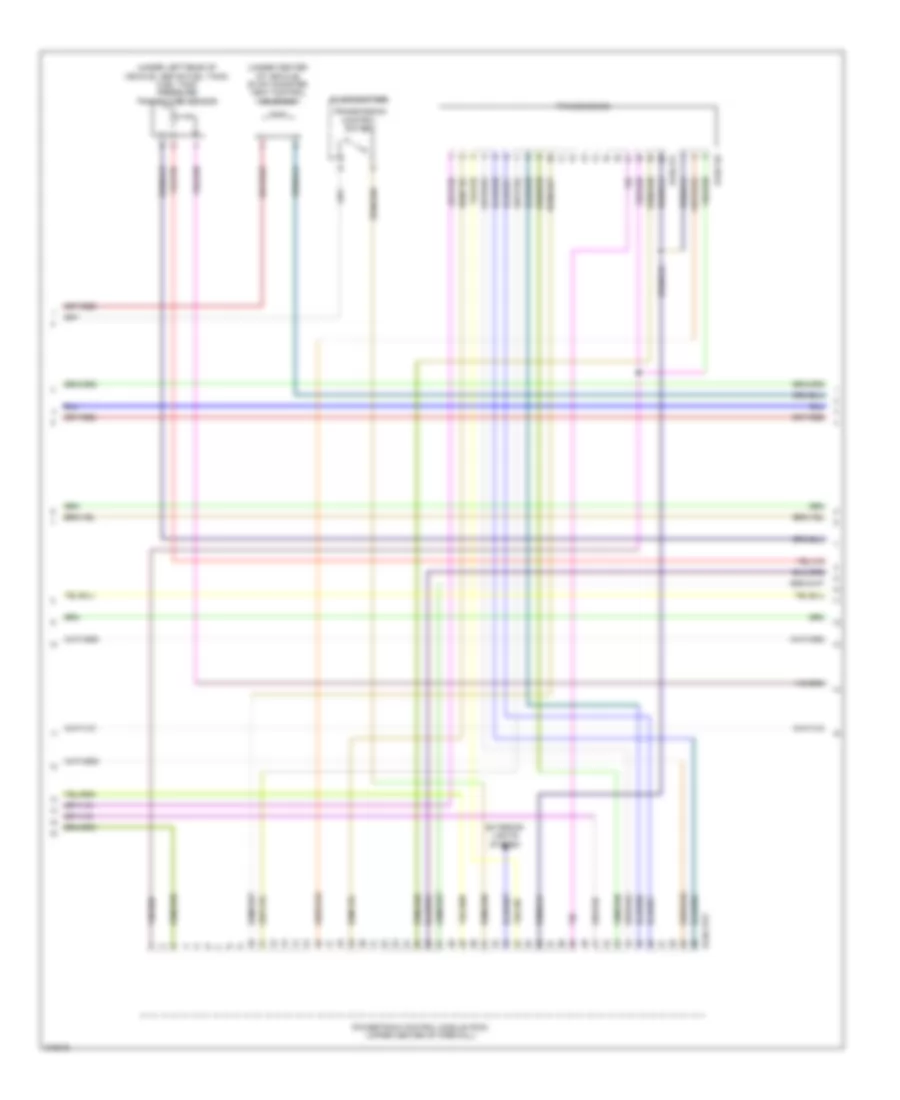
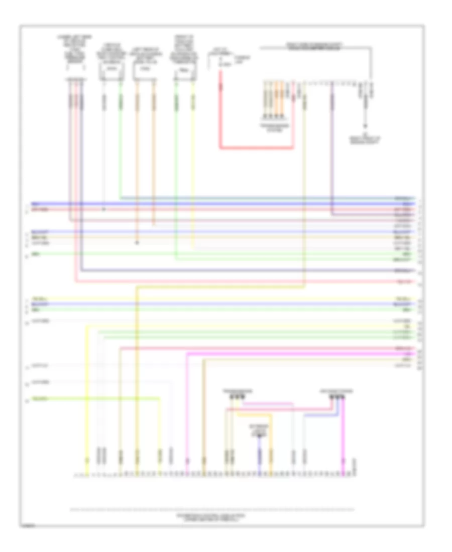
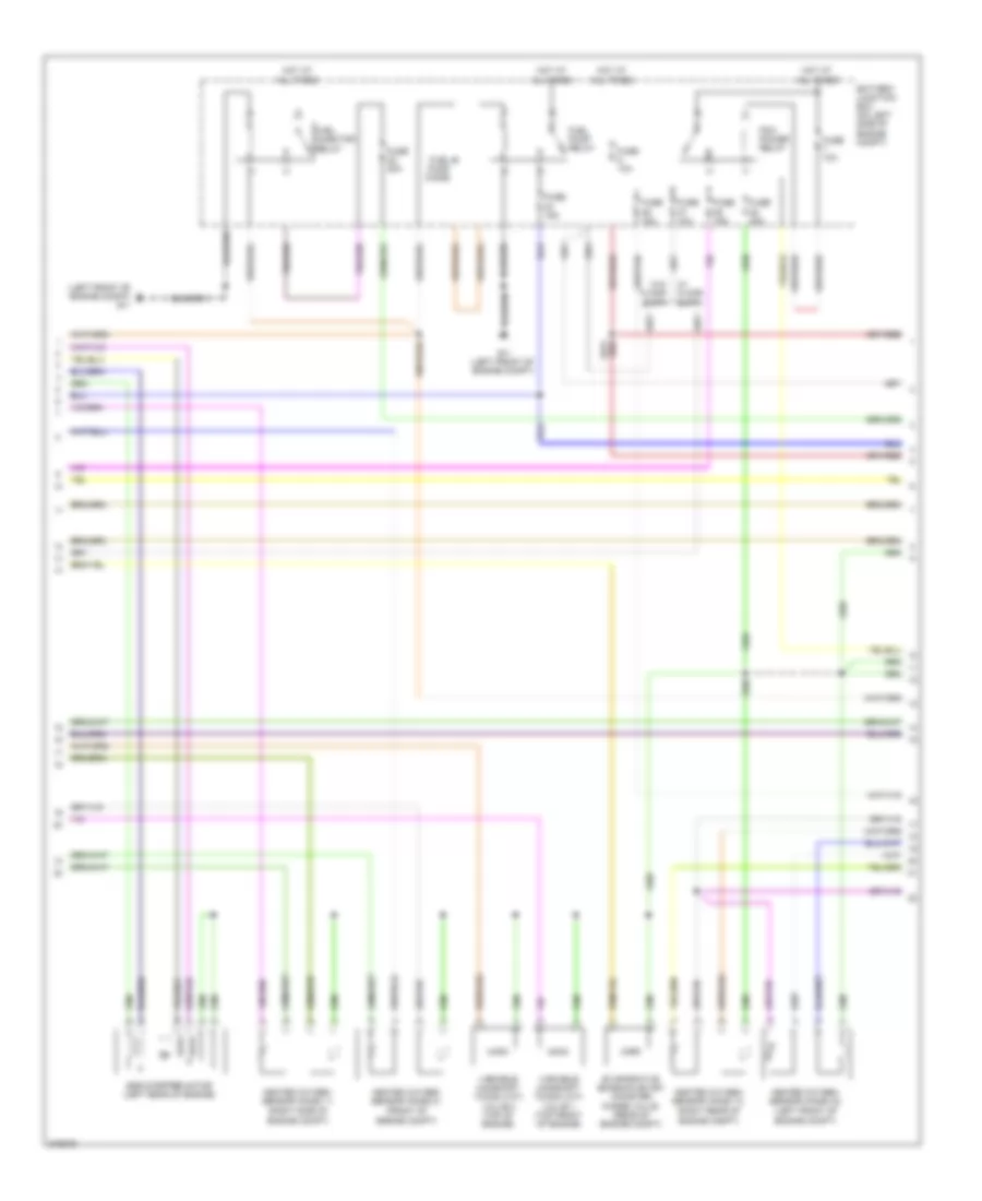
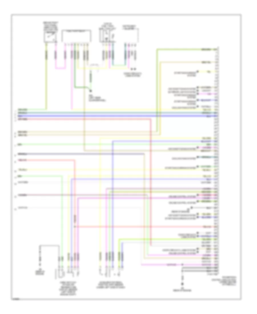
2.5L, Engine Performance Wiring Diagram, Except Hybrid (3 of 4) for Mazda Tribute Hybrid Grand Touring 2010
List of elements for 2.5L, Engine Performance Wiring Diagram, Except Hybrid (3 of 4) for Mazda Tribute Hybrid Grand Touring 2010:
- (under center of vehicle) evap canister vent control solenoid
- (under left rear of vehicle, above fuel tank) fuel tank pressure transducer sensor
- 0140-131
- 0140-132
- 0140-175t
- Exterior lights system
- Floor shifter
- Powertrain control module (pcm) (upper center of firewall)
- Transmission
- Transmission control switch
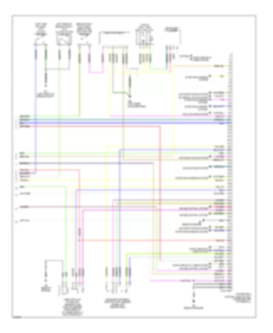
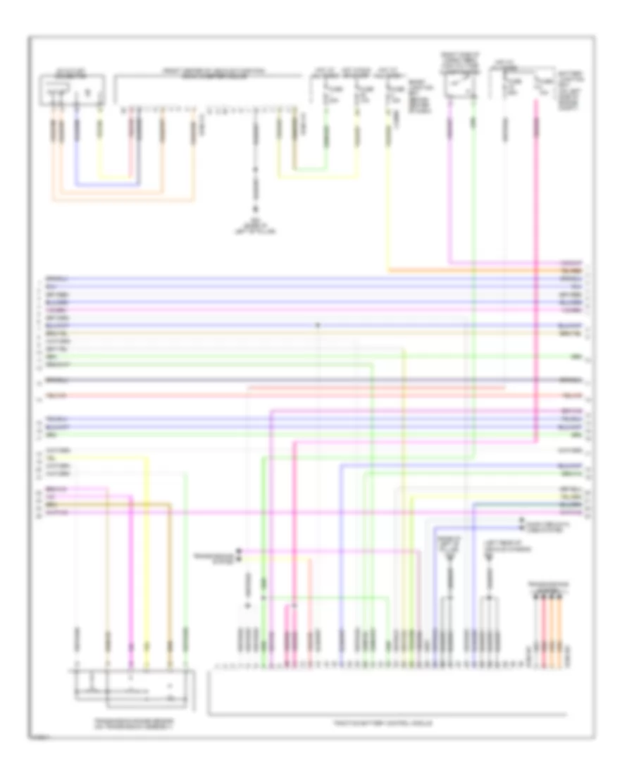
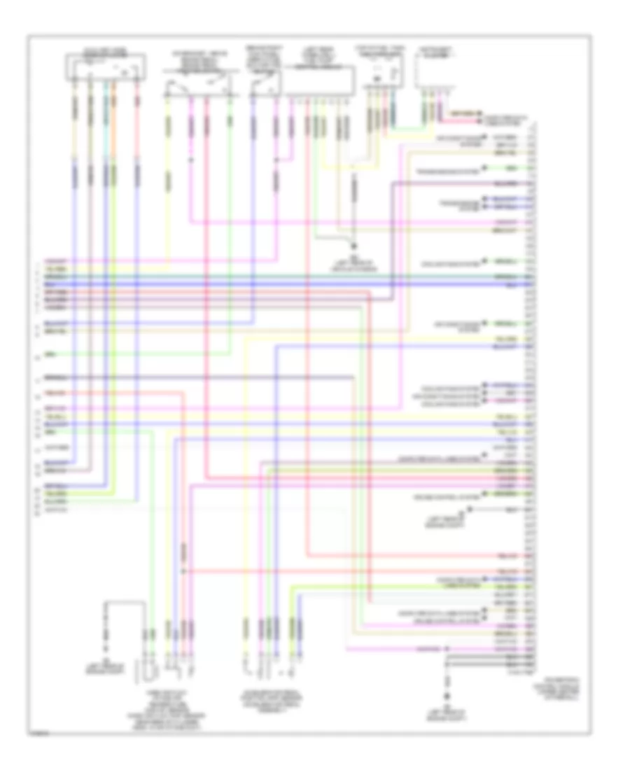
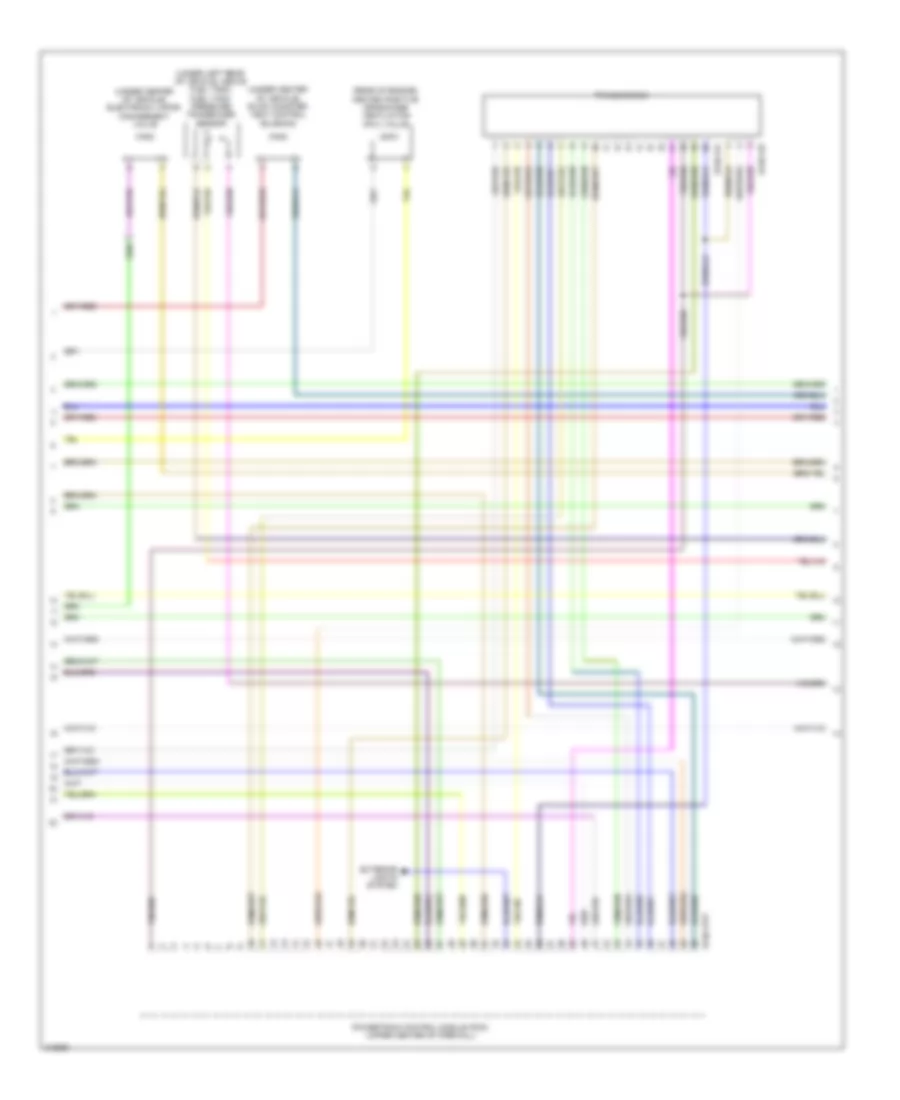
2.5L, Engine Performance Wiring Diagram, Except Hybrid (4 of 4) for Mazda Tribute Hybrid Grand Touring 2010
List of elements for 2.5L, Engine Performance Wiring Diagram, Except Hybrid (4 of 4) for Mazda Tribute Hybrid Grand Touring 2010:
- (behind right kick panel) inertia fuel shutoff (ifs) switch
- (left rear of engine compt)
- (left side of dash) (m/t) clutch switch
- (m/t) clutch cutoff switch
- (top of fuel tank)
- 0140-175b
- Accelerator pedal position (app) sensor (under left side of dash)
- Air conditioning system
- Computer data lines system
- Cooling fans system
- Cruise control system
- Exterior lights system starting/charging system
- Fuel pump relay
- Fuel tank unit
- G11 (left front of engine compt)
- G22 (left rear quarterpanel)
- G9 (rear of engine)
- Instrument cluster
- Mass air flow/ intake air temperature (maf/iat) sensor (near rear of cylinder head, in air intake duct)
- Powertrain control module (pcm) (upper center of firewall)
- Starting/charging system
2.5L, Engine Performance Wiring Diagram, Hybrid (1 of 5) for Mazda Tribute Hybrid Grand Touring 2010
List of elements for 2.5L, Engine Performance Wiring Diagram, Hybrid (1 of 5) for Mazda Tribute Hybrid Grand Touring 2010:
- (engine compt) electronic throttle control (etc) motor
- (top of engine)
- 0140-175e
- Acc
- Camshaft position sensor (on left rear of cylinder head)
- Coil on plug 1 (top of engine)
- Coil on plug 2
- Coil on plug 3
- Coil on plug 4
- Crankshaft position sensor (front right of engine)
- Cylinder head temperature sensor (on right front of cylinder head)
- Fuel injector 1
- Fuel injector 2
- Fuel injector 3
- Fuel injector 4
- Hot at all times
- Ignition switch
- Ignition transformer capacitor 1
- Knock sensor (right front of engine)
- Manifold absolute pressure (map) sensor (front of engine compt)
- Nca
- Off
- Powertrain control module (pcm) (upper center of firewall)
- Run
- Start
2.5L, Engine Performance Wiring Diagram, Hybrid (2 of 5) for Mazda Tribute Hybrid Grand Touring 2010
List of elements for 2.5L, Engine Performance Wiring Diagram, Hybrid (2 of 5) for Mazda Tribute Hybrid Grand Touring 2010:
- (left front of engine compt) g11
- (rear of engine compt)
- Battery junction box (on left side of engine compt)
- Egr stepper motor (left rear of engine)
- Evaporative emission (evap) canister purge valve (engine compt)
- Fuel injector relay
- Fuel vapor vent valve
- Fuse 10a
- Fuse 15a
- Fuse 20a
- Fuse 5a
- Heated oxygen sensor (ho2s) 11
- Heated oxygen sensor (ho2s) 12
- Hot at all times
- Pcm power diode
- Pcm power relay
- Reverse lamp relay
- Variable camshaft timing (vct) valve
2.5L, Engine Performance Wiring Diagram, Hybrid (3 of 5) for Mazda Tribute Hybrid Grand Touring 2010
List of elements for 2.5L, Engine Performance Wiring Diagram, Hybrid (3 of 5) for Mazda Tribute Hybrid Grand Touring 2010:
- (front of traction battery) auxiliary evaporator discharge air thermistor
- (left rear of vehicle chassis) battery zone valve
- (right side of engine compt) dc/dc converter module
- (under left rear of vehicle, above fuel tank) fuel tank pressure sensor
- (vehicle overview) evap canister vent control solenoid
- 0130-109
- 0130-110
- 0130-111
- 0130-112
- 0140-175t
- 150a
- Air conditioning system
- Exterior lights system
- Fusible link
- G7 (right front of engine compt)
- Hot at all times
- Powertrain control module (pcm) (upper center of firewall)
- Red
- Transmissions system
2.5L, Engine Performance Wiring Diagram, Hybrid (4 of 5) for Mazda Tribute Hybrid Grand Touring 2010
List of elements for 2.5L, Engine Performance Wiring Diagram, Hybrid (4 of 5) for Mazda Tribute Hybrid Grand Touring 2010:
- (base of left "b" pillar) g19
- (front center of vehicle floor pan) dc/ac inverter module
- (left rear of vehicle chassis) g24
- (right side of cargo area) high voltage cutoff switch
- 0130-101
- 0130-103
- 0130-113
- 0130-114
- Ac outlet connector
- Battery junction box (on left side of engine compt)
- Computer data lines system
- Fuse 10a
- Fuse 15a
- Fuse 30a
- Fuse 50a
- G20 (base of left "b" pillar)
- Hot at all times
- Hot in run or start
- J-2280d
- Outlet
- Red
- Smart junction box (behind center of dash)
- Traction battery control module
- Transmission range sensor (on transmission assembly)
- Transmissions system
2.5L, Engine Performance Wiring Diagram, Hybrid (5 of 5) for Mazda Tribute Hybrid Grand Touring 2010
List of elements for 2.5L, Engine Performance Wiring Diagram, Hybrid (5 of 5) for Mazda Tribute Hybrid Grand Touring 2010:
- (behind right kick panel) inertia fuel shutoff (ifs) switch
- (left rear wheelwell) fuel pump control module
- (on bracket, above brake pedal) brake pedal position switch
- (top of fuel tank) fuel tank unit
- 0140-175b
- Accelerator pedal position (app) sensor (accelerator pedal assembly)
- Air conditioning system
- Auxiliary mode door actuator
- Computer data lines system
- Cooling fans system
- Cruise control system
- G23 (left rear of vehicle chassis)
- G6 (left rear of engine compt)
- Instrument cluster
- Mass air flow/ intake air temperature (maf/iat) sensor (mass air flow (maf) sensor: near rear of cylinder head, in air intake duct)
- Powertrain control module (upper center of firewall)
- Red
- Transmissions system
3.0L
3.0L, Engine Performance Wiring Diagram (1 of 5) for Mazda Tribute Hybrid Grand Touring 2010
List of elements for 3.0L, Engine Performance Wiring Diagram (1 of 5) for Mazda Tribute Hybrid Grand Touring 2010:
- (top left of engine)
- (top right of engine)
- (top right of engine) fuel injector 1
- 0140-275e
- Coil on plug 1 (top right of engine)
- Coil on plug 2 (top right of engine)
- Coil on plug 3 (top right of engine)
- Coil on plug 4 (top left of engine)
- Coil on plug 5 (top left of engine)
- Coil on plug 6 (top left of engine)
- Crankshaft position sensor (front of engine)
- Fuel injector 2
- Fuel injector 3
- Fuel injector 4
- Fuel injector 5
- Fuel injector 6
- Ignition transformer capacitor (on top of engine)
- Powertrain control module (pcm) (upper center of firewall)
3.0L, Engine Performance Wiring Diagram (2 of 5) for Mazda Tribute Hybrid Grand Touring 2010
List of elements for 3.0L, Engine Performance Wiring Diagram (2 of 5) for Mazda Tribute Hybrid Grand Touring 2010:
- (left rear of engine compt) (m/t) clutch cutoff switch
- (left side of dash) (m/t) clutch switch
- (top of engine) electronic throttle control (etc) motor
- Acc
- Camshaft position sensor 1 (on front of left cylinder head)
- Camshaft position sensor 2 (on front of right cylinder head)
- Cylinder head temperature sensor (front center of engine)
- Floor shifter
- G11 (left front of engine compt)
- Hot at all times
- Ignition switch
- Knock sensor 1 (left rear of engine)
- Knock sensor 2 (right rear of engine)
- Manifold absolute pressure (map) sensor (right rear of engine compt)
- Off
- Run
- Start
- Transmission control switch
3.0L, Engine Performance Wiring Diagram (3 of 5) for Mazda Tribute Hybrid Grand Touring 2010
List of elements for 3.0L, Engine Performance Wiring Diagram (3 of 5) for Mazda Tribute Hybrid Grand Touring 2010:
- (front of engine compt)
- (left front of engine compt)
- (left front of engine compt) g11
- (right rear of engine compt)
- (right side of engine compt)
- Battery junction box (on left side of engine compt)
- Egr stepper motor (left rear of engine)
- Evaporative emission (evap) canister purge valve (rear of engine compt)
- Fuel injector relay
- Fuel pump diode
- Fuel pump relay
- Fuse 10a
- Fuse 15a
- Fuse 20a
- G11 (left front of engine compt)
- Heated oxygen sensor (ho2s) 11
- Heated oxygen sensor (ho2s) 12
- Heated oxygen sensor (ho2s) 21
- Heated oxygen sensor (ho2s) 22
- Hot at all times
- Pcm power relay
- Variable camshaft timing (vct) valve 1 (top front of engine)
- Variable camshaft timing (vct) valve 2 (top of engine)
- W/ floor shift
- W/o floor shift
3.0L, Engine Performance Wiring Diagram (4 of 5) for Mazda Tribute Hybrid Grand Touring 2010
List of elements for 3.0L, Engine Performance Wiring Diagram (4 of 5) for Mazda Tribute Hybrid Grand Touring 2010:
- (rear of engine) heated positive crankcase ventilation (pcv) valve
- (under center of vehicle) electronic vapor management valve
- (under center of vehicle) evap canister vent control solenoid
- (under left rear of vehicle, above fuel tank) fuel tank pressure transducer sensor
- 0140-131
- 0140-132
- 0140-175t
- Exterior lights system
- Powertrain control module (pcm) (upper center of firewall)
- Transmission
3.0L, Engine Performance Wiring Diagram (5 of 5) for Mazda Tribute Hybrid Grand Touring 2010
List of elements for 3.0L, Engine Performance Wiring Diagram (5 of 5) for Mazda Tribute Hybrid Grand Touring 2010:
- (behind right kick panel) inertia fuel shutoff (ifs) switch
- (top of fuel tank) fuel tank unit
- 0140-175b
- Accelerator pedal position (app) sensor (under left side of dash)
- Air conditioning system
- Computer data lines system
- Cooling fans system
- Cruise control system
- Exterior lights system
- Fuel pump relay
- G22 (left rear quarterpanel)
- G9 (rear of engine)
- Instrument cluster
- Mass air flow/ intake air temperature (maf/iat) sensor (left side of engine compt)
- Powertrain control module (pcm) (upper center of firewall)
- Starting/charging system