ENGINE PERFORMANCE
2.6L
2.6L, Engine Performance Wiring Diagram (1 of 3) for Mercedes-Benz C240 2005

List of elements for 2.6L, Engine Performance Wiring Diagram (1 of 3) for Mercedes-Benz C240 2005:
- (left side of engine compt) w16/3
- (rear of right cyl bank) egr vacuum transducer
- (top of engine) air pump switchover sensor
- Accelerator pedal sensor (above pedal assembly)
- Acf vlv
- Activated charcoal filter shutoff valve (above right rear wheelwell)
- Air pump
- Aps vlv
- Can h
- Can l
- Clutch pedal switch
- Coil 5a
- Computer data lines system
- Cooling fans system
- Data link connector
- Diag
- Egr
- Engine control module (me-sfi) (left rear of engine compt)
- Fan
- Ftp +5v
- Ftp -
- Ftp sig
- Fuel injectors
- Fuel pump
- Fuel tank pressure sensor (under left rear seat)
- Gen
- Generator
- Inj 2
- Inj 3
- Inj 5
- Inj 6
- Kickdown switch (incorporated w/ accelerator pedal assembly)
- Kickdwn
- L o2 d
- L o2 s
- Left o2 sensor (downstream) (left front of vehicle, in exhaust)
- Nca
- O2 d
- P/n
- R o2 d
- R o2 u
- Right o2 sensor (downstream) (right front of vehicle, in exhaust)
- Sp1m
- Sp1s
- Sp2m
- Sp2s
- Start
- Tna
- Usp1
- Variable intake manifold switchover valve
- Vims vlv
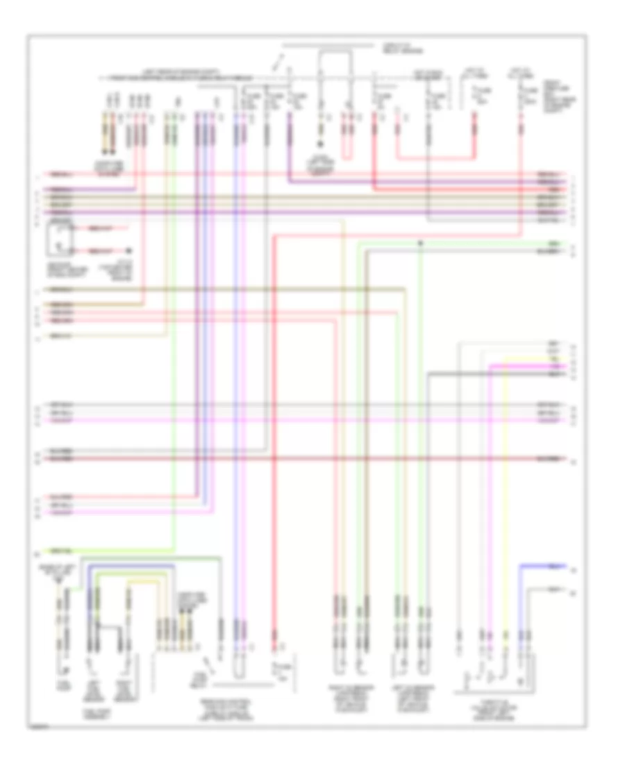
2.6L, Engine Performance Wiring Diagram (2 of 3) for Mercedes-Benz C240 2005
List of elements for 2.6L, Engine Performance Wiring Diagram (2 of 3) for Mercedes-Benz C240 2005:
- (base of left "b" pillar) w18
- (left rear of engine compt) front sam control module w/ fuse & relay module
- 87 m1
- 87 m2
- Air pump (front center of eng compt)
- C10
- C13
- C17
- Can h
- Can l
- Circuit 87 relay (engine)
- Computer data lines system
- Cpp
- Front pre-fuse box (right rear of engine compt)
- Fuel pump
- Fuel pump assembly
- Fuel pump relay
- Fuse 15a
- Fuse 200a
- Fuse 25a
- Fuse 5a
- Fuse 60a
- Hot at all times
- Hot in run or start
- Left fuel level sensor
- Left o2 sensor (upstream) (left front of vehicle, in exhaust)
- Nca
- Of engine compt)
- Rear sam control module w/ fuse & relay module (left side of trunk)
- Red
- Right fuel level sensor
- Right o2 sensor (upstream) (right front of vehicle, in exhaust)
- Throttle valve actuator (front left side of engine)
- Tna
- W11/3 (top center front of engine)
- W16/3 (left side
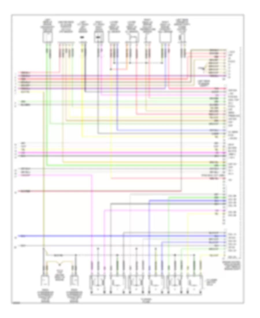
2.6L, Engine Performance Wiring Diagram (3 of 3) for Mercedes-Benz C240 2005
List of elements for 2.6L, Engine Performance Wiring Diagram (3 of 3) for Mercedes-Benz C240 2005:
- (center rear of intake manifold) hot film maf sensor
- (left cyl bank) left knock sensor
- (left rear corner of engine compt) purge control valve
- (left rear of engine compt)
- (left rear of engine) crankshaft position sensor
- (lower right front of engine) oil sensor
- (pins 29-38: not used)
- (right cyl bank) right knock sensor
- (right front of engine) camshaft hall sensor
- (right front of engine) coolant temperature sensor
- +5v
- Akf
- Ap mo+
- Ap mo-
- Ckp
- Clear
- Cmp sig
- Coil 1a
- Coil 1b
- Coil 2a
- Coil 2b
- Coil 3a
- Coil 3b
- Coil 4a
- Coil 4b
- Coil 5b
- Coil 6a
- Coil 6b
- Cool tmp
- Cylinder ignition coils
- Ea ip1s
- Ea ip2s
- Engine control module (me-sfi) (left rear of engine compt)
- Inj 1
- Inj 4
- L ks -
- L ks sig
- L o2 d
- L o2 u
- Maf
- Maf +5v
- Maf -
- Maf sig
- Mr ip
- O2 u
- Oil sens
- Pnk
- Press sig
- R ks -
- R ks sig
- R o2 d
- R o2 u
- Radio interference suppression capacitor 1 (top of engine)
- Radio interference suppression capacitor 2 (top of engine)
- Red
- Sens -
- To spark plugs
- Uref 2
- W11/3 (top center front of engine)
- W16/5