ENGINE PERFORMANCE
1.8L TURBO
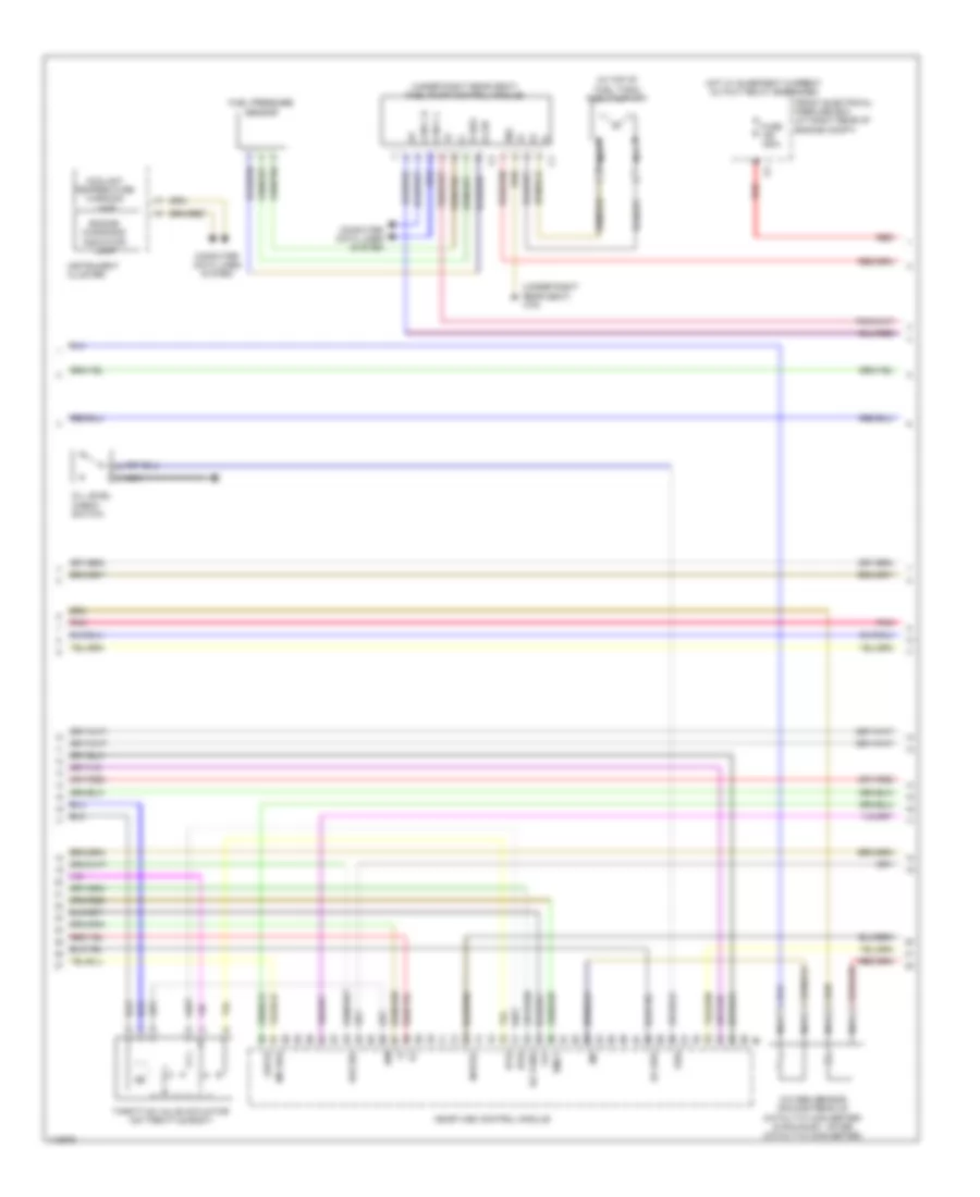
1.8L Turbo, Engine Performance Wiring Diagram (1 of 4) for Mercedes-Benz C250 2013

List of elements for 1.8L Turbo, Engine Performance Wiring Diagram (1 of 4) for Mercedes-Benz C250 2013:
- (+)
- (+) 5v
- (-)
- (above of 1, 2, 3 & 4 cylinders) fuel injectors
- (above of 1, 2, 3 & 4 cylinders) ignition coil cylinders
- (right front of engine) w11
- At zue1
- At zue2
- At zue3
- At zue4
- Charge air temperature sensor (left rear of engine)
- Coolant temperature sensor
- Crankshaft hall sensor
- Dcm
- Dcp
- Ea lds
- Ev1
- Ev2
- Ev3
- Ev4
- Front knock sensor (left side of engine)
- Intake manifold swirl flap actuator motor
- Interference suppression capacitor
- Ks1 sig
- Kwdga
- Lin c1
- Lshu1
- Lsu1n
- Lsu1s
- Lsuius
- Me-sfi (me) control module
- Nca
- Nwhgsa
- Nwhgse
- Nwva2
- Pnk
- Pressure sensor downstream of throttle valve
- Pressure sensor upstream of compressor impeller
- Pressure sensor upstream of throttle valve
- Rail pressure sensor (on fuel rail)
- Right knock sensor (between cylinder banks)
- Sig
- Spark plug
- Starting/charging system
- Swirl flap actuator motor
- Swirl flap hall sensor
- X26/39
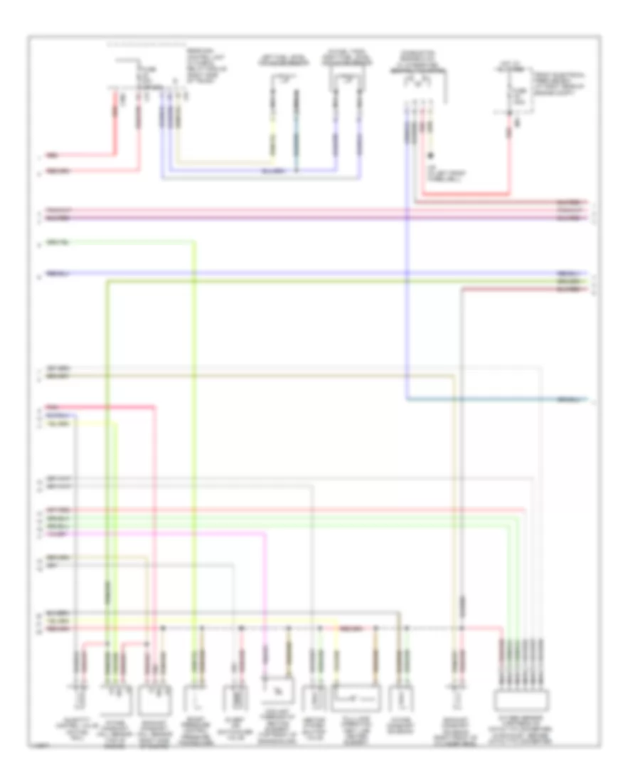
1.8L Turbo, Engine Performance Wiring Diagram (2 of 4) for Mercedes-Benz C250 2013
List of elements for 1.8L Turbo, Engine Performance Wiring Diagram (2 of 4) for Mercedes-Benz C250 2013:
- (+)
- (+) sh
- (-)
- (in top of fuel tank) fuel pump (fp)
- (under right rear seat) fuel pump control module
- (under right rear seat) w76
- +5v
- 30g
- Can c h
- Can c l
- Computer data lines system
- Coolant temperature warning lamp
- E rds
- Ea tans
- Ea uds
- Engine diagnosis indicator lamp
- Front electrical prefuse box (at right rear of engine compt)
- Fuel pressure sensor
- Fuse 150a
- Hot w/ quiescent current cutout relay energized
- Instrument cluster
- Ip1s
- Ip2s
- Ipm
- Ks2 sig
- Lsu1s
- Me-sfi (me) control module
- Mr uds
- Nca
- Nwve2
- Oil level check switch
- Oss
- Oxygen sensor (downstream of catalytic converter) (in exhaust, after catalytic converter)
- Pnk
- Red
- Throttle valve actuator (on throttle body)
- Tmot
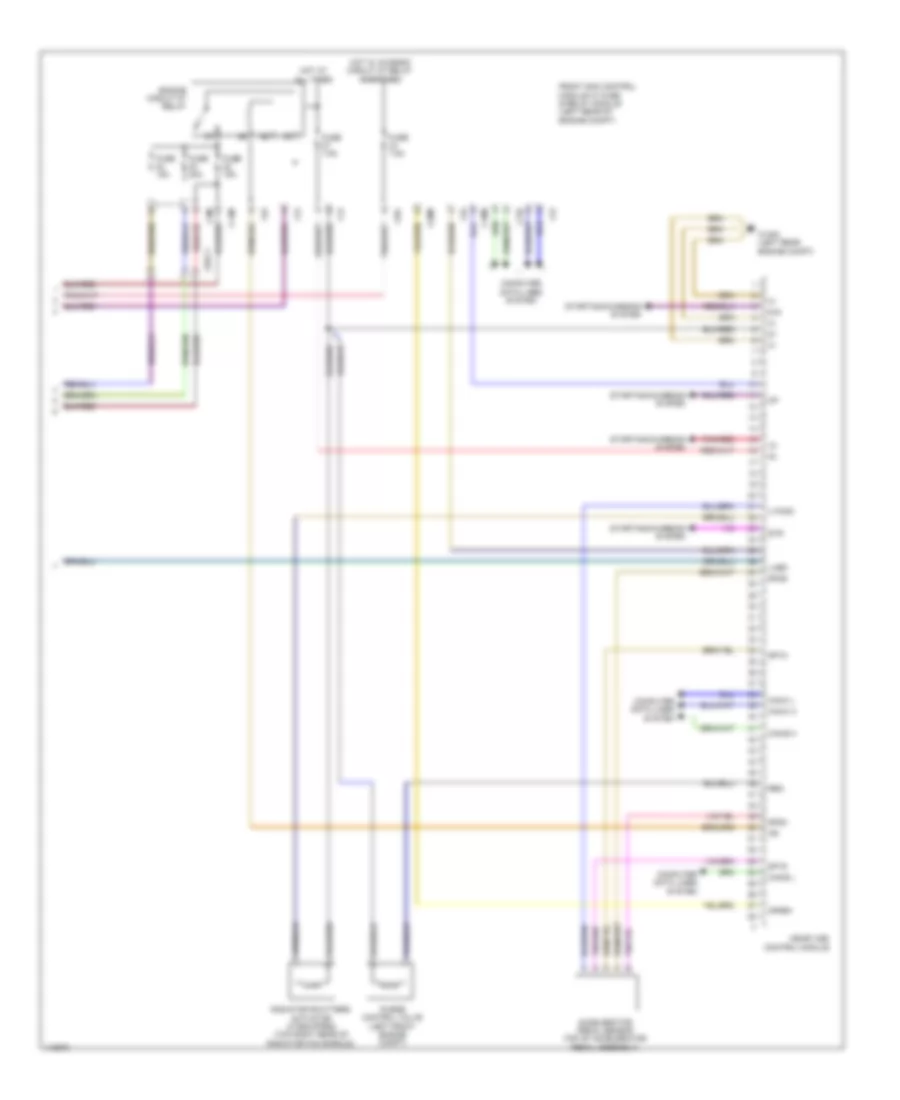
1.8L Turbo, Engine Performance Wiring Diagram (3 of 4) for Mercedes-Benz C250 2013
List of elements for 1.8L Turbo, Engine Performance Wiring Diagram (3 of 4) for Mercedes-Benz C250 2013:
- (+)
- (-)
- (in fuel tank) right fuel level indicator sensor
- Boost pressure control pressure transducer
- C30g
- C3i
- C9i
- Combustion engine & a/c w/ integrated control fan motor
- Coolant thermostat heating element (top front of engine block)
- Divert air switchover valve
- Exhaust camshaft hall sensor (right side of engine)
- Exhaust camshaft solenoid (right front of cylinder head)
- Front electrical prefuse box (at right rear of engine compt)
- Full-load operation vent line heater element
- Fuse 100a
- Fuse 20a (or 25a)
- Heating system shutoff valve
- Hot at all times
- Intake camshaft hall sensor (top of engine)
- Intake camshaft solenoid
- Left fuel level indicator sensor
- Mr1
- Nca
- Oxygen sensor (upstream of catalytic converter) (in exhaust, before catalytic converter)
- Pnk
- Quantity control valve (on fuel rail)
- Rear sam control unit w/ fuse & relay module (right side of trunk)
- Red
- Sig
- W9 (in left front wheelwell)
1.8L Turbo, Engine Performance Wiring Diagram (4 of 4) for Mercedes-Benz C250 2013
List of elements for 1.8L Turbo, Engine Performance Wiring Diagram (4 of 4) for Mercedes-Benz C250 2013:
- 87m
- Accelerator pedal sensor (top of accelerator pedal assembly)
- C14m
- C18m
- C19i
- C20m
- C2i
- C3m
- C4i
- C6i
- C9g
- Can c h
- Can c l
- Can e h
- Can e l
- Computer data lines system
- Crash
- Engine circuit 87 relay
- Front sam control module w/ fuse & relay module (left rear of engine compt)
- Fuse 15a
- Fuse 20a
- Fuse 7.5a
- Hot at all times
- Hot w/ chassis circuit 87 relay energized
- Lues
- Me-sfi (me) control module
- Pnk/red
- Purge control valve (left front engine compt)
- Radiator shutters actuator (if equipped) (top right rear of radiator fan shroud)
- Reg
- Sp1m
- Sp1s
- Sp2m
- Sp2s
- Starting/charging system
- Str
- U pwg1
- W16/5 (left rear engine compt)
- X26-c1