ENGINE PERFORMANCE
2.8L
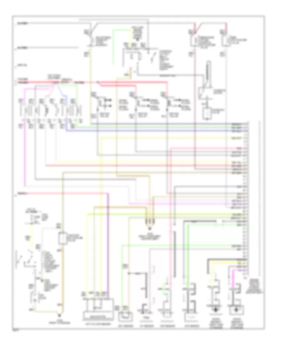
2.8L, Engine Performance Wiring Diagrams (1 of 2) for Mercedes-Benz C280 1995

List of elements for 2.8L, Engine Performance Wiring Diagrams (1 of 2) for Mercedes-Benz C280 1995:
- (before
- (below center of trunk)
- (center rear of engine compt.)
- (in left component compt.)
- (in right component compt.)
- 15a
- 15u
- 30a
- 30z
- 30a
- 87e
- 87m
- 87u
- Asr/sps control module
- Cc/isc control module
- Check engine light 2f
- Cruise control system
- Data link connector (dtc readout) (in right component compt.)
- Diagnostic module (obd-ii)
- Diagnostic module (obd-ii) generic scan tool connector (right side of left footwell)
- Ea/cc/isc control module
- Engine control module (hfm-sfi) (in right component compt.)
- Fuel pump
- Fuel pump relay module
- Fuse 15a
- Fuse 7.5a
- Fuse box
- G104 (left component compartment)
- G105 (right component compartment)
- G405 (right rear wheelhouse)
- Hot at all times
- Instrument cluster
- Nca
- O2s 1
- O2s 2 (after twc)
- O2s 2 heater relay module (after twc)
- Overvoltage protection relay module (in right component compt.)
- Pnk/ red
- Pnk/red
- Purge control valve
- Rear fuse box
- Red
- Solid state
- Starter
- Terminal block
- Trans- mission overload protection switch
- Twc)
- Upshift delay switch- over valve
- W/ asr
- W/o asr
2.8L, Engine Performance Wiring Diagrams (2 of 2) for Mercedes-Benz C280 1995
List of elements for 2.8L, Engine Performance Wiring Diagrams (2 of 2) for Mercedes-Benz C280 1995:
- (left side
- (right side
- Adjustable camshaft timing solenoid
- Air pump
- Air pump relay module (in left component compart- ment)
- Anti-lock brake system (speed signal)
- Ckp sensor
- Cmp sensor
- Ect sensor
- Egr switchover valve
- Engine control module (in right component compartment)
- Fuse 40a
- G104 (left component compart- ment)
- G105 (right component compartment)
- G125 (front of engine)
- Hot at all times
- Hot film maf sensor
- Hot in run or start
- Iat sensor
- Ignition coil #1
- Ignition coil #2
- Ignition coil #3
- Inj. #1
- Inj. #2
- Inj. #3
- Inj. #4
- Inj. #5
- Inj. #6
- Kickdown cut-out relay module (a/t) (in right component compt)
- Kickdown switch
- Kickdown valve
- Knock
- Maxi- fuse box
- Nca
- Of engine)
- Pnk
- Pnk/ red
- Pnk/red
- Resonance intake manifold switchover valve
- Sensor 1
- Sensor 2
- Solid state
- Spark plug #1
- Spark plug #2
- Spark plug #3
- Spark plug #4
- Spark plug #5
- Spark plug #6
- Switchover
- Terminal block
- Valve