ENGINE PERFORMANCE
3.5L
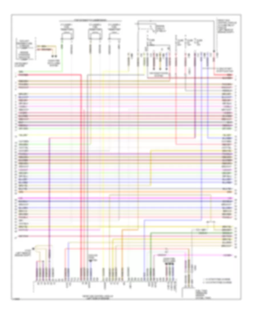
3.5L, Engine Performance Wiring Diagram (1 of 6) for Mercedes-Benz C350 2014

List of elements for 3.5L, Engine Performance Wiring Diagram (1 of 6) for Mercedes-Benz C350 2014:
- (+)
- (+) 5v
- (-)
- (on fuel rail) quantity control valve
- (top of left cylinder bank) cylinder 5 fuel injection
- (under right front seat) w19
- (w/ stratified charge) left nox sensor control unit
- A s agr2p
- A t agr2m
- C4i
- C6i
- C9g
- Computer data lines system
- Coolant thermostat heating element (top front of engine block)
- Dcm
- E f agrp1
- E f agrp2
- Engine oil pump valve
- Ev 1
- Ev2
- Ev3
- Ev5
- Front sam control module w/ fuse/ relay module (left rear of engine compt)
- Fuse 10a
- Fuse 7.5a
- Hot at all times
- Hot w/ chassis circuit 87 relay energized
- Hot w/ circuit relay energized
- Intake manifold resonance flap switch over valve
- Intake manifold selector drum switch over valve
- Ip1s
- Ip2s
- Ipm
- Left nox sensor
- Left o2 sensor downstream of catalytic converter (under left front of vehicle, in exhaust)
- Ls2hk
- Lsh1hk
- Lshk
- Lshvk1
- Me-sfi (me) control module (left side of engine)
- Nca
- Nwsa 1
- Nwsa 2
- Nwse 1
- Nwse 2
- Pnk
- Pnk/red
- Right nox sensor
- Right nox sensor control unit (w/ stratified charge)
- Right o2 sensor downstream of catalytic converter (under right front of vehicle, in exhaust)
- W19 (under right front seat)
- X86/3-c1
- X86/4-c2
- Zeu 2
- Zue 1
- Zue 3
- Zue 4
- Zue 5
- Zue 6
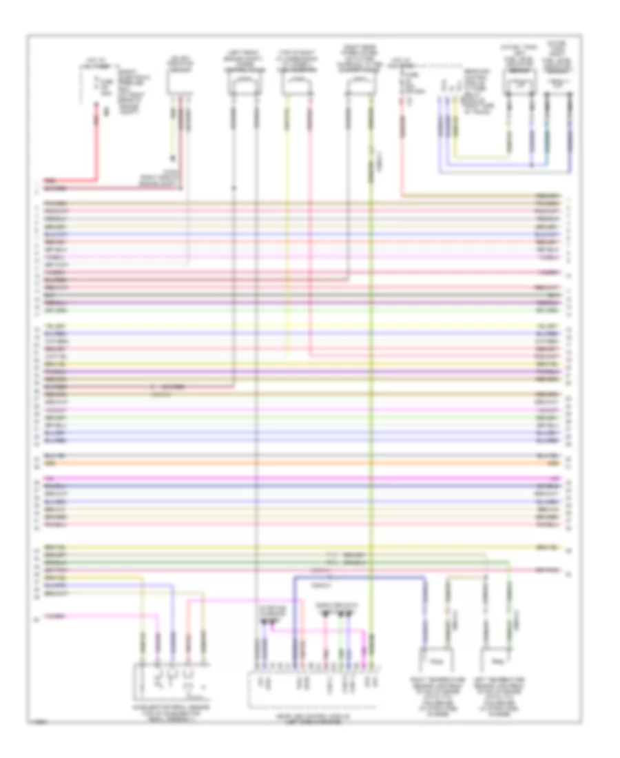
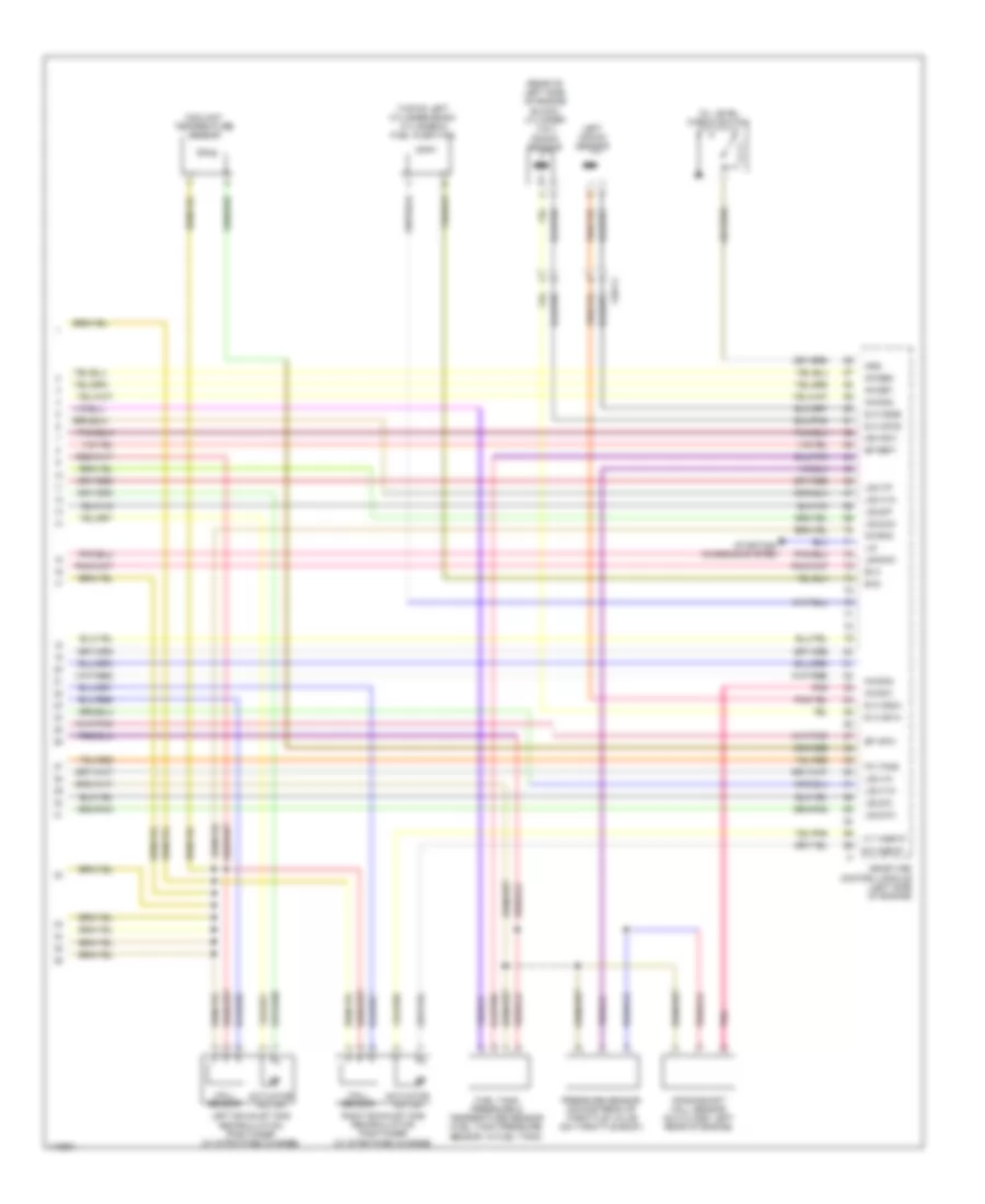
3.5L, Engine Performance Wiring Diagram (2 of 6) for Mercedes-Benz C350 2014
List of elements for 3.5L, Engine Performance Wiring Diagram (2 of 6) for Mercedes-Benz C350 2014:
- (+) 5v
- (top of right cylinder bank)
- +5v
- Air conditioning system
- C14m
- C16s
- C18m
- C20m
- C2i
- C3m
- C4i
- C6i
- Can c h
- Can e h
- Can i h
- Computer data lines system
- Coolant temperature warning lamp
- Cooling fans system
- Crash
- Cylinder 1 fuel injection
- Cylinder 2 fuel injection
- Cylinder 3 fuel injection
- Dst
- Ekpr
- Engine circuit 87 relay
- Engine diagnosis indicator lamp
- Exp
- Front sam control module w/ fuse/ relay module (left rear of engine compt)
- Fuel tank pressure sensor (in fuel tank)
- Fuse 15a
- Fuse 20a
- Instrument cluster
- Lin c1
- Me-sfi (me) control module (left side of engine)
- Pnk/red
- Red
- Sp1s
- Tag2
- W/ eco start/ stop function
- W/ stratified charge
- W/o stratified charge
- W16/5 (left rear of engine compt)
- X25/4
- X26-c1
- X35/6-c1
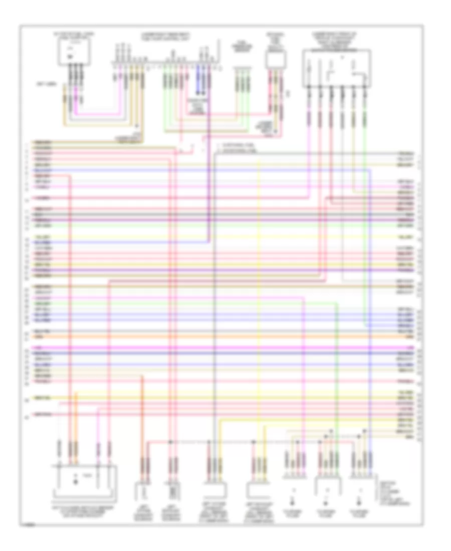
3.5L, Engine Performance Wiring Diagram (3 of 6) for Mercedes-Benz C350 2014
List of elements for 3.5L, Engine Performance Wiring Diagram (3 of 6) for Mercedes-Benz C350 2014:
- (in fuel tank) left fuel level indicator sensor
- (in fuel tank) right fuel level indicator sensor
- (left front engine compt) purge control valve
- (right rear wheelhouse) activated charcoal filter shutoff valve
- (sulev) radiator sensor
- (top of right cylinder bank) cylinder 4 fuel injection
- Aav
- Accelerator pedal sensor (top of accelerator pedal assembly)
- C3i
- C9i
- Can c l
- Can e l
- Can i l
- Computer data lines system
- Front electrical prefuse box (at right rear of engine compt)
- Fuse 150a
- Fuse 20a (or 25a)
- Hot at all times
- Left temperature sensor upstream of nox storage catalytic converter (w/ stratified charge)
- Lpv
- Me-sfi (me) control module (left side of engine)
- Mr2
- Nca
- Pnk
- Rear sam control module w/ fuse/ relay module (right side of trunk)
- Red
- Right temperature sensor upstream of nox storage catalytic converter (w/ stratified charge)
- Sp2s
- Starting/ charging system
- Str
- Str+
- Tag1
- Tg l
- Tg r
- W16/4 (right side of engine compt)
- X35/6-c1
- X86/3-c2
- X86/4-c2
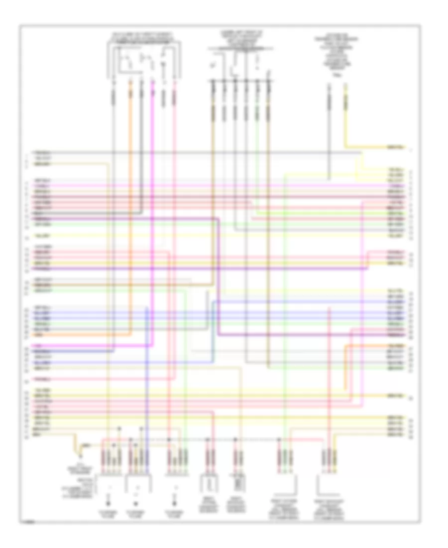
3.5L, Engine Performance Wiring Diagram (4 of 6) for Mercedes-Benz C350 2014
List of elements for 3.5L, Engine Performance Wiring Diagram (4 of 6) for Mercedes-Benz C350 2014:
- (+)
- (-)
- (ethanol fuel) fuel quality sensor
- (in top of fuel tank) fuel pump (fp)
- (not used)
- (under driver's seat) w18
- (under right front of vehicle, in exhaust) right o2 sensor (upstream of catalytic converter)
- (under right rear seat) fuel pump control unit
- Can c h
- Can c l
- Computer data lines system
- E rds
- Ekp ec u
- Ekp ec v
- Ekp ec w
- Fuel pressure sensor
- Hot film mass air flow sensor (w/ stratified charge) (on intake air duct)
- Ignition coils (cylinder 4, 5, 6: top of left cylinder bank)
- Left exhaust camshaft hall sensor (front of left cylinder bank)
- Left exhaust camshaft solenoid
- Left intake camshaft hall sensor (front of left cylinder bank)
- Left intake camshaft solenoid
- Nca
- Pnk
- To spark plugs
- W/ ethanol fuel
- W/o ethanol fuel
- W76 (under right rear seat)
- X75
3.5L, Engine Performance Wiring Diagram (5 of 6) for Mercedes-Benz C350 2014
List of elements for 3.5L, Engine Performance Wiring Diagram (5 of 6) for Mercedes-Benz C350 2014:
- (glk class: on throttle body) (c class: in air intake manifold) throttle valve actuator
- (intake air temperature sensor: part of hot film maf sensor) intake manifold & intake air temperature sensor
- (under left front of vehicle, in exhaust) left o2 sensor (upstream of catalytic converter)
- Ignition coils (cylinder 1, 2, 3: top of right cylinder bank)
- Nca
- Right exhaust camshaft hall sensor (front of right cylinder bank)
- Right exhaust camshaft solenoid
- Right intake camshaft hall sensor (front of right cylinder bank)
- Right intake camshaft solenoid
- To spark plugs
- W11 (right front of engine)
3.5L, Engine Performance Wiring Diagram (6 of 6) for Mercedes-Benz C350 2014
List of elements for 3.5L, Engine Performance Wiring Diagram (6 of 6) for Mercedes-Benz C350 2014:
- (rear of left side of engine block) cylinder 3 & 4 knock sensor
- (top of left cylinder bank) cylinder 6 fuel injection
- A t agr1p
- Actuator motor
- Coolant temperature sensor
- Crankshaft hall sensor (glk class: left rear of engine)
- E a ks1a
- E a ks1b
- E a ks2a
- E a ks2b
- E f agr1p
- Ef hfm1
- Ef ref1
- Ev4
- Ev6
- Fa tans
- Fuel tank pressure & temperature sensor (fuel tank pressure sensor: in fuel tank)
- Hall sensor
- Left exhaust gas recirculation positioner (w/ stratified charge)
- Left knock sensor
- Lin
- Lsh2hk
- Lsu1ia
- Lsu1ip
- Lsu1vm
- Lsu1vn
- Lsu2ia
- Lsu2ip
- Lsu2un
- Lsu2vm
- Me-sfi (me) control module (left side of engine)
- Mr hfm1
- Nwga1
- Nwga2
- Nwge1
- Nwge2
- Nwgm2
- Oil level check switch
- Oss
- Pnk
- Pressure sensor downstream of throttle valve (on throttle body)
- Right exhaust gas recirculation positioner (w/ stratified charge)
- Starting/ charging system
- X26-c4