ENGINE PERFORMANCE
2.0L TURBO
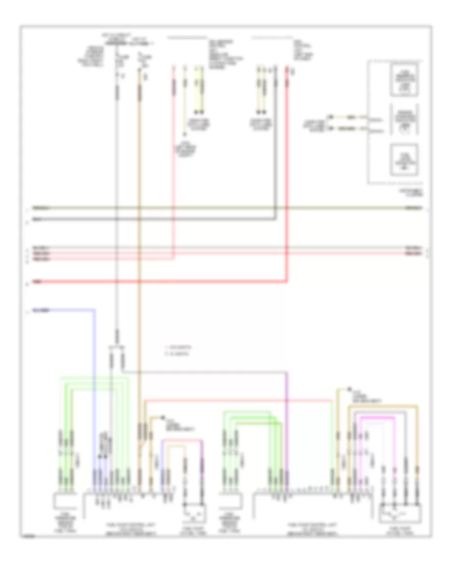
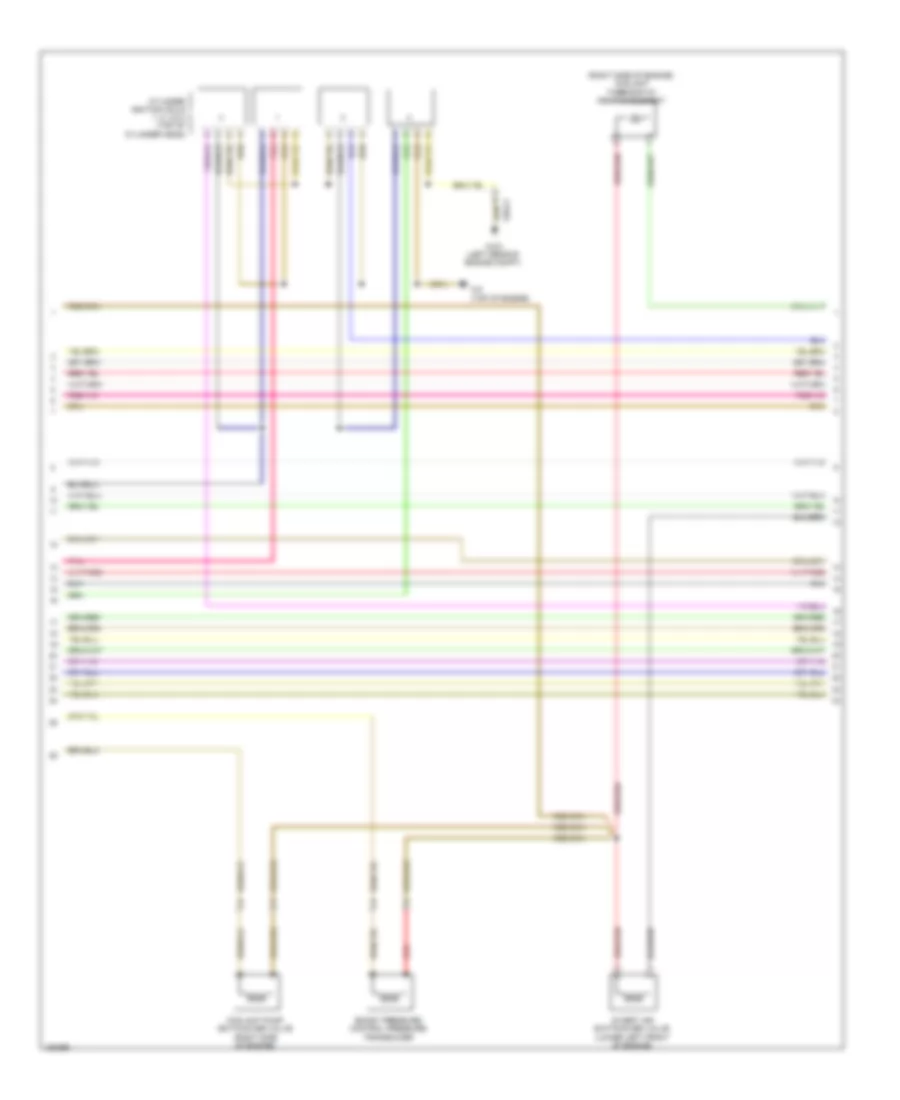
2.0L Turbo, Engine Performance Wiring Diagram (1 of 7) for Mercedes-Benz CLA250 4Matic 2014

List of elements for 2.0L Turbo, Engine Performance Wiring Diagram (1 of 7) for Mercedes-Benz CLA250 4Matic 2014:
- 30g
- 58km
- 58kn
- 58ko
- 5v +
- 87m
- Accelerator pedal sensor (top of accelerator pedal assembly)
- Activated charcoal filter shutoff valve (right of fuel tank)
- Can c h
- Can c l
- Can e h
- Can e l
- Can i h
- Can i l
- Circuit 87m relay
- Computer data lines system
- Cooling fans system
- Engine compartment fuse & relay module (left side of engine compt)
- Fan motor (behind radiator)
- Fuel tank pressure sensor (in fuel tank)
- Fuse 10a
- Fuse 15a
- Fuse 20a
- Fuse 30a
- Fuse 5a
- Gnd
- Hot at all times
- Ksp a
- Me-sfi (me) control module (left front of engine compt)
- Mr2
- Nca
- Park pawl control unit circuit 87 relay
- Purge control valve (right rear of engine)
- Pwm
- Red
- S10
- Sig
- Starting/charging system
- Str
- Temperature sensor upstream of nox storage catalytic converter (gasoline direct injection w/ stratified charge)
- Vehicle interior fuse box (right front footwell)
- W/ eco start/stop function
- W/ fan 300w & 400w
- W/ fan 600w & 850w
- W11 (left rear of engine compt)
- W3/2 (left rear of engine compt)
- Wsa
- X25/13-c1
- X25/13-c2
- X25/14-c1
- X25/18-c1
- X26-c1
- X36/2-c1
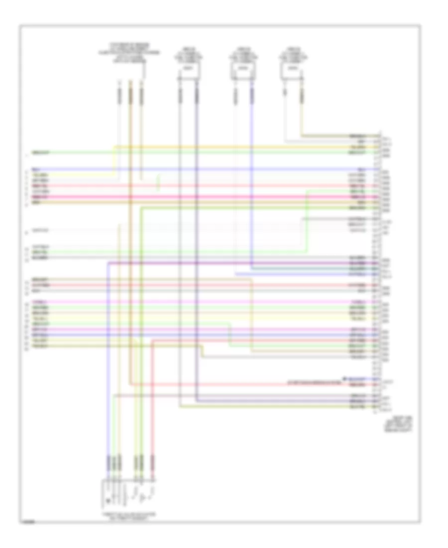
2.0L Turbo, Engine Performance Wiring Diagram (2 of 7) for Mercedes-Benz CLA250 4Matic 2014
List of elements for 2.0L Turbo, Engine Performance Wiring Diagram (2 of 7) for Mercedes-Benz CLA250 4Matic 2014:
- (+)
- 5v +
- Can b h
- Can b l
- Can c h
- Can c l
- Computer data lines system
- Engine diagnosis indicator lamp
- Fuel level indicator
- Fuel pressure sensor (top of fuel tank)
- Fuel pump (in fuel tank)
- Fuel pump control unit (w/ 4matic) (behind right rear seat)
- Fuel pump control unit (w/o 4matic) (behind right rear seat)
- Fuel reserve indicator lamp
- Fuse 25a
- Fuse 5a
- Gnd
- Hot at all times
- Hot w/ circuit 15 relay energized
- Instrument cluster
- Ksp a
- Nca
- Nox sensor control unit (gasoline direct injection w/ stratified charge)
- Pwm
- Red
- S25
- Sam control unit (left end of dash)
- Sig
- System data lines computer
- Uh2
- Vehicle interior fuse box (right front footwell)
- W/ 4matic
- W/o 4matic
- W18 (under driver's seat)
- W3/2 (left rear of engine compt)
- X36/2-c1
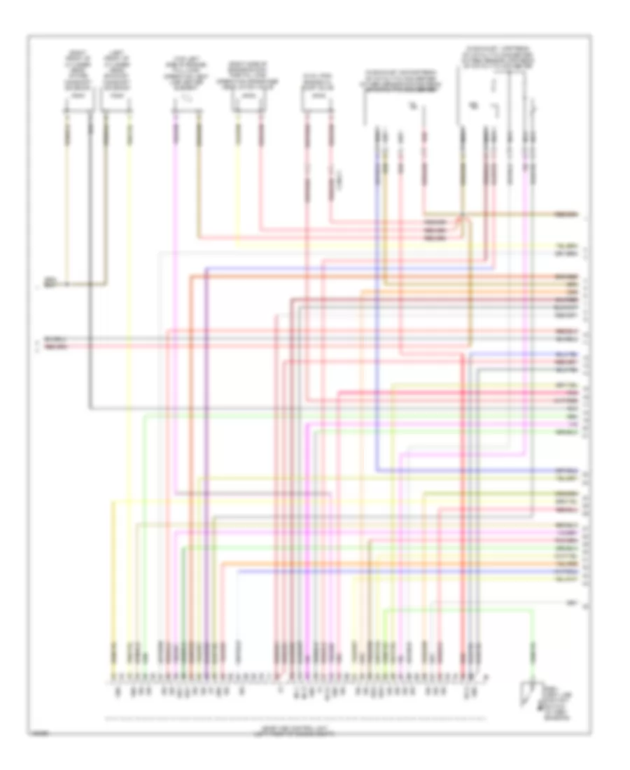
2.0L Turbo, Engine Performance Wiring Diagram (3 of 7) for Mercedes-Benz CLA250 4Matic 2014
List of elements for 2.0L Turbo, Engine Performance Wiring Diagram (3 of 7) for Mercedes-Benz CLA250 4Matic 2014:
- (+)
- (in exhaust, downstream of catalytic converter) oxygen sensor downstream of catalytic converter
- (in exhaust, upstream of catalytic converter) oxygen sensor upstream of catalytic converter
- (in oil pan) engine oil pump valve
- (left front of cylinder head) exhaust camshaft solenoid
- (right front of cylinder head) intake camshaft solenoid
- (right side of engine block) partial load operation crankcase ventilation valve
- (top left side of engine) full-load operation vent line heater element
- Gnd
- He (+)
- He (-)
- Inj h
- Inj l
- Me-sfi (me) control unit (left front of engine compt)
- Nca
- Pnk
- Pzev vent line contact switch (w/ pzev emission)
- Red
- Sig
- Sig1
- Sig2
- X130-c1
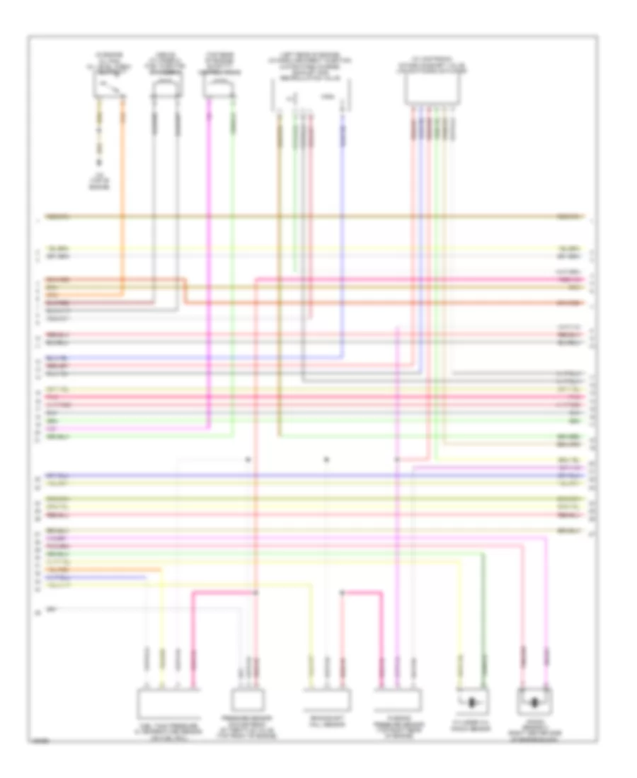
2.0L Turbo, Engine Performance Wiring Diagram (4 of 7) for Mercedes-Benz CLA250 4Matic 2014
List of elements for 2.0L Turbo, Engine Performance Wiring Diagram (4 of 7) for Mercedes-Benz CLA250 4Matic 2014:
- (above cylinder 2) fuel injector cylinder 2
- (in engine oil pan) oil level check switch
- (left rear of engine) (w/ gasoline direct injection & stratified charge) exhaust gas recirculation valve
- (top rear of engine) quantity control valve
- (w/ camtronic) intake camshaft valve lift switching actuator
- Crankshaft hall sensor
- Cylinder 3+4 knock sensor
- Fuel tank pressure & temperature sensor (on fuel rail)
- Knock sensor 2 (right center side of engine block)
- Pnk
- Pressure sensor downstream of throttle valve (top front of engine)
- Purging pressure sensor (top right rear of engine)
- W2 (top of engine)
2.0L Turbo, Engine Performance Wiring Diagram (5 of 7) for Mercedes-Benz CLA250 4Matic 2014
List of elements for 2.0L Turbo, Engine Performance Wiring Diagram (5 of 7) for Mercedes-Benz CLA250 4Matic 2014:
- (right side of engine) coolant temperature sensor
- (top center rear of engine) charge air temperature sensor upstream of throttle valve
- (top of engine) charge air temperature sensor downstream of throttle valve
- Exhaust camshaft hall sensor (left front of cylinder head)
- Exhaust gas recirculation pressure sensor 1 (w/ gasoline direct injection & stratified charge) (left rear of engine)
- Exhaust gas recirculation pressure sensor 2 (w/ gasoline direct injection & stratified charge) (left rear of engine)
- Intake camshaft hall sensor (right front of cylinder head)
- Pnk
- Pressure sensor downstream of air filter (on air intake duct)
- Pressure sensor upstream of throttle valve (top center rear of engine)
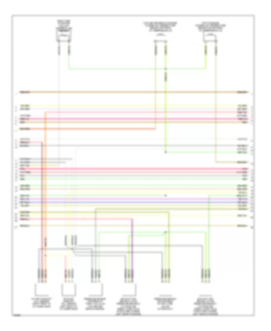
2.0L Turbo, Engine Performance Wiring Diagram (6 of 7) for Mercedes-Benz CLA250 4Matic 2014
List of elements for 2.0L Turbo, Engine Performance Wiring Diagram (6 of 7) for Mercedes-Benz CLA250 4Matic 2014:
- (right side of engine) coolant thermostat heating element
- Boost pressure control pressure transducer
- Coolant pump switchover valve (right side of engine)
- Cylinder ignition coils 1, 2, 3 & 4 (top of cylinder head)
- Divert air switchover valve (lower left front of engine)
- Pnk
- Red
- W2 (top of engine)
- W3/2 (left rear of engine compt)
- X26-c1
2.0L Turbo, Engine Performance Wiring Diagram (7 of 7) for Mercedes-Benz CLA250 4Matic 2014
List of elements for 2.0L Turbo, Engine Performance Wiring Diagram (7 of 7) for Mercedes-Benz CLA250 4Matic 2014:
- (+)
- (+) 5v
- (above cylinder 1) fuel injector cylinder 1
- (above cylinder 3) fuel injector cylinder 3
- (above cylinder 4) fuel injector cylinder 4
- (top rear of engine) (w/ gasoline direct injection & stratified charge) hot film mass air flow sensor
- +5v
- Gnd
- Inj h
- Inj l
- Lin c1
- Me-sfi (me) control unit (left front of engine compt)
- Mot
- Sig
- Starting/charging system
- Throttle valve actuator (on throttle body)