ENGINE PERFORMANCE
3.0L TURBO DIESEL
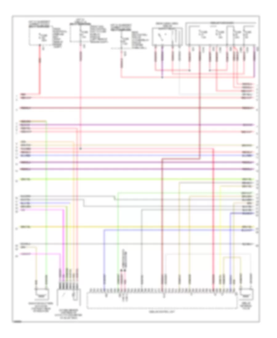
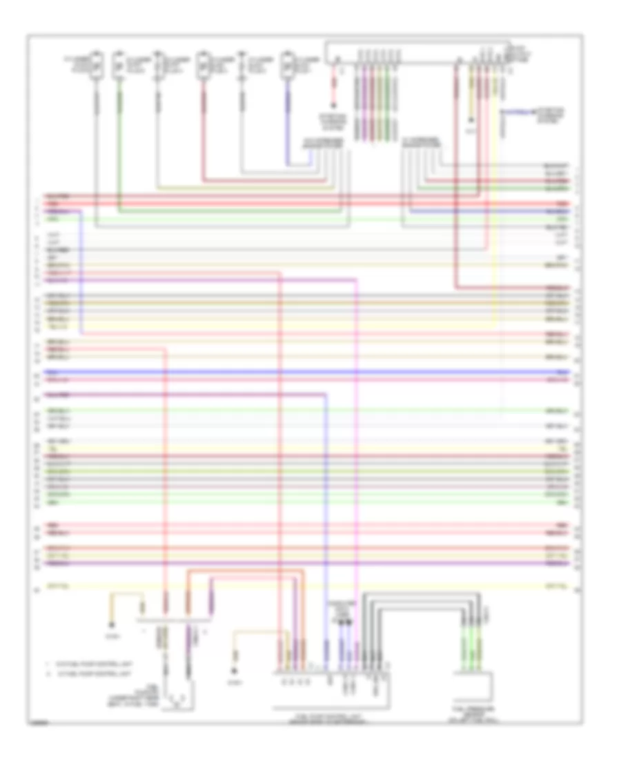
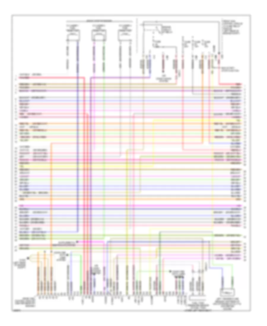
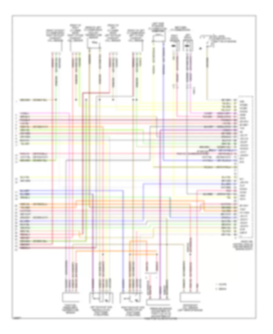
3.0L Turbo Diesel, Engine Performance Wiring Diagram (1 of 8) for Mercedes-Benz E350 2012

List of elements for 3.0L Turbo Diesel, Engine Performance Wiring Diagram (1 of 8) for Mercedes-Benz E350 2012:
- (+)
- (-)
- 30g
- 87m
- Accelerator pedal sensor (on accelerator pedal assembly)
- Air conditioning system
- C16s
- C1v
- C3i
- C3m
- C4i
- C6i
- C9i
- Can-c h
- Can-c l
- Can-e h
- Can-e l
- Can-i h
- Can-i l
- Cdi control module (right rear of engine compt)
- Computer data lines system
- Control unit
- Crash
- Differential pressure sensor/diesel particulate filter for onboard diagnostics (obd)
- Ekp
- Engine circuit relay
- Front electrical prefuse box (right rear of engine compt)
- Front sam sam control module w/ fuse/relay module (left rear of engine compt)
- Fuel pump relay
- Fuse 150a mr7
- Fuse 15a
- Fuse 20a
- Fuse 25a
- Fuse 7.5a
- Hot at all times
- Hot w/ chassis circuit 87 relay energized
- Left fuel level indicator sensor (in fuel tank, under left rear seat)
- Lscp1
- Lsh1
- Lsvg1
- Lsvn1
- Lues
- Nca
- Pnk
- Pnk/red
- Rear sam control unit w/ fuse & relay module (in spare wheelwell)
- Red
- Right fuel level indicator sensor (in fuel tank, under right rear seat)
- Shut
- Sig
- Sp1m
- Sp1s
- Sp2m
- Sp2s
- Starting/charging system
- Str
- Temperature sensor upstream of diesel particulate filter
- Temperature sensor upstream of scr catalytic converter
- Tg l
- Tg r
- U pwg
- W/ fuel system
- W/o fuel system control unit
- W16/6 (right rear of engine compt)
- X26
- X26-c1
- X36/2-c1
- X36/3-c1
- X86/1-c1b
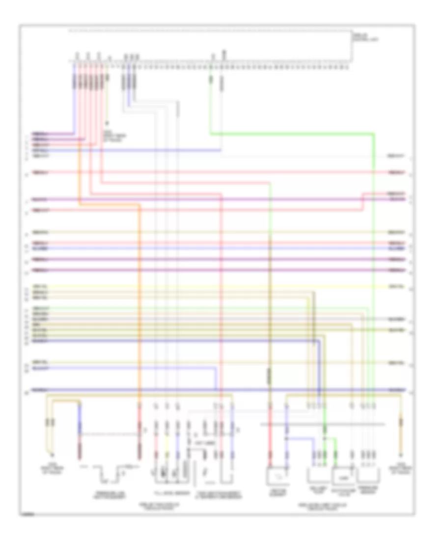
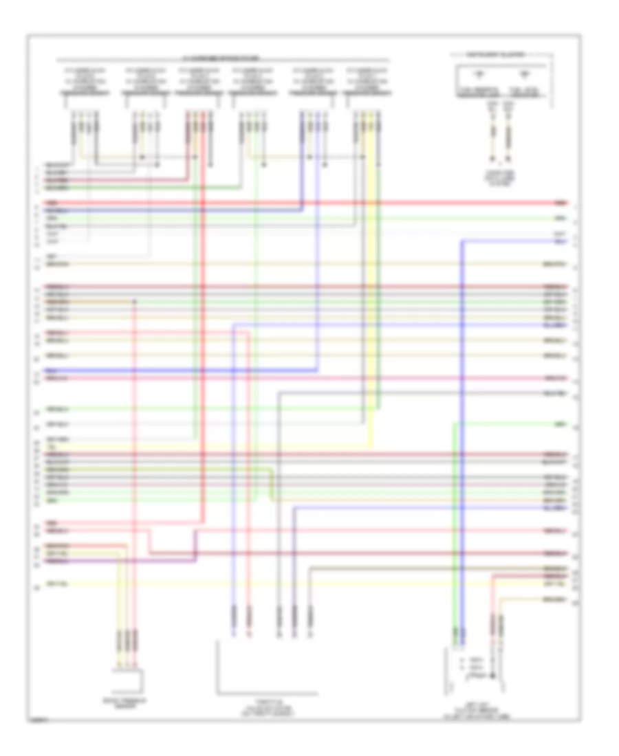
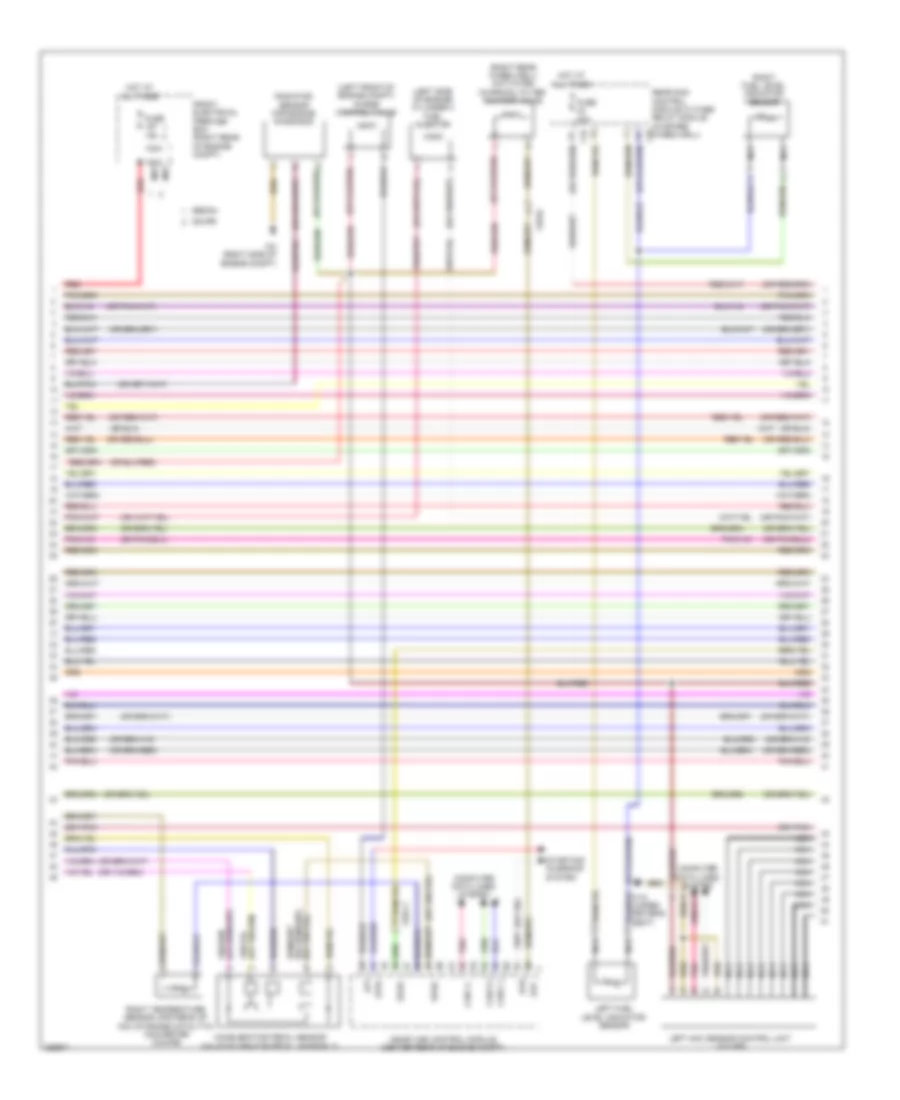
3.0L Turbo Diesel, Engine Performance Wiring Diagram (2 of 8) for Mercedes-Benz E350 2012
List of elements for 3.0L Turbo Diesel, Engine Performance Wiring Diagram (2 of 8) for Mercedes-Benz E350 2012:
- (-)
- 15 r
- C19a
- C20a
- C21a
- C22a
- C6i
- Can i h
- Can i l
- E19
- E20
- E21
- E22
- Front electrical prefuse box (right rear of engine compt)
- Front sam sam control unit w/ fuse & relay module (left rear of engine compt)
- Fuse 10a
- Fuse 150a
- Fuse 15a
- Fuse 20a
- Fuse 5a
- Fuse 7.5a
- Hot w/ circuit 15 relay energized
- Hot w/ quiescent current cutout relay energized
- Ig1
- Lines system computer data
- Nca
- Pnk
- Pnk/red
- Radiator shutters actuator (top right rear of radiator)
- Rear sam control module w/ fuse/relay module (in spare wheelwell)
- Red
- Scr
- Sig
3.0L Turbo Diesel, Engine Performance Wiring Diagram (3 of 8) for Mercedes-Benz E350 2012
List of elements for 3.0L Turbo Diesel, Engine Performance Wiring Diagram (3 of 8) for Mercedes-Benz E350 2012:
- (not used)
- +5v
- 15 r
- Delivery pump
- Empty
- Fill level sensor
- Full
- Heating element
- Pressure line heating element
- Pressure sensor
- Red
- Reserve
- Sig
- Sp2m
- Switchover valve
- Tank heating element & temperature sensor
- W8/8 (right rear of trunk)
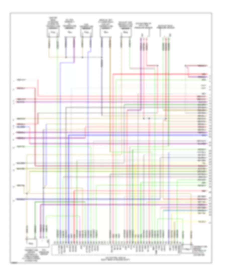
3.0L Turbo Diesel, Engine Performance Wiring Diagram (4 of 8) for Mercedes-Benz E350 2012
List of elements for 3.0L Turbo Diesel, Engine Performance Wiring Diagram (4 of 8) for Mercedes-Benz E350 2012:
- (+)
- (-)
- (center rear of engine) charge air temperature sensor
- (oil pan assembly) oil temperature sensor
- (rear of left cylinder bank) coolant temperature sensor
- A-ldr
- A-zme
- Br-ds1
- Br-ds2
- Br-ds3
- Br-ds4
- Br-ds5
- Br-ds6
- Cdi control module (right rear of engine compt)
- Downstream of air filter pressure sensor
- E-p3
- Ea lds
- Erg sig
- Exhaust back pressure sensor
- Exhaust gas recirculation temperature sensor
- Exts2
- Fuel temperature sensor
- Gnd
- Ia tegr
- Inj h
- Kts sig
- Lin c1
- Ll tf sig
- Lsca1
- Lscp1
- Lsh1
- Lsvg1
- Lsvn1
- Oeltemp
- Rail pressure sensor
- Rds
- Red
- Sig
- Sig-kas
- T-sig
- Temp agr
- Temperature sensor upstream of catalytic converter
- Temperature sensor upstream of turbocharger (in turbocharger charge pipe)
- Tmot
3.0L Turbo Diesel, Engine Performance Wiring Diagram (5 of 8) for Mercedes-Benz E350 2012
List of elements for 3.0L Turbo Diesel, Engine Performance Wiring Diagram (5 of 8) for Mercedes-Benz E350 2012:
- (right rear of engine) differential pressure sensor (dpf)
- Condensation sensor for fuel filter w/ heating element
- Nca
- Pressure regulator valve
- Quantity control valve
- Red
- Sig
- W11
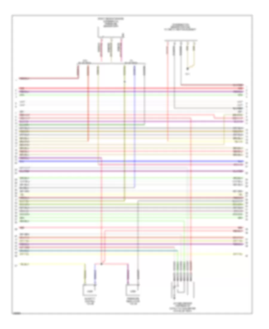
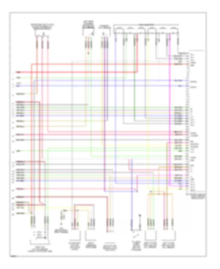
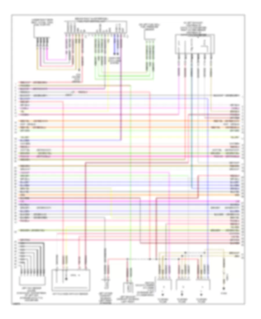
3.0L Turbo Diesel, Engine Performance Wiring Diagram (6 of 8) for Mercedes-Benz E350 2012
List of elements for 3.0L Turbo Diesel, Engine Performance Wiring Diagram (6 of 8) for Mercedes-Benz E350 2012:
- (+)
- (-)
- 1 zyl
- 2 zyl
- 3 zyl
- 4 zyl
- 5 zyl
- 6 zyl
- Can-c h
- Can-c l
- Computer data lines system
- Cylinder glow plug 1
- Cylinder glow plug 2
- Cylinder glow plug 3
- Cylinder glow plug 4
- Cylinder glow plug 5
- Cylinder glow plug 6
- Ekp
- Fuel pressure sensor (on left fuel rail)
- Fuel pump (fp) (under right rear seat, in fuel tank)
- Fuel pump control unit (behind right quarterpanel)
- Glow output stage
- Htr 1
- Htr 2
- Kds_sig
- Lin c1
- Nca
- Red
- Sig
- Starting/ charging system
- W/ fuel pump control unit
- W/ increased engine power
- W/o fuel pump control unit
- W/o increased engine power
- W11
- W15/1
- X26-c3
- X36/2-c1
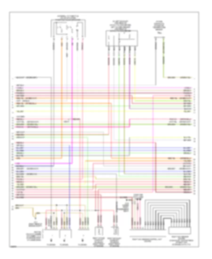
3.0L Turbo Diesel, Engine Performance Wiring Diagram (7 of 8) for Mercedes-Benz E350 2012
List of elements for 3.0L Turbo Diesel, Engine Performance Wiring Diagram (7 of 8) for Mercedes-Benz E350 2012:
- Boost pressur sensor
- Can- b h
- Can- b l
- Computer data lines system
- Cylinder glow plug 1 w/ combustion chamber pressure sensor
- Cylinder glow plug 2 w/ combustion chamber pressure sensor
- Cylinder glow plug 3 w/ combustion chamber pressure sensor
- Cylinder glow plug 4 w/ combustion chamber pressure sensor
- Cylinder glow plug 5 w/ combustion chamber pressure sensor
- Cylinder glow plug 6 w/ combustion chamber pressure sensor
- Fuel level indicator
- Fuel reserve indicator lamp
- Instrument cluster
- Left hot film maf sensor (in left air intake tube)
- Red
- Throttle valve actuator (on throttle body)
- W/ increased engine power
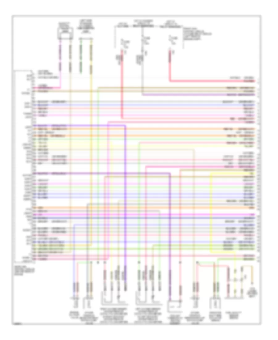
3.0L Turbo Diesel, Engine Performance Wiring Diagram (8 of 8) for Mercedes-Benz E350 2012
List of elements for 3.0L Turbo Diesel, Engine Performance Wiring Diagram (8 of 8) for Mercedes-Benz E350 2012:
- (+)
- (-)
- (left rear of engine) crankshaft hall sensor
- A-eka
- Boost pressure positioner
- Camshaft hall sensor
- Cdi control module (right rear of engine compt)
- Crankcase ventilation system differential pressure sensor
- Drv
- E-hfm1
- E-hfm2
- Exhaust gas recirculation actuator
- Fuel injectors
- Gnd
- Ia pfdpt
- Inj h
- Inj l
- Intake port shutoff actuator motor
- Kg-sig
- Kwga
- Left intake port shutoff hall sensor
- M (+)
- M (-)
- Nca
- Nwg-sig
- Oil level check switch (bottom of engine)
- Oss
- Red
- Right hot film maf sensor (in right air intake tube)
- Right intake port shutoff hall sensor
- Sig
- Sig-kas-l
- T1-1
- T1-2
- W3/1 (behind right front fender)
- X26-c1
3.5L
3.5L, Engine Performance Wiring Diagram (1 of 6) for Mercedes-Benz E350 2012
List of elements for 3.5L, Engine Performance Wiring Diagram (1 of 6) for Mercedes-Benz E350 2012:
- (+)
- (-)
- (left side of engine) cylinder 5 fuel injector
- +5v
- Agap1
- Agr2p
- Agrp2
- C4i
- C6i
- C9g
- Catalytic converter)
- Coolant thermostat heating element
- Dcm
- Dcp
- Engine oil pump valve
- Ev1
- Ev2
- Ev3
- Ev4
- Ev5
- Front sam control module w/ fuse/ relay module (left rear of engine compt)
- Fuel quality sensor (sedan)
- Fuse 10a
- Fuse 7.5a
- Hot at all times
- Hot w/ chassis circuit 15 relay energized
- Hot w/ circuit 15 relay energized
- Intake manifold resonance flap switch over valve
- Intake manifold selector drum switch over valve
- Ip1s
- Ip2s
- Ipm
- Kwths
- Left oxygen sensor downstream of catalytic converter (in left exhaust, downstream of
- Lhs1hk
- Lhsvk1
- Ls2hk
- Lshk
- Me-sfi (me) control module (center rear of engine)
- Nca
- Nwas2
- Nwsa1
- Nwse 1
- Pnk/red
- Quantity control valve
- Radiator shutters actuator (sedan)
- Red
- Right oxygen sensor downstream of catalytic converter (in right exhaust, downstream of
- Su2
- Tanss
- W18 (under driver's seat)
- X75
- Zue 1
- Zue 4
- Zue 5
- Zue 6
- Zue2
3.5L, Engine Performance Wiring Diagram (2 of 6) for Mercedes-Benz E350 2012
List of elements for 3.5L, Engine Performance Wiring Diagram (2 of 6) for Mercedes-Benz E350 2012:
- (right side of engine)
- +5v
- A-a-sam
- Air
- Air cond- itioning system
- Askj
- C18m
- C3m
- C4i
- C4m
- C6i
- C8s
- Can c h
- Can e h
- Can i h
- Can l h
- Can l l
- Computer data lines system
- Conditioning system
- Crash
- Cylinder 1 fuel injection
- Cylinder 2 fuel injection
- Cylinder 3 fuel injection
- Eco start/ stop function
- Ekpr
- Engine circuit 87 relay
- Front sam control module w/ fuse/ relay module (left rear of engine compt)
- Fuel tank pressure sensor (in fuel tank, under left rear seat)
- Fuse 15a
- Fuse 20a
- Kup1
- Left temperature sensor upstream of nox storage catalytic converter (coupe)
- Lin c1
- Me-sfi (me) control module (center rear of engine)
- Pnk/red
- Red
- S-sam
- Sp1s
- U pwg1
- W16/5 (left rear of engine compt)
- X25/4-c1
- X26-c1
3.5L, Engine Performance Wiring Diagram (3 of 6) for Mercedes-Benz E350 2012
List of elements for 3.5L, Engine Performance Wiring Diagram (3 of 6) for Mercedes-Benz E350 2012:
- (left front of engine compt) purge control valve
- (left side of engine) cylinder 4 fuel injector
- (right rear wheelwell) activated charcoal filter shutoff valve
- 100a
- 150a mr7
- Aav
- Accelerator pedal sensor (on accelerator pedal assembly)
- C3i
- C9i
- Can c l
- Can e l
- Can i l
- Computer data lines system
- Coupe
- Front electrical prefuse box (right rear of engine compt)
- Fuse
- Fuse 20a
- Hot at all times
- Left fuel level indicator sensor
- Left nox sensor control unit (coupe)
- Lpv
- Me-sfi (me) control module (center rear of engine compt)
- Mr2
- Nca
- Pnk
- Radiator sensor for engine diagnosis
- Rear sam control module w/ fuse/ relay module (in spare wheelwell)
- Red
- Right fuel level indicator sensor
- Right temperature sensor upstream of nox storage catalytic converter (coupe)
- Sedan
- Sp2s
- Starting/ charging system
- Str
- Str+
- W2 (right side of engine compt)
- X26-c1
- X3516
- X86/3-c1
3.5L, Engine Performance Wiring Diagram (4 of 6) for Mercedes-Benz E350 2012
List of elements for 3.5L, Engine Performance Wiring Diagram (4 of 6) for Mercedes-Benz E350 2012:
- (+)
- (-)
- (behind right quarterpanel) fuel pump control unit
- (in left exhaust, upstream of catalytic converter) right oxygen sensor upstream of catalytic converter
- (on left fuel rail) fuel pressure sensor
- (under right rear seat, in fuel tank) fuel pump (fp)
- Can c h
- Can c l
- Computer data lines system
- Ekp
- Gnd
- Hot film mass air flow sensor
- Ignition coils cylinders (cylinder 4, 5, 6: on engine left cylinder bank)
- Kds sig
- Kos
- Left exhaust camshaft solenoid (left front
- Left intake camshaft solenoid (left front of engine)
- Left nox sensor (coupe) (in exhaust, downstream of left nox storage catalytic converter)
- Nca
- Phase u
- Phase v
- Phase w
- To spark plugs
- W16/5
- W76 (coupe) w15/1 (sedan)
- X26-c1
3.5L, Engine Performance Wiring Diagram (5 of 6) for Mercedes-Benz E350 2012
List of elements for 3.5L, Engine Performance Wiring Diagram (5 of 6) for Mercedes-Benz E350 2012:
- (coupe) (in exhaust, downstream of right nox storage catalytic
- (in left exhaust, upstream of catalytic converter) left oxygen sensor upstream of catalytic converter
- (integral to throttle valve actuator) throttle valve actuator
- Computer data lines system
- Ignition coils cylinders (cylinder 1, 2, 3: on engine right cylinder bank)
- Intake manifold & intake air temperature sensor
- Nca
- Pnk
- Right exhaust camshaft solenoid (right front of engine)
- Right intake camshaft solenoid (right front of engine)
- Right nox sensor
- Right nox sensor control unit (coupe)
- To spark
- W11 (right rear of engine compt)
- W19 (under front passenger's seat)
- X26-c1
- X86/4-c2
3.5L, Engine Performance Wiring Diagram (6 of 6) for Mercedes-Benz E350 2012
List of elements for 3.5L, Engine Performance Wiring Diagram (6 of 6) for Mercedes-Benz E350 2012:
- (-)
- (between cylinder banks)
- (front of left cylinder bank) left exhaust camshaft hall sensor
- (front of left cylinder bank) left intake camshaft hall sensor
- (front of right cylinder bank) right exhaust camshaft hall sensor
- (front of right cylinder bank) right intake camshaft hall sensor
- (left side of engine) cylinder 6 fuel injectior
- (rear of left cylinder bank) coolant temperature sensor
- Agr1p
- Coupe
- Crankshaft hall sensor (left rear of engine)
- Ef hfm1
- Ef ref1
- Ev4
- Ev6
- Fa tans
- Ks1a
- Ks1b
- Ks2a
- Ks2b
- Kwga
- Kwr
- Left exhaust gas recirculation positioner (if equipped)
- Left knock sensor
- Lin c1
- Lsh2hk
- Lshvk2
- Lsu1ia
- Lsu1ip
- Lsu1um
- Lsu2ia
- Lsu2ip
- Lsu2um
- Lsu2vm
- Lsumv1
- Me-sfi (me) control module (center rear of engine compt)
- Mr hfm1
- Nwg-m2
- Nwga1
- Nwga2
- Nwge1
- Nwge2
- Oil level check switch (bottom of engine)
- Oilp
- Oss
- Pnk
- Pressure sensor downstream of throttle valve (downstream of throttle valve actuator)
- Right exhaust gas recirculation positioner (if equipped)
- Right knock sensor
- Sedan
- Starting/ charging system
- Su1
- Tank fuel pressure & temperature sensor
- Tks
- Tmdt
- X26-c4
3.5L FLEX FUEL
3.5L Flex Fuel, Engine Performance Wiring Diagram (1 of 6) for Mercedes-Benz E350 2012
List of elements for 3.5L Flex Fuel, Engine Performance Wiring Diagram (1 of 6) for Mercedes-Benz E350 2012:
- (+)
- (-)
- (left side of engine) cylinder 5 fuel injector
- +5v
- Agap1
- Agr2p
- Agrp2
- C4i
- C6i
- C9g
- Catalytic converter)
- Coolant thermostat heating element
- Dcm
- Dcp
- Engine oil pump valve
- Ev1
- Ev2
- Ev3
- Ev4
- Ev5
- Front sam control module w/ fuse/ relay module (left rear of engine compt)
- Fuel quality sensor (sedan)
- Fuse 10a
- Fuse 7.5a
- Hot at all times
- Hot w/ chassis circuit 15 relay energized
- Hot w/ circuit 15 relay energized
- Intake manifold resonance flap switch over valve
- Intake manifold selector drum switch over valve
- Ip1s
- Ip2s
- Ipm
- Kwths
- Left oxygen sensor downstream of catalytic converter (in left exhaust, downstream of
- Lhs1hk
- Lhsvk1
- Ls2hk
- Lshk
- Me-sfi (me) control module (center rear of engine)
- Nca
- Nwas2
- Nwsa1
- Nwse 1
- Pnk/red
- Quantity control valve
- Radiator shutters actuator (sedan)
- Red
- Right oxygen sensor downstream of catalytic converter (in right exhaust, downstream of
- Su2
- Tanss
- W18 (under driver's seat)
- X75
- Zue 1
- Zue 4
- Zue 5
- Zue 6
- Zue2
3.5L Flex Fuel, Engine Performance Wiring Diagram (2 of 6) for Mercedes-Benz E350 2012
List of elements for 3.5L Flex Fuel, Engine Performance Wiring Diagram (2 of 6) for Mercedes-Benz E350 2012:
- (right side of engine)
- +5v
- A-a-sam
- Air
- Air cond- itioning system
- Askj
- C18m
- C3m
- C4i
- C4m
- C6i
- C8s
- Can c h
- Can e h
- Can i h
- Can l h
- Can l l
- Computer data lines system
- Conditioning system
- Crash
- Cylinder 1 fuel injection
- Cylinder 2 fuel injection
- Cylinder 3 fuel injection
- Eco start/ stop function
- Ekpr
- Engine circuit 87 relay
- Front sam control module w/ fuse/ relay module (left rear of engine compt)
- Fuel tank pressure sensor (in fuel tank, under left rear seat)
- Fuse 15a
- Fuse 20a
- Kup1
- Left temperature sensor upstream of nox storage catalytic converter (coupe)
- Lin c1
- Me-sfi (me) control module (center rear of engine)
- Pnk/red
- Red
- S-sam
- Sp1s
- U pwg1
- W16/5 (left rear of engine compt)
- X25/4-c1
- X26-c1
3.5L Flex Fuel, Engine Performance Wiring Diagram (3 of 6) for Mercedes-Benz E350 2012
List of elements for 3.5L Flex Fuel, Engine Performance Wiring Diagram (3 of 6) for Mercedes-Benz E350 2012:
- (left front of engine compt) purge control valve
- (left side of engine) cylinder 4 fuel injector
- (right rear wheelwell) activated charcoal filter shutoff valve
- 100a
- 150a mr7
- Aav
- Accelerator pedal sensor (on accelerator pedal assembly)
- C3i
- C9i
- Can c l
- Can e l
- Can i l
- Computer data lines system
- Coupe
- Front electrical prefuse box (right rear of engine compt)
- Fuse
- Fuse 20a
- Hot at all times
- Left fuel level indicator sensor
- Left nox sensor control unit (coupe)
- Lpv
- Me-sfi (me) control module (center rear of engine compt)
- Mr2
- Nca
- Pnk
- Radiator sensor for engine diagnosis
- Rear sam control module w/ fuse/ relay module (in spare wheelwell)
- Red
- Right fuel level indicator sensor
- Right temperature sensor upstream of nox storage catalytic converter (coupe)
- Sedan
- Sp2s
- Starting/ charging system
- Str
- Str+
- W2 (right side of engine compt)
- X26-c1
- X3516
- X86/3-c1
3.5L Flex Fuel, Engine Performance Wiring Diagram (4 of 6) for Mercedes-Benz E350 2012
List of elements for 3.5L Flex Fuel, Engine Performance Wiring Diagram (4 of 6) for Mercedes-Benz E350 2012:
- (+)
- (-)
- (behind right quarterpanel) fuel pump control unit
- (in left exhaust, upstream of catalytic converter) right oxygen sensor upstream of catalytic converter
- (on left fuel rail) fuel pressure sensor
- (under right rear seat, in fuel tank) fuel pump (fp)
- Can c h
- Can c l
- Computer data lines system
- Ekp
- Gnd
- Hot film mass air flow sensor
- Ignition coils cylinders (cylinder 4, 5, 6: on engine left cylinder bank)
- Kds sig
- Kos
- Left exhaust camshaft solenoid (left front
- Left intake camshaft solenoid (left front of engine)
- Left nox sensor (coupe) (in exhaust, downstream of left nox storage catalytic converter)
- Nca
- Phase u
- Phase v
- Phase w
- To spark plugs
- W16/5
- W76 (coupe) w15/1 (sedan)
- X26-c1
3.5L Flex Fuel, Engine Performance Wiring Diagram (5 of 6) for Mercedes-Benz E350 2012
List of elements for 3.5L Flex Fuel, Engine Performance Wiring Diagram (5 of 6) for Mercedes-Benz E350 2012:
- (coupe) (in exhaust, downstream of right nox storage catalytic
- (in left exhaust, upstream of catalytic converter) left oxygen sensor upstream of catalytic converter
- (integral to throttle valve actuator) throttle valve actuator
- Computer data lines system
- Ignition coils cylinders (cylinder 1, 2, 3: on engine right cylinder bank)
- Intake manifold & intake air temperature sensor
- Nca
- Pnk
- Right exhaust camshaft solenoid (right front of engine)
- Right intake camshaft solenoid (right front of engine)
- Right nox sensor
- Right nox sensor control unit (coupe)
- To spark
- W11 (right rear of engine compt)
- W19 (under front passenger's seat)
- X26-c1
- X86/4-c2
3.5L Flex Fuel, Engine Performance Wiring Diagram (6 of 6) for Mercedes-Benz E350 2012
List of elements for 3.5L Flex Fuel, Engine Performance Wiring Diagram (6 of 6) for Mercedes-Benz E350 2012:
- (-)
- (between cylinder banks)
- (front of left cylinder bank) left exhaust camshaft hall sensor
- (front of left cylinder bank) left intake camshaft hall sensor
- (front of right cylinder bank) right exhaust camshaft hall sensor
- (front of right cylinder bank) right intake camshaft hall sensor
- (left side of engine) cylinder 6 fuel injectior
- (rear of left cylinder bank) coolant temperature sensor
- Agr1p
- Coupe
- Crankshaft hall sensor (left rear of engine)
- Ef hfm1
- Ef ref1
- Ev4
- Ev6
- Fa tans
- Ks1a
- Ks1b
- Ks2a
- Ks2b
- Kwga
- Kwr
- Left exhaust gas recirculation positioner (if equipped)
- Left knock sensor
- Lin c1
- Lsh2hk
- Lshvk2
- Lsu1ia
- Lsu1ip
- Lsu1um
- Lsu2ia
- Lsu2ip
- Lsu2um
- Lsu2vm
- Lsumv1
- Me-sfi (me) control module (center rear of engine compt)
- Mr hfm1
- Nwg-m2
- Nwga1
- Nwga2
- Nwge1
- Nwge2
- Oil level check switch (bottom of engine)
- Oilp
- Oss
- Pnk
- Pressure sensor downstream of throttle valve (downstream of throttle valve actuator)
- Right exhaust gas recirculation positioner (if equipped)
- Right knock sensor
- Sedan
- Starting/ charging system
- Su1
- Tank fuel pressure & temperature sensor
- Tks
- Tmdt
- X26-c4