ENGINE PERFORMANCE
5.0L
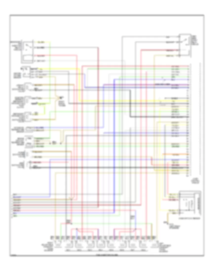
5.0L, Engine Performance Wiring Diagrams (1 of 2) for Mercedes-Benz E500 1994

List of elements for 5.0L, Engine Performance Wiring Diagrams (1 of 2) for Mercedes-Benz E500 1994:
- "b" engagement
- (behind i/p)
- (module
- (right
- Accy
- Back- up lamps
- Base module
- Battery (+)
- Block
- Brake lamp switch
- Camshaft position sensor
- Coil wire
- Computer data lines
- Crankshaft position sensor
- Data link connector
- Di control module
- Diagnostic module (pin 4)
- Ea/cc/isc control module
- Fp relay module
- Fuel pump
- Fuse 16a
- Fuse 8a
- Fuse 9 8a
- Fuse/ relay box
- G100 (left front wheel well)
- G103 box bracket)
- G103 shock tower)
- G206
- G302 (under console)
- Hot at all times
- Ignition coil 1 (right bank)
- Ignition coil 2 (left bank)
- Ignition switch
- Kickdown switch
- Kickdown valve
- Knock sensor 1 (right)
- Knock sensor 2 (left)
- Lh distributor
- Lh-sfi control module
- Lock
- Nca
- Overload protection
- Pnk/ red
- Pnk/red
- Red
- Reference
- Resistor (di)
- Rh distributor
- Run
- Shield
- Shield s
- Spark plugs
- Start
- Starter lock-out/ backup lamp switch
- Starter lock-out/ relay module
- Starting system (starter)
- Switch
- Tachometer
- Terminal
- Transmission
- Wiper/ washers system
5.0L, Engine Performance Wiring Diagrams (2 of 2) for Mercedes-Benz E500 1994
List of elements for 5.0L, Engine Performance Wiring Diagrams (2 of 2) for Mercedes-Benz E500 1994:
- (right shock tower)
- Coolant
- Egr
- Electro- magnetic secondary air injection pump clutch
- Engine
- First gear start relay module
- Fuel injection valves
- G103
- G110 (left front of engine)
- Heated oxygen sensor
- Intake air
- Left adjustable camshaft timing solenoid
- Lh-sfi control module
- Mass air flow sensor
- Nca
- No.1
- No.2
- No.3
- No.4
- No.5
- No.6
- No.7
- No.8
- Purge
- Right adjustable camshaft timing solenoid
- Secondary air injection pump switchover valve
- Secondary air injection relay module
- Sensor
- Shield
- Shielded wires
- Solid state
- Switchover
- Temperature
- Upshift delay switchover valve
- Valve