ENGINE PERFORMANCE
5.0L
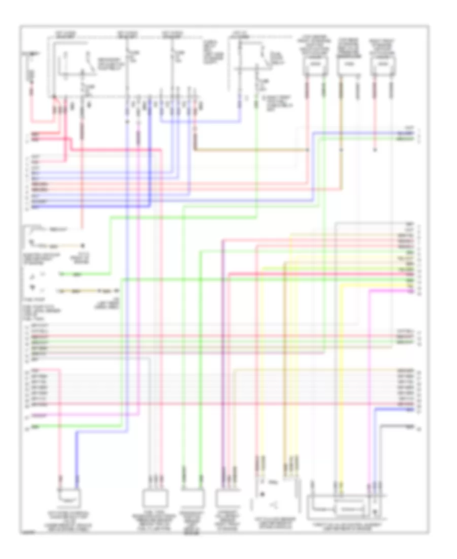
5.0L, Engine Performance Wiring Diagram (1 of 3) for Mercedes-Benz ML500 2005

List of elements for 5.0L, Engine Performance Wiring Diagram (1 of 3) for Mercedes-Benz ML500 2005:
- (behind right kick panel) w29/2
- (left side of engine compt) fuse & relay box
- A11
- B10
- C/b
- C/e
- Check engine indicator
- Computer data lines system
- Cooling fans system
- Data link connector (dtc readout) (below left side of dash)
- Engine control module (me-sfi) (left side of engine compt, in e box)
- Fuse 15a
- Hot at all times
- Instrument cluster
- Kickdown switch (below accelerator pedal)
- Left oxygen sensor 1 (before twc) (in exhaust pipe)
- Left oxygen sensor 2 (after twc) (in exhaust pipe)
- Low engine oil indicator
- Nca
- P/b
- P/d
- Pedal value sensor (left rear corner of engine compt)
- Pnk
- Purge control valve (left rear corner of engine compt)
- Red
- Right front footwell fuse & relay box
- Right oxygen sensor 1 (before twc) (in exhaust pipe)
- Right oxygen sensor 2 (after twc) (in exhaust pipe)
- Starting system
- W16 (left rear corner of eng compt)
5.0L, Engine Performance Wiring Diagram (2 of 3) for Mercedes-Benz ML500 2005
List of elements for 5.0L, Engine Performance Wiring Diagram (2 of 3) for Mercedes-Benz ML500 2005:
- (right front of engine) air pump switchover valve
- (top center front of engine) shifting induction pipe switchover valve
- (top rear of engine) egr valve pressure transducer
- Activated charcoal canister shut-off valve (under rear of vehicle, above spare wheel)
- Battery
- C/d
- Camshaft hall-effect sensor (right front of engine)
- Crankshaft position sensor (left rear of engine)
- Electric air pump (center front of engine)
- Fuel pump
- Fuel pump relay
- Fuel pump with fuel level sensor (top of fuel tank)
- Fuel tank emissions monitoring pressure sensor (behind trim on fuel filler pipe)
- Fuse & relay box (left side of engine compt)
- Fuse 15a
- Fuse 20a
- Fuse 40a
- Hot at all times
- Hot film maf sensor (center rear of intake manifold)
- Hot in run or start
- M/a
- Mr/c
- Mr/d
- Mr/e
- P/d
- P/e
- Pnk
- Red
- Right front footwell fuse & relay box
- Secondary air injection pump relay
- Throttle valve control element (center rear of engine)
- W11/3 (front of engine)
- W6 (left rear cargo area)
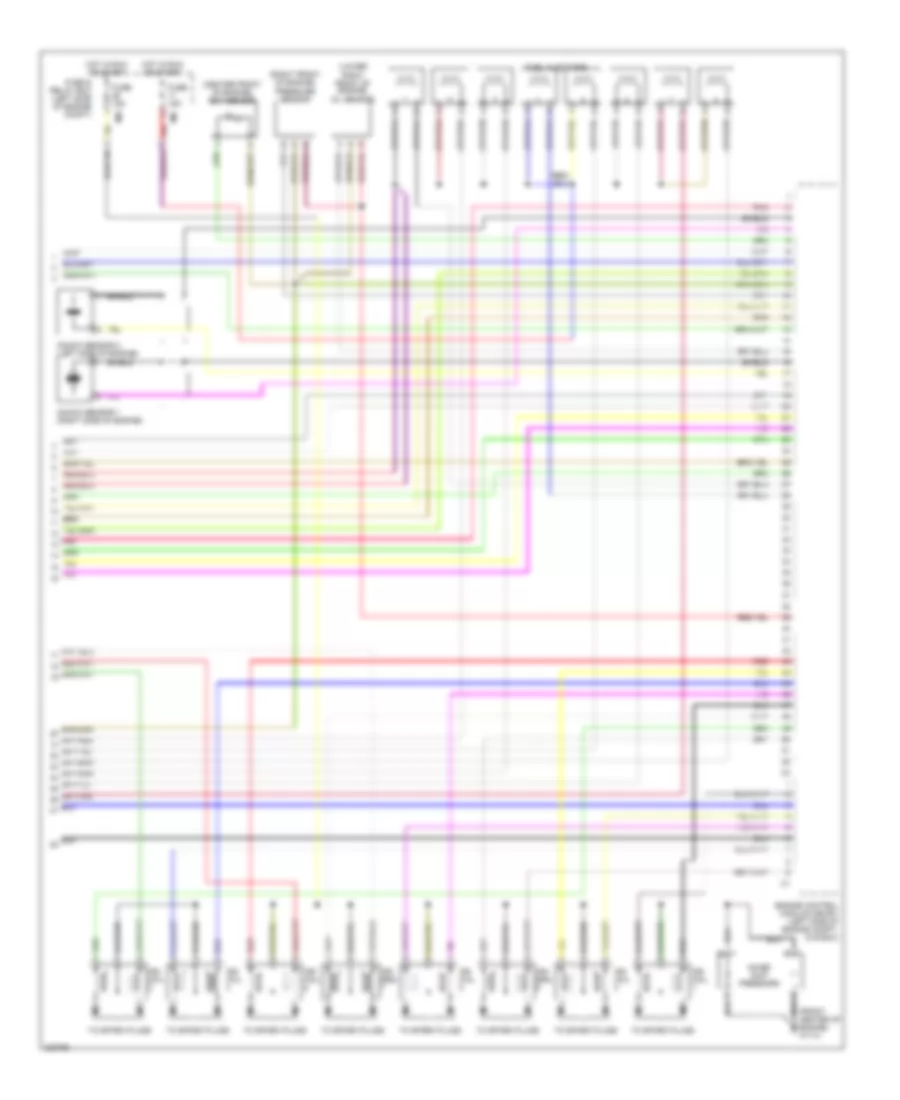
5.0L, Engine Performance Wiring Diagram (3 of 3) for Mercedes-Benz ML500 2005
List of elements for 5.0L, Engine Performance Wiring Diagram (3 of 3) for Mercedes-Benz ML500 2005:
- (center front of engine) ect sensor
- (front center of engine) w11/3
- (lower right front of engine) oil sensor
- (right front of engine) pressure sensor
- Engine control module (me-sfi) (left side of engine compt, in e box)
- Fuel injectors
- Fuse & relay box (left side of engine compt)
- Fuse 15a
- Hot in run or start
- Ign coil
- Ign coil coil
- Knock sensor 1 (right side of engine)
- Knock sensor 2 (left side of engine)
- M/a
- M/c
- Noise sup- pressors
- Pnk
- Red
- Shield
- To spark plugs