ENGINE PERFORMANCE
5.5L
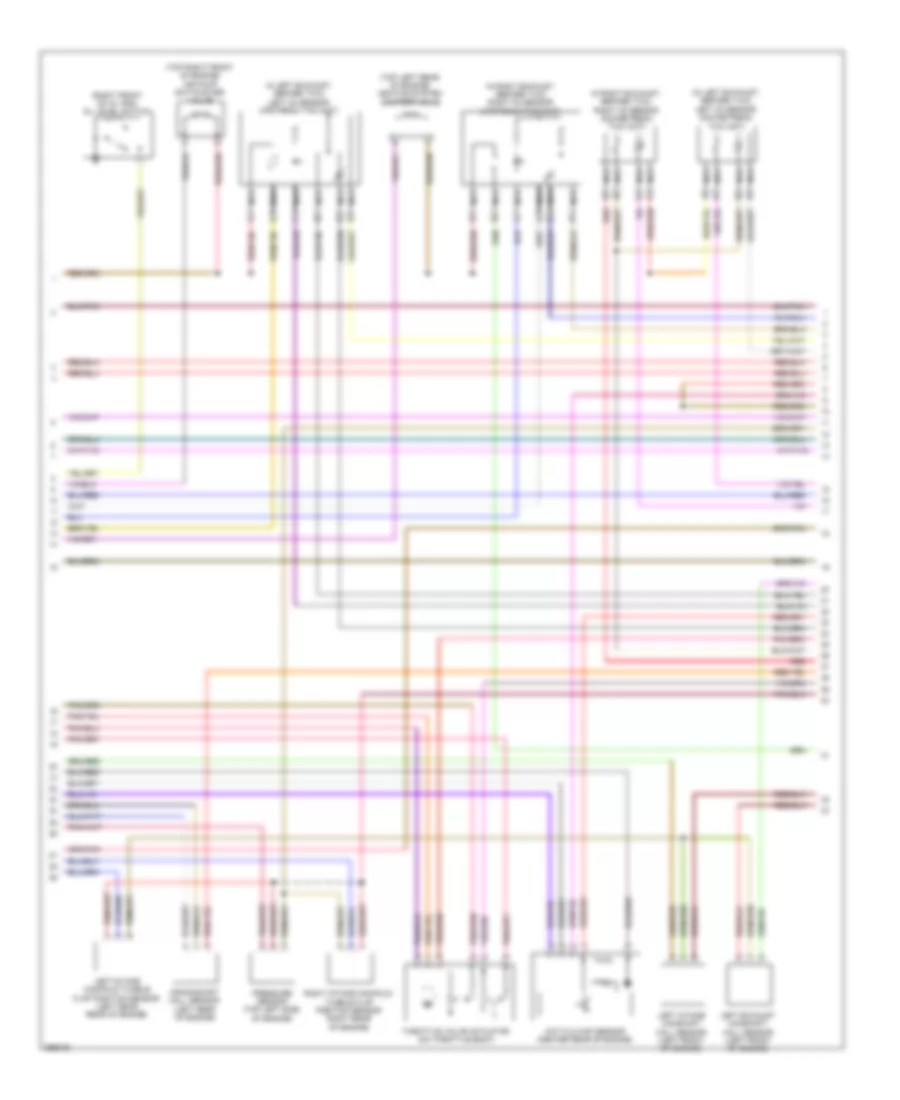
5.5L, Engine Performance Wiring Diagram (1 of 5) for Mercedes-Benz ML550 2008

List of elements for 5.5L, Engine Performance Wiring Diagram (1 of 5) for Mercedes-Benz ML550 2008:
- (in right rear wheelwell)
- Accelerator pedal sensor (top of accelerator pedal assembly)
- Activated charcoal filter shutoff valve
- Air pump relay
- Akf
- Can-c h
- Can-c l
- Computer data lines system
- Electric suction fan engine & a/c w/ integrated control (center front of engine compt)
- Engine circuit 87 relay
- Engine compartment fuse & relay box (right side of engine compt)
- Fuel pump module relay
- Fuel tank pressure sensor (inside fuel tank)
- Fuse 10a
- Fuse 15a
- Fuse 20a
- Fuse 40a
- Fuse 5a
- Hot at all times
- Hot w/ circuit 15 relay energized
- Hot w/ starter relay energized
- Kpr
- Load compartment fuse & relay box (right side of cargo area)
- Lues
- Me-sfi control module (center rear of engine)
- Mr1
- Mr2
- Mr3
- Mr4
- Pnk
- Purge control valve (left side of engine compt)
- Restraints system control module
- Slp
- Sp1m
- Sp1s
- Sp2m
- Sp2s
- Starting/charging system
- Usp1
- W16/3 (left rear of engine compt)
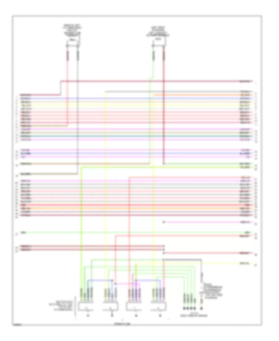
5.5L, Engine Performance Wiring Diagram (2 of 5) for Mercedes-Benz ML550 2008
List of elements for 5.5L, Engine Performance Wiring Diagram (2 of 5) for Mercedes-Benz ML550 2008:
- (+)
- (-)
- (front of engine) (w/ wiring harness wiring harness installed but nonfuntional) three disk thermostat valve
- (front of intake manifold)
- (left rear of engine) w11w2
- (ml-class: under intake manifold) (gl-class: top center of engine)
- (not used)
- (on power steering pump) power steering pump pressure regulator valve
- Air pump (top front of engine)
- Can-d h
- Can-d l
- Computer data lines system
- Ev 7
- Fuel pressure sensor
- Fuel pump control module
- Fuse 20a
- Fuse 5a
- Hot at all times
- Hot w/ circuit 15 relay energized
- Intake manifold tumble flap switchover valve
- Kw out
- Left knock sensor 2
- Load compartment fuse & relay box (right side of cargo area)
- Me-sfi control module (center rear of engine)
- Nca
- Red
- Right fuel pump (in right side of fuel tank)
- Right knock sensor 1
- Variable intake manifold switchover valve
- W17 (under right rear seat)
- W17 (under right seat of 2nd row)
- X26
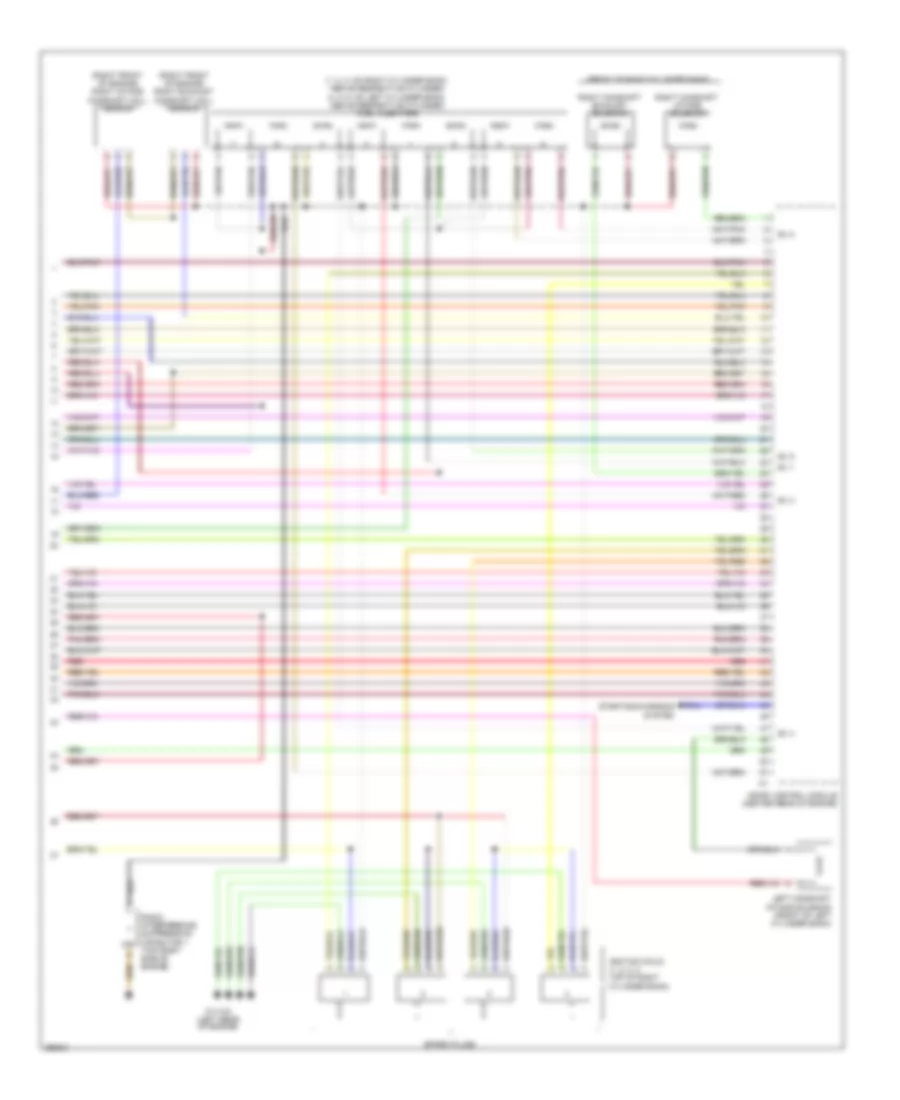
5.5L, Engine Performance Wiring Diagram (3 of 5) for Mercedes-Benz ML550 2008
List of elements for 5.5L, Engine Performance Wiring Diagram (3 of 5) for Mercedes-Benz ML550 2008:
- (in left exhaust, before twc) left o2 sensor downstream twc (kat)
- (right front of oil pan) oil level switch
- (top left rear of engine) heating system shutoff valve
- (top right front of engine) air pump switchover valve
- Crankshaft hall sensor (left rear of engine)
- Hot film maf sensor (center rear of engine)
- In left exhaust, before twc) left o2 sensor upstream twc (kat)
- In right exhaust, before twc) right o2 sensor downstream twc (kat)
- In right exhaust, before twc) right o2 sensor upstream twc (kat)
- Left exhaust camshaft hall sensor (left front of engine)
- Left intake camshaft hall sensor (left front of engine)
- Left intake manifold tumble flap position sensor (left rear rear of engine)
- Nca
- Pressure sensor (top left side of engine)
- Red
- Right intake manifold tumble flap position sensor right rear of engine)
- Throttle valve actuator (on throttle body)
5.5L, Engine Performance Wiring Diagram (4 of 5) for Mercedes-Benz ML550 2008
List of elements for 5.5L, Engine Performance Wiring Diagram (4 of 5) for Mercedes-Benz ML550 2008:
- (left front of engine) left camshaft exhaust solenoid
- (rear of left cylinder bank) coolant temperature sensor
- Ignition coils (gl-class: 5, 6, 7 & 8: top of left cylinder bank)
- Radio interference suppression capacitor 2 (top left side of engine)
- Red
- Spark plugs
- W11w1 (right rear of engine)
5.5L, Engine Performance Wiring Diagram (5 of 5) for Mercedes-Benz ML550 2008
List of elements for 5.5L, Engine Performance Wiring Diagram (5 of 5) for Mercedes-Benz ML550 2008:
- (1, 2, 3: on right cylinder bank, above respective cylinder) (4, 5, 6: on left cylinder bank, above respective cylinder) fuel injectors
- (front of right cylinder bank)
- (right front of engine) right exhaust camshaft hall sensor
- (right front of engine) right intake camshaft hall sensor
- Ev 1
- Ev 3
- Ev 4
- Ev 5
- Ev 8
- Ignition coils (1, 2, 3, 4: top of right cylinder bank)
- Left camshaft intake solenoid (front of left cylinder bank)
- Me-sfi control module (center rear of engine)
- Radio interference suppression capacitor 1 (top right side of engine)
- Red
- Right camshaft exhaust solenoid
- Right camshaft intake solenoid
- Spark plugs
- Starting/charging system
- W11w2 (left rear of engine)