ENGINE PERFORMANCE
4.6L
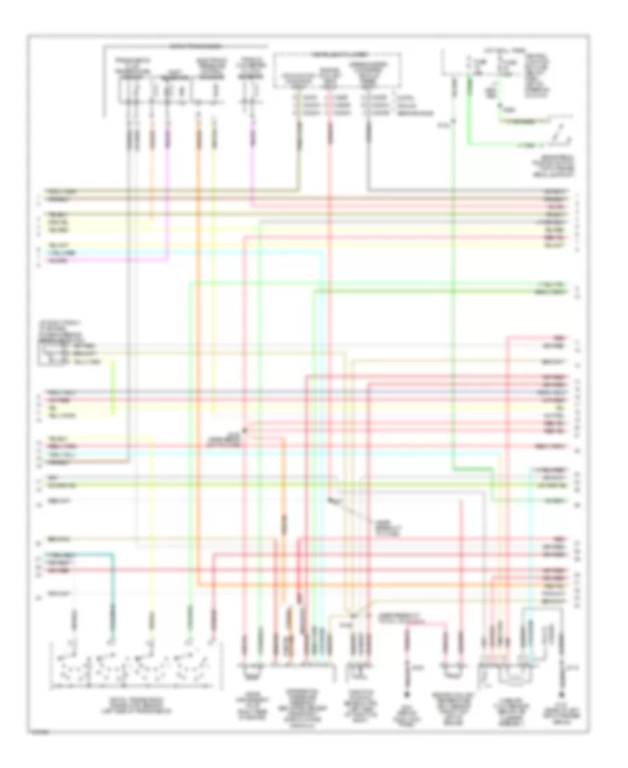
4.6L, Engine Performance Wiring Diagram (1 of 4) for Mercury Grand Marquis GS 2004

List of elements for 4.6L, Engine Performance Wiring Diagram (1 of 4) for Mercury Grand Marquis GS 2004:
- (-)
- (in dash panel to headlamp junc- tion harn, near breakout to c1047)
- (in eng control sensor & fuel charge wiring harn, near breakout at left rear of eng)
- (in eng control sensor & fuel charge wiring harn, near breakout to c1033)
- (left center of eng)
- (marauder)
- (marauder) (others)
- (others)
- (others) (marauder)
- (rear of left front fender apron) g101
- (right front of engine) knock sensor
- (right rear of eng)
- A/c air temp in
- A/c cutout
- A/c evaporator discharge air temperature sensor (right side rear of eng compt)
- A/c system
- Anti-theft system
- Battery junction box (bjb) (right front of engine compt, behind battery)
- Case gnd
- Central junction box (cjb) (below dash, left of steering column)
- Charging system
- Ckp (+)
- Ckp (-)
- Coil 1
- Coil 3
- Coil 4
- Coil 5
- Coil 6
- Cooling fans
- Crankshaft position sensor (lower right front of engine)
- Crankshaft position sensor shield
- Cyl head temp
- Data link (+)
- Data link (-)
- Data link connector (dlc) (behind left side of dash)
- Ect ind
- Egr vac reg
- Eprom
- Fan high rly
- Fan low rly
- Floor shifter
- Fuel door ind
- Fuel flow
- Fuel gauge
- Fuel pump
- Fuse 15a
- Fuse 25a
- Fuse 30a
- G101 (rear of left front fender apron)
- Gen "s" term
- Gnd
- Hot at all times
- Hot in run or start
- Iat sens in
- Ignition coils
- Ignition trans- former capa- citor 1&2 (marauder)
- Ignition transformer capacitor (left front of engine)
- Instrument cluster system
- Knock sens sig
- Led sig gnd
- Maf sig rtn
- Map sens in
- Marauder
- Marauder others
- Mil
- Nca
- Others
- Overdrive cancel switch
- Pcm power diode
- Pcm power relay
- Powertrain control module (pcm) (in engine compt, on left side of firewall)
- Psp sens in
- Pwr gnd
- Rt ho2s 12
- Rx sig
- S101
- S103
- S111
- S115
- S117
- S118
- S134
- S135
- S140
- S151
- S160
- S223
- S276
- Shft sol a
- Shft sol b
- Starting system
- Starting/charging system
- Tach sig
- Tcil
- Tr1
- Tr2
- Tr4
- Trans ctrl sw
- Trans temp
- Transmissions system
- Tx sig
- W/ center console
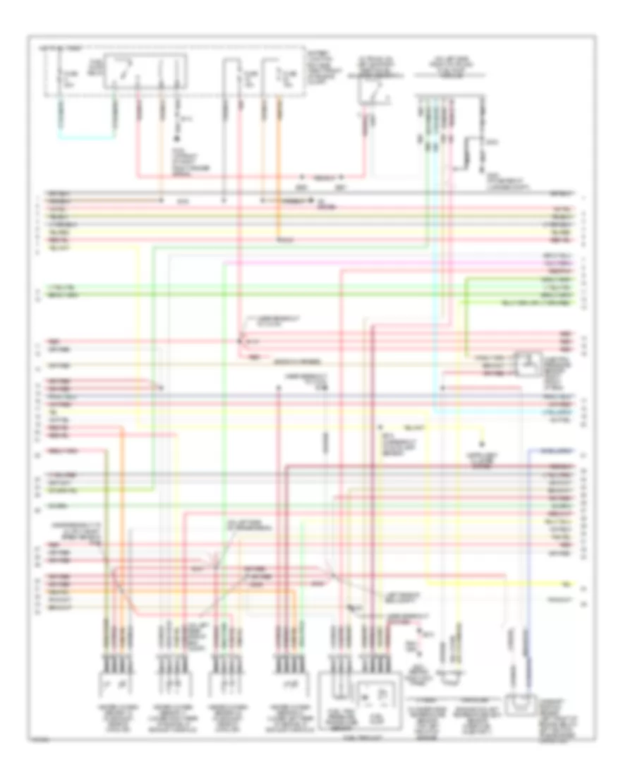
4.6L, Engine Performance Wiring Diagram (2 of 4) for Mercury Grand Marquis GS 2004
List of elements for 4.6L, Engine Performance Wiring Diagram (2 of 4) for Mercury Grand Marquis GS 2004:
- (at right front of engine)
- (near break- out to c1033)
- (near breakout to c1026)
- (near breakout to coil on plug 4)
- (speedometer/ odometer) vehicle speed input
- 4r70w transmission
- Analog
- Brake pedal position switch (top of brake pedal support)
- C220b
- C220c
- C2220a
- C2220b
- Central junction box (cjb) (below dash, left of steering column)
- Differential pressure feedback egr (dpfe) sensor (near right side of intake manifold)
- Digital
- Digital transmission range (dtr) sensor (left side of transmission)
- Electronic pressure control solenoid
- Engine coolant temp input
- Engine coolant temperature (ect) sensor (front top left of engine)
- Fuse 15a
- G101 (rear of left front fender apron)
- G201 (behind right kick panel)
- Hot at all times
- Instrument cluster
- Malfunction indicator input
- Mass air- flow sensor (behind air cleaner assembly)
- Others
- Performance
- Police
- Power steering pressure switch
- R n
- Red
- Red marauder
- S118
- S126
- S128
- S132
- S141
- S150
- S265
- Shift solenoids
- Ssa
- Ssb
- Throttle position sensor (tps) (left side of throttle body)
- Torque converter clutch solenoid
- Transmission fluid temperature sensor
- Vapor management valve (right rear of engine)
4.6L, Engine Performance Wiring Diagram (3 of 4) for Mercury Grand Marquis GS 2004
List of elements for 4.6L, Engine Performance Wiring Diagram (3 of 4) for Mercury Grand Marquis GS 2004:
- (ends in harness)
- (in trunk, on left support) inertia fuel shut-off (ifs) switch
- (left rear of eng compt)
- (near breakout to c1019)
- (near breakout to c1026)
- (near breakout to c1033 s123
- (near breakout to output shaft speed sensor) s146
- (on left side front of trunk) fuel pump module
- (on left side of transmission)
- A/c system
- Battery junction box (bjb) (right front of engine compt)
- Camshaft position sensor (left front of engine, below left ignition transformer capacitor)
- Cylinder-head temperature sensor (top left front of engine)
- Engine coolant temperature (ect) sensor (near fuel injector 1)
- Fuel pump
- Fuel pump relay
- Fuel tank pressure transducer sensor
- Fuel tank unit
- Fuse 15a
- Fuse 20a
- G102 (at front of right front fender apron)
- G201 (behind right kick panel)
- G400 (at center of luggage compt)
- Heated oxygen sensor 11 (lower right rear of engine, in exhaust manifold)
- Heated oxygen sensor 12 (in exhaust, rear of catalyst)
- Heated oxygen sensor 21 (lower left rear of engine, in exhaust manifold)
- Heated oxygen sensor 22 (in exhaust, rear of catalyst)
- Hot at all times
- Injection pressure sensor (right front of eng)
- Instrument cluster system
- Marauder
- Nca
- Others
- Red
- Red/pnk
- S109
- S110
- S113
- S125
- S130
- S143
- S147
- S210
- S210 (in breakout to autolamp sensor)
- S256
- S267
- S286
- S303
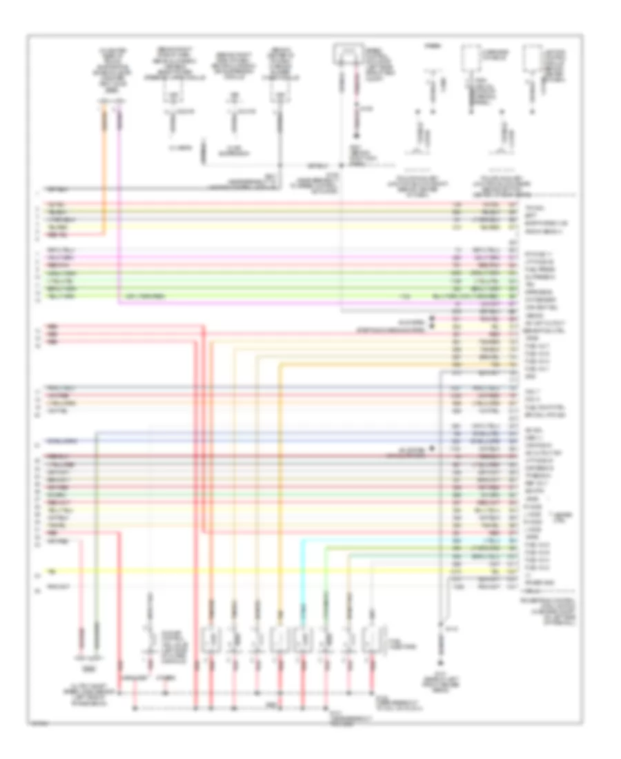
4.6L, Engine Performance Wiring Diagram (4 of 4) for Mercury Grand Marquis GS 2004
List of elements for 4.6L, Engine Performance Wiring Diagram (4 of 4) for Mercury Grand Marquis GS 2004:
- (+)
- (behind center of of dash) warning buzzer/ chime module
- (behind right side of dash, above glove box) air suspension module
- (behind right side of dash, above glove box) variable assist power steering (vaps) module
- (in center rear of trunk) evaporative emission (evap) canister vent valve
- A/c cutout sw
- A/c system
- A/c system (a/c clutch sw)
- A/c wot cutout
- Batt
- C2131b
- C2145b
- C2231b
- C2232b
- C290c
- C4170d
- C9013a (w/ roof opening panel)
- Cam pos in
- Can vent sol
- Cht sensor
- Coil 2
- Coil 7
- Coil 8
- Compt)
- Dpfe sens
- Epc sol rtn sig
- Evap purge vlve
- Fuel inj 1
- Fuel inj 2
- Fuel inj 3
- Fuel inj 4
- Fuel inj 5
- Fuel inj 6
- Fuel inj 7
- Fuel inj 8
- Fuel injectors
- Fuel press
- Fuel pump ctrl
- G101 (rear of left front fender apron)
- G201 (behind right kick panel)
- Gen/bat ind ctrl
- Gnd
- Heater ctrl
- Iac sol
- Idle air control (iac) valve (left side of intake manifold)
- Inj press in
- Knock sens (+)
- L ho2s
- Lft ho2s 21
- Lft ho2s 22
- Lighting control module (behind center of dash)
- Maf sens in
- Marauder
- Oss (+)
- Others
- Output shaft speed (oss) sensor (left side of transmission)
- Overhead console
- Police auxiliary junction block (front) (behind center of dash)
- Police auxiliary junction block (rear) (behind bottom center of rear seats)
- Power gnd
- Powertrain control module (pcm) (in engine compt, on left side of firewall)
- R ho2s
- Radio
- Red
- Red/pnk
- Ref volt
- Rt ho2s 11
- S118
- S128
- S129 (near breakout to speed control actuator)
- S131 (near breakout to c1033)
- S148 (near breakout to coil on plug 4)
- S247 (near breakout to lighting control module)
- Sig rtn
- Speed control actuator (left rear side of eng
- Starting/charging system
- Tan
- Tan/red
- Tcc sol
- Tp sens in
- Tr3
- Vpwr
- Vss (+)
- Vss sig
- W/ air suspension
- W/ varps