ENGINE PERFORMANCE
2.0L
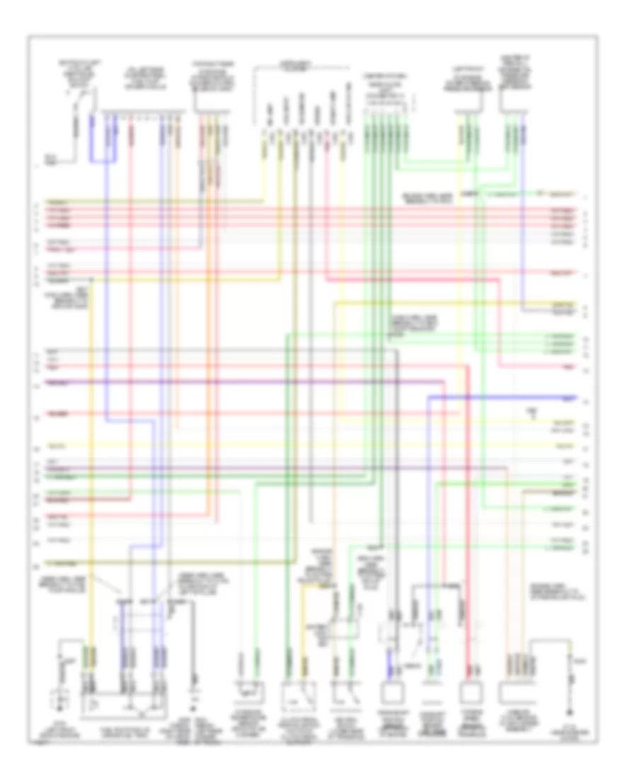
2.0L, Engine Performance Wiring Diagrams (1 of 3) for Mercury Tracer GS 1999

List of elements for 2.0L, Engine Performance Wiring Diagrams (1 of 3) for Mercury Tracer GS 1999:
- (a/t)
- (engine harn, near breakout to constant control relay module)
- (engine harn, near breakout to eng compt fuse box)
- (engine harn, near breakout to pcm)
- (fuel inj harn, near breakout to noise capacitor) s107
- (near starter motor)
- A/c on input
- Air conditioning
- Battery junction box
- Battery junction fuse box
- C110
- C220
- Central junction box
- Coil output
- Constant control relay module
- Cooling fans
- Crank sens (+)
- Crank sens (-)
- Data link connector (under left side of dash)
- Dlc 2 bus (+)
- Dlc 2 bus (-)
- Ect sens in
- Egr vac reg
- Egr vacuum regulator (center of firewall)
- Engine coolant temperature sensor (left rear of engine)
- Engine fuse 15a
- Epc
- Eprom pwr
- Exterior lights
- Fuel gauge
- Fuel inj fuse 10a
- Fuel injector fuse 30a
- Fuel pump fuse 30a
- Fuel pump mon
- Fuel pump relay
- G112
- Ground
- Hi fan ctrl
- Ho2s-12
- Hot at all times
- Hot in run or start
- Iat sens in
- Ignition coil (left side of engine)
- Irm solenoid
- Lo fan ctrl
- Maf return
- Mil ind ctrl
- Nca
- Pcm power relay
- Powertrain control module (below center of dash)
- Psp sensor
- Radio noise capacitor (top left of engine)
- Red
- S101
- S102
- S106
- S110 (engine harn, near breakout to eng compt fuse box)
- S112
- S113
- S204
- S205
- S231
- Shield ground
- Shift sol 1
- Shift sol 2
- Shift sol 3
- Spark plugs
- Tach output
- Tcc
- Tcc sol
- Tft
- Trans - drive
- Trans - low
- Trans - od
- Trans - rev
- Trans temp
- Transaxle
- Transmission range sensor (top of transaxle)
- Turbine sens (-)
- Vss (-)
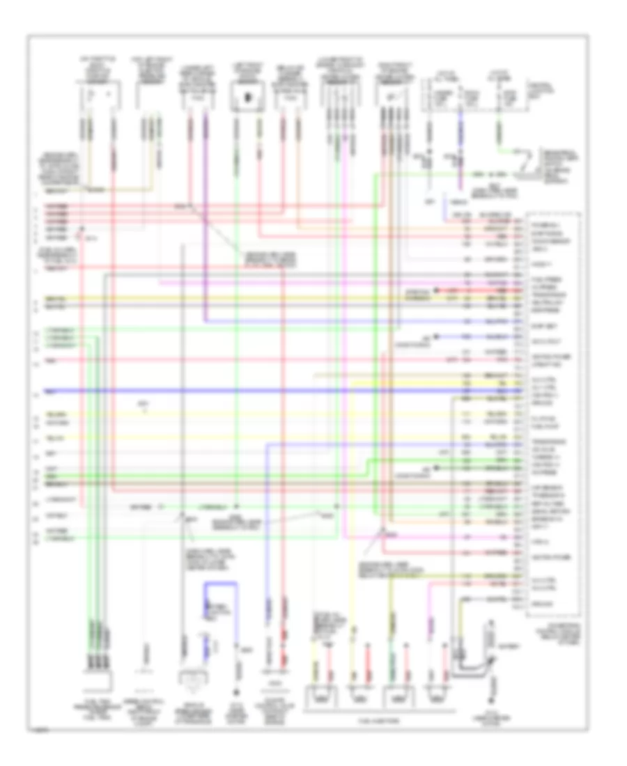
2.0L, Engine Performance Wiring Diagrams (2 of 3) for Mercury Tracer GS 1999
List of elements for 2.0L, Engine Performance Wiring Diagrams (2 of 3) for Mercury Tracer GS 1999:
- (bottom of left "a" pillar) inertia fuel shutoff switch
- (center of dash,
- (center of firewall) differential pressure feedback egr sensor
- (dash harn, near breakout to eng compt grommet) s128
- (eng harn, near breakout to octane adjust plug)
- (engine harn, near breakout to octane adjust plug)
- (engine harn, near breakout to octane adjust plug) s264
- (engine harn, near breakout to pcm)
- (left front
- (on left rear quarter panel) fuel pump driver module
- (rear harn, near breakout to 10-pin inline conn at left "b" pillar)
- (rear harn, near breakout to fuel pump module)
- (sedan) (left rear corner
- (top right rear
- 1999-00
- Battery junc- tion box
- C110
- C252
- C253
- C254
- Camshaft position sensor (left rear of engine)
- Clutch pedal position switch (on top of clutch pedal support)
- Crankshaft
- Fuel cap off ind
- Fuel input
- Fuel pump module (inside fuel tank)
- G100 (left front side of engine)
- G112 (near starter motor)
- G404 g405 (wagon) (right rear of cargo area) of trunk)
- Instrument cluster
- Intake air temperature sensor (front of air cleaner)
- Mass air- flow sensor (in air cleaner assembly)
- Mil lamp
- Nca
- Near floor) joint connector 10
- Neutral switch (lower rear of transaxle)
- Of engine) intake manifold runner control solenoid (imrc)
- Of engine) power steering pressure sensor
- Pnk
- Position sensor (left front of engine)
- Red
- S207
- S207 (main harn, near breakout to ground g206)
- S226
- S228
- S230
- S301
- S315
- S423
- Sensor (on top of transaxle)
- Speedo
- Tachometer
- Turbine speed
- Upshift lamp
2.0L, Engine Performance Wiring Diagrams (3 of 3) for Mercury Tracer GS 1999
List of elements for 2.0L, Engine Performance Wiring Diagrams (3 of 3) for Mercury Tracer GS 1999:
- (360 or)
- (a/t)
- (below air cleaner assembly) evap canister purge valve
- (dash harn, near breakout to 16-pin conn at lower center of dash)
- (engine harn, near breakout to 16-pin conn below center of dash)
- (engine harn, near breakout to 16-pin inline conn at right rear of engine compartment)
- (engine harn, near breakout to brake fluid level switch)
- (engine harn, near breakout to pcm)
- (fuel inj harn, near breakout to fuel inj 3)
- (left front of engine) knock sensor
- (lower front of engine, in exhaust manifold) heated oxygen sensor 12
- (m/t)
- (on throttle body) throttle position sensor
- (right front of engine) heated oxygen sensor 11
- (top left front of engine) injection pressure sensor
- (under left rear corner of vehicle) evap canister vent solenoid
- 1999-00
- A/c cutout
- A/c press
- Air conditioning
- Battery
- Brake pedal postion (bpp) switch (on brake pedal support)
- Brake sw in
- C111
- Cam pos (+)
- Cam pos (-)
- Central junction box
- Egr press
- Evap purge
- Evap vent
- Fu cp ind
- Fuel injectors
- Fuel press
- Fuel pump
- Fuel tank pressure sensor (inside fuel tank)
- G112 (near starter motor)
- Ground
- Hazard fuse 15a
- Ho2s-11
- Hot at all times
- Hrt-11
- Htr-12
- Iac valve
- Idle air control valve (top right rear of engine)
- Ignition power
- Inj 1 ctrl
- Inj 2 ctrl
- Inj 3 ctrl
- Inj 4 ctrl
- Inj press
- Knock sensor
- Maf sensor
- Nca
- Neutral sw
- Pnk
- Power b(+)
- Powertrain control module (below center of dash)
- Red
- Ref voltage
- Room fuse 15a
- S111
- S114
- S124
- S129
- S206
- S218
- S224
- S225
- S242
- S247 (dash harn, near breakout to pcm)
- S266
- S272
- Signal return
- Speed control servo (right front of engine compt)
- Starting/ charging
- Stop fuse 15a
- Tan
- Tp sensor in
- Trans range
- Turbine (+)
- Upshift ind
- Vehicle speed sensor (lower rear of transaxle)
- Vss (+)