ENGINE PERFORMANCE
1.6L
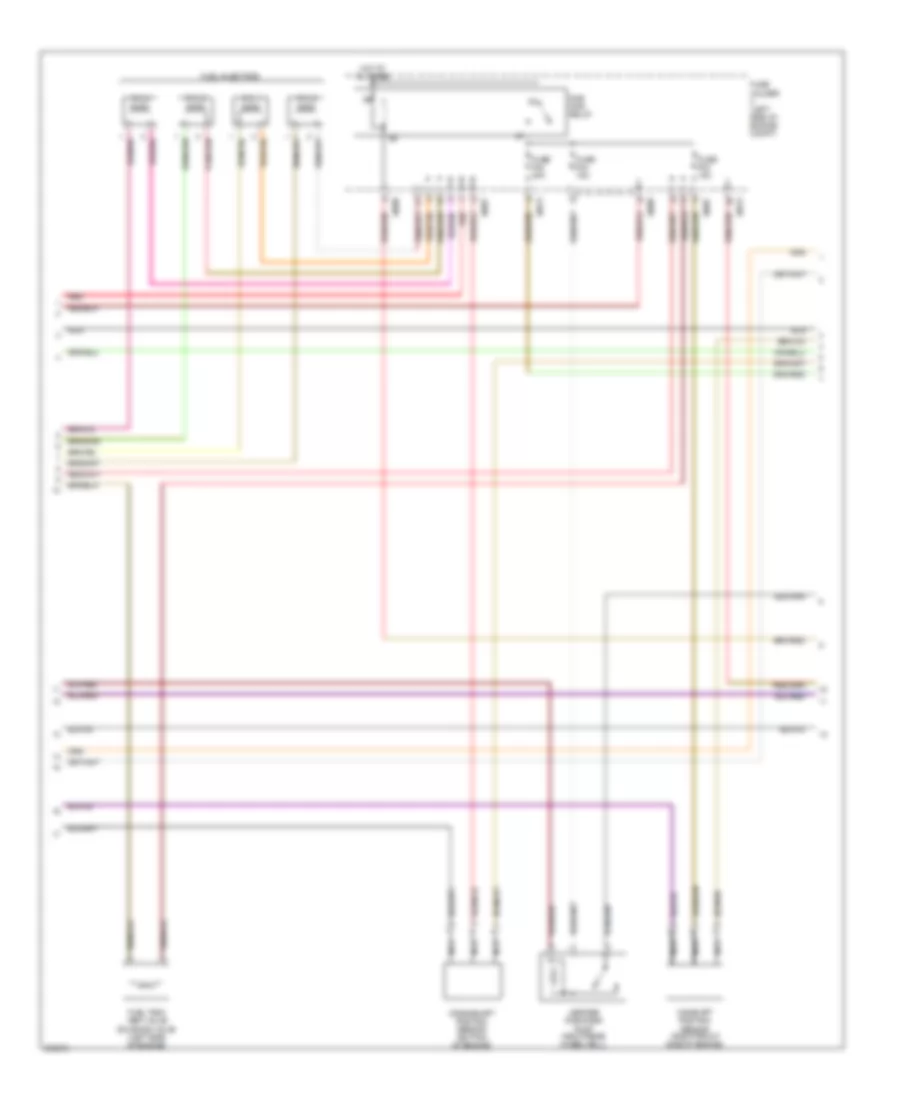
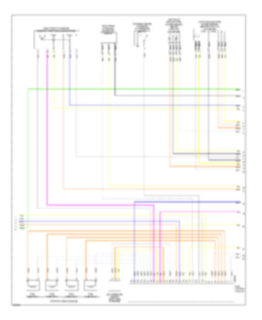
1.6L, Engine Performance Wiring Diagram (1 of 3) for MINI Cooper 2007

List of elements for 1.6L, Engine Performance Wiring Diagram (1 of 3) for MINI Cooper 2007:
- (left side of engine) knock sensor
- (rear of engine) coolant temperature sensor
- (top rear of engine) ignition coil
- Charging system
- Cooper s
- Cruise system
- Digital motor electronics control unit (left side of engine compt)
- Electric fuel pump
- Electronic throttle control housing
- Except cooper s
- Fuel pump relay
- Fuse f34 10a
- Fuse f37 20a
- Fuse holder 2 (behind left footwell trim)
- Hot at all times
- Hot in on or start
- Intake air pressure sensor (before supercharger)
- Intake air temperature sensor (left side of engine)
- Intake vacuum sensor (front of engine compt)
- Nca
- Precatalyst oxygen sensor (front exhaust pipe)
- Red
- Transmission system
- X10204
- X490 (below right rear seat)
- X6000
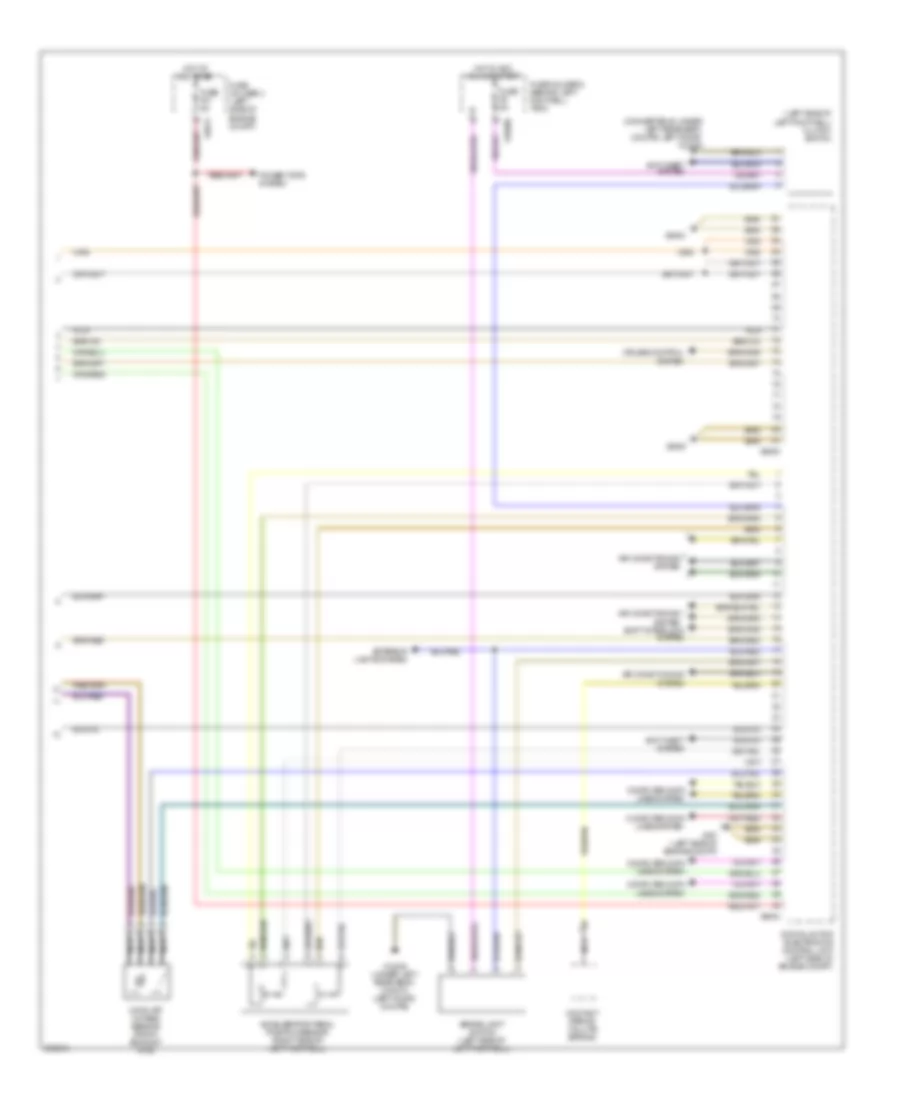
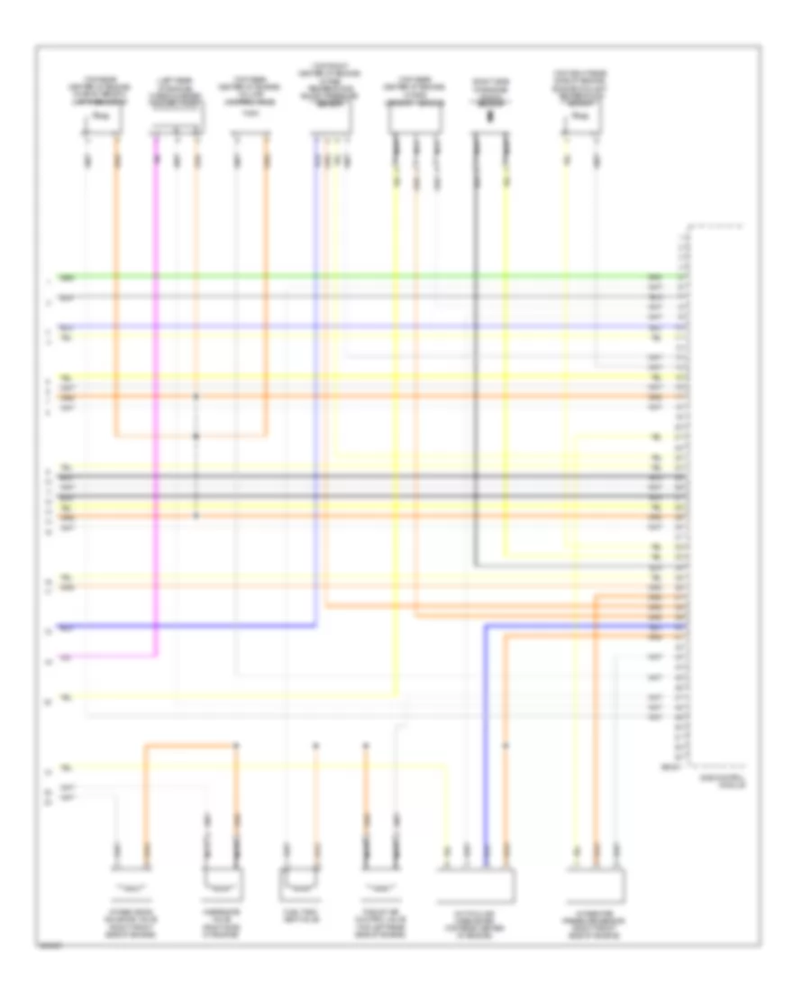
1.6L, Engine Performance Wiring Diagram (2 of 3) for MINI Cooper 2007
List of elements for 1.6L, Engine Performance Wiring Diagram (2 of 3) for MINI Cooper 2007:
- Camshaft position sensor (right front side of engine)
- Crankshaft position sensor (bottom of engine)
- Cyl 1
- Cyl 2
- Cyl 3
- Cyl 4
- Dme main relay
- Fuel injectors
- Fuel tank vent valve solenoid valve (left side of engine)
- Fuse f02 20a
- Fuse f03 15a
- Fuse f04 15a
- Fuse holder (left side of engine compt)
- Hot at all times
- Leakage diagnosis pump (right rear wheelwell)
- Nca
- Red
- X4009
- X4013
- X8687
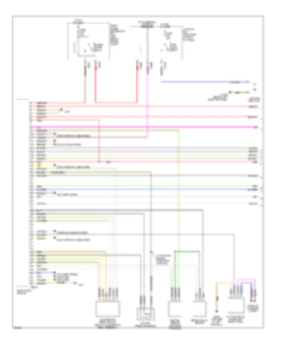
1.6L, Engine Performance Wiring Diagram (3 of 3) for MINI Cooper 2007
List of elements for 1.6L, Engine Performance Wiring Diagram (3 of 3) for MINI Cooper 2007:
- (convertible: under left rear seat) (coupe: left door) x13230
- (left side of left footwell) clutch switch
- Accelerator pedal position sensor (right side of left footwell)
- Air conditioning system
- Anti-theft system
- Brake light switch (left side of left footwell)
- Catalyst oxygen sensor (front exhaust pipe)
- Computer data lines system
- Contact spring (volute spring)
- Cruise control system
- Digital motor electronics control unit (left side of engine compt)
- Exterior lights system
- Fuse f01 5a
- Fuse f6 5a
- Fuse holder 2 (behind left footwell trim)
- Fuse holder 3 (left side of engine compt)
- Hot at all times
- Hot in acc, run or start
- Nca
- Power tops system
- Shift interlock system
- X10200
- X13230 (under left rear seat) (convt) (left door) (coupe)
- X167 (left side of engine compt)
- X4013
- X6000
- X6004
- X6454
1.6L TURBO
1.6L Turbo, Engine Performance Wiring Diagram (1 of 4) for MINI Cooper 2007
List of elements for 1.6L Turbo, Engine Performance Wiring Diagram (1 of 4) for MINI Cooper 2007:
- Accelerator pedal module (part of acceleration pedal assembly)
- Anti-theft system
- Brake vacuum sensor
- Clutch module (under left side of dash)
- Computer data lines system
- Coolant pressure sensor
- Cooling fans system
- Dme control module
- Electric fuel pump
- Front power distribution box (left side of engine compt)
- Fuel pump relay
- Fuse f010 15a
- Fuse f43 20a
- Hot at all times
- Hot w/ terminal 30g relay energized
- Junction box (right side of right footwell)
- Neutral sensor (left rear of engine)
- Power saving relay
- Red
- Starting/ charging system
- Starting/charging system
- W/ automatic engine start-stop function
- X11002
- X11008
- X11010
- X13795 (behind left rear trim panel)
- X167
- X2042 (left side of left footwell)
- X4010
- X4014
- X60004
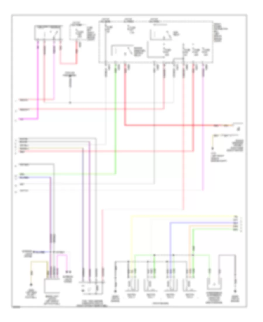
1.6L Turbo, Engine Performance Wiring Diagram (2 of 4) for MINI Cooper 2007
List of elements for 1.6L Turbo, Engine Performance Wiring Diagram (2 of 4) for MINI Cooper 2007:
- (left front side of engine compt)
- (top of engine)
- Brake light switch (left side of left footwell)
- Cooling fans system
- Dme relay
- Engine breather heater 1 (right rear side of engine)
- Engine breather heating relay
- Exterior lights system
- Front power distribution box (left side of engine compt)
- Fuel injectors relay
- Fuel tank leakage diagnostic module (front of right rear wheel)
- Fuse box (right rear of engine compt)
- Fuse f01 5a
- Fuse f02 25a
- Fuse f03 20a
- Fuse f04 20a
- Fuse f05 5a
- Fuse f07 7.5a
- Fuse f68 40a
- Hot at all times
- Ignition coil 1
- Ignition coil 2
- Ignition coil 3
- Ignition coil 4
- Interference suppression capacitor (top right side of engine)
- Red
- X175
- X2042 (left side of left footwell)
- X4009
- X4010
- X4013
- X6401
- X64561 (top of engine)
1.6L Turbo, Engine Performance Wiring Diagram (3 of 4) for MINI Cooper 2007
List of elements for 1.6L Turbo, Engine Performance Wiring Diagram (3 of 4) for MINI Cooper 2007:
- (bottom of exhaust pipe) oxygen sensor (behind catalytic converter)
- (right front of engine) electric throttle valve actuator
- (right rear of engine) crankshaft sensor
- (top of exhaust pipe) oxygen sensor (before catalytic converter)
- (top rear center of engine) oil pressure switch
- (top right side of engine)
- Dme control module
- Fuel injection 1
- Fuel injection 2
- Fuel injection 3
- Fuel injection 4
- Nca
- Rail pressure sensor (right side of engine)
- X60232
1.6L Turbo, Engine Performance Wiring Diagram (4 of 4) for MINI Cooper 2007
List of elements for 1.6L Turbo, Engine Performance Wiring Diagram (4 of 4) for MINI Cooper 2007:
- (left rear of engine) turbocharger coolant pump
- (right side of engine) knock sensor
- (top front center of engine) intake temperature boost pressure sensor
- (top rear center of engine)
- (top rear center of engine) characteristic map thermostat
- (top rear center of engine) volume control valve
- (top right rear side of engine) engine coolant temperature sensor
- Dme control module
- Fuel tank vent valve
- Hot-film air mass meter (top rear center of engine)
- Intake camshaft sensor
- Intake pipe pressure sensor (right front side of engine)
- Intake vanos solenoid valve (right front side of engine)
- Nca
- Thrust air control valve (top left rear side of engine)
- Wastegate valve (right side of engine)
- X60231