ENGINE PERFORMANCE
1.5L TURBO
1.5L Turbo, Engine Performance Wiring Diagram (1 of 4) for MINI Cooper S 2014

List of elements for 1.5L Turbo, Engine Performance Wiring Diagram (1 of 4) for MINI Cooper S 2014:
- (right rear of engine) valvetronic actuator motor
- 3b 15 sply
- 3b sig clutch
- 4b act rly
- 8b bus sig
- Accelerator pedal module (part of acceleration pedal assembly)
- Body domain controller
- Brake light switch (left side of left footwell)
- Brk lt sw sig
- Bus sig flexray
- Clutch module (m/t) (under left side of dash)
- Clutch sig
- Computer data lines system
- Cooling fans system
- Cut-out relay
- Digital motor electronics control unit (left side of engine compt)
- Dme main relay
- Electric fan
- Electrical exhaust flap
- Engine strt sig
- Flap activation term 15 wake up sig
- Flexray
- Flexray bus sig
- Fuel inj sply
- Fuel pmp ctrl
- Fuse 10a
- Fuse 15a
- Fuse 20a
- Fuse 40a
- Gnd
- Hall sens gnd
- Hall sens sig
- Hall sens sply
- Hot at all times
- Ign sply
- Ignition & fuel injection relay
- Leak detection sig
- Lin bus sig
- Motor position sensor
- Mtr activation
- Natural vacuum leak detection
- Pnk
- Pressure switch
- Pt-can bus sig
- Red
- Rly activation
- Sens gnd
- Sens sig
- Sens sply
- Spd sig
- Term
- Term 15
- Term 15 sply
- Term 30b sply
- Valvetronic relay
- Vlv sply
- Z10 1b
- Z10 3b
- Z10 7b
- Z10 8b
- Z6000 1b
1.5L Turbo, Engine Performance Wiring Diagram (2 of 4) for MINI Cooper S 2014
List of elements for 1.5L Turbo, Engine Performance Wiring Diagram (2 of 4) for MINI Cooper S 2014:
- (2.0l turbo) coolant pump changeover valve
- (2.0l turbo) knock sensor 2
- (right side of engine) knock sensor
- Activation
- Characteristic map thermostat (top rear center of engine)
- Coolant pmp
- Coolant pmp gnd
- Cooling fans system
- Crank sens gnd
- Crank sens sig
- Crank sens sply
- Digital motor electronics control unit (left side of engine compt)
- Elec thr act
- Elec thr act gnd
- Elec thr act sig
- Elec thr act sply
- Front power distribution box (left side of engine compt)
- Fuse 5a
- Gear gnd
- Gear sens sig
- Hot at all times
- Hot w/ terminal 15n relay energized
- Hot w/ terminal 30b relay 1 energized
- Knock sens sig
- Lin bus sig
- Map thrmostat
- Oil lvl sens sig
- Oil lvl sens sply
- Oil press ctrl
- Oil press sig
- Oil pressure control valve
- Press sens sig
- Press sens sply
- Radiator outlet
- Sens gnd
- Sply fuel tank
- Starting/ charging system
- Tank vent valve (top left of engine)
- Temp sens sig
- Thr sens gnd
- Vlv activation
- Vlv sply
- Zero gear sensor (top of transmission)
1.5L Turbo, Engine Performance Wiring Diagram (3 of 4) for MINI Cooper S 2014
List of elements for 1.5L Turbo, Engine Performance Wiring Diagram (3 of 4) for MINI Cooper S 2014:
- (top of engine)
- (top of engine) (2.0l turbo) ignition coil cylinder 4
- (top right side of engine) (2.0l turbo) fuel injector cylinder 4
- (top right side of engine) fuel injector cylinder 1
- (top right side of engine) fuel injector cylinder 2
- (top right side of engine) fuel injector cylinder 3
- Crankshaft sensor (right rear of engine)
- Digital motor electronics control unit (left side of engine compt)
- Electric throttle actuator (right front of engine)
- Engine coolant temperature sensor (top right rear side of engine)
- Engine oil pressure sensor (left side of engine)
- Front power distribution box (left side of engine compt)
- Fuel inj 1 activation
- Fuel inj 2 activation
- Fuel inj 3 activation
- Fuel inj 4 activation
- Fuel inj cyl 1
- Fuel inj cyl 2
- Fuel inj cyl 3
- Fuel inj cyl 4
- Fuse 20a
- Hot w/ terminal 30b relay 1 energized
- Ign coil 1 activation
- Ign coil 1 sply
- Ign coil 2 activation
- Ign coil 2 sply
- Ign coil 3 activation
- Ign coil 3 sply
- Ign coil 4 activation
- Ign coil 4 sply
- Ignition coil cylinder 1
- Ignition coil cylinder 2
- Ignition coil cylinder 3
- Intake air temperature pressure sensor (front center of engine compt)
- Intake manifold pressure sensor (right front side of engine)
- Nca
- Oil level sensor
- Radiator outlet temperature sensor
- Spark plug
- Z19 1b
1.5L Turbo, Engine Performance Wiring Diagram (4 of 4) for MINI Cooper S 2014
List of elements for 1.5L Turbo, Engine Performance Wiring Diagram (4 of 4) for MINI Cooper S 2014:
- (right front side of engine) intake vanos solenoid actuator
- (right side of engine) rail pressure sensor
- (top of exhaust pipe) oxygen sensor before catalytic converter
- Camshaft sens gnd
- Camshaft sens sig
- Camshaft sens sply
- Catalytic conv gnd
- Catalytic conv sig
- Catalytic conv sply
- Computer data lines system
- Crash safety module
- Digital motor electronics control unit (left side of engine compt)
- Electric fuel pump (top of fuel tank)
- Electrical wastegate valve (right side of engine)
- Engine ventilation heating (front of right side of engine)
- Exhaust camshaft sensor
- Exhaust vanos solenoid actuator
- Fuel pump control module
- Heating activation
- Heating sply
- Hot film air mass meter (top rear center of engine)
- Intake camshaft sensor (top rear center of engine)
- Meter sig
- Meter sply
- N02 sens sply
- Nca
- Oxygen sens sig
- Oxygen sens sply
- Oxygen sensor after catalytic converter
- Press sens
- Press sens sply
- Quantity control valve (rear of engine)
- Rotor position sensor
- Sens gnd
- Sens sig
- Vanos solenoid sig
- Vanos solenoid sply
- Venturi nozzle pressure sensor
- Vlv activation
- Vlv gnd
- Vlv sply
- Wastegate sig
- Z10 7b
1.6L
1.6L, Engine Performance Wiring Diagram, Clubman (1 of 4) for MINI Cooper S 2014
List of elements for 1.6L, Engine Performance Wiring Diagram, Clubman (1 of 4) for MINI Cooper S 2014:
- (top of fuel tank) electric fuel pump
- Acc gnd
- Acc pedl sens
- Acc sply
- Accelerator pedal module (part of acceleration pedal assembly)
- Act eng rly
- Act fan rly
- Act fuel pump
- Act rly
- Anti- theft system
- Anti-theft system
- Brake lt sw
- Brake vacuum sensor (left rear of engine compt)
- Brk lt sw sig
- Brk snsr
- Bsd sig
- Clutch module (m/t) (under left side of dash)
- Clutch sw
- Computer data lines system
- Cooling fans system
- Dme control unit (left side of engine compt)
- Dme rly
- Electronics junction box
- Front power distribution box (left side of engine compt)
- Fuel pump relay
- Fuse f010 15a
- Fuse f46 20a
- Gnd
- Gnd acc
- Gnd neutral
- Gnd refr
- Hot at all times
- Hot w/ terminal 30g relay energized
- Junction box (right kick panel)
- Neutral sens
- Neutral sensor
- Pa bus sig
- Pt-can hi
- Pt-can lo
- Red
- Refr pr sens
- Refrigerant pressure sensor (rear of engine compt)
- Sig
- Sply sens
- Start rly
- Start/stop function
- Starting/charging system
- Td sig
- Term 15
- Term 15 sply
- Term 30
- Term 87
- Terminal 15 relief relay
- Valvetronic
- W/ automatic engine
- W/o automatic engine
- Wake-up sig
- X11002
- X11008
- X11010
- X13795 (behind left rear trim panel)
- X151 (under front passenger's seat)
- X2042 (left side of left footwell)
- X4010
- X4014
- X60004
1.6L, Engine Performance Wiring Diagram, Clubman (2 of 4) for MINI Cooper S 2014
List of elements for 1.6L, Engine Performance Wiring Diagram, Clubman (2 of 4) for MINI Cooper S 2014:
- (left rear of engine compt) valvetronic relay
- (top left side of engine)
- Brake light switch (left side of left footwell)
- Cooling fans system
- Crankcase ventilation heating relay
- Dme relay
- Engine breather heater 1 (right rear side of engine)
- Exterior lights system
- Front power distribution box (left side of engine compt)
- Fuel tank leakage diagnostic module (front of right rear wheel)
- Fuse box (right rear of engine compt)
- Fuse f01 7.5a
- Fuse f02 25a
- Fuse f03 20a
- Fuse f04 20a
- Fuse f05 7.5a
- Fuse f07 7.5a
- Fuse f67 150a
- Fuse f68 40a
- Hot at all times
- Ignition coil 1
- Ignition coil 2
- Ignition coil 3
- Ignition coil 4
- Interference suppression capacitor (top right side of engine)
- Red
- X13020
- X175 (left front side of engine compt)
- X2042 (left side of left footwell)
- X4009
- X4010
- X4013
- X5353
- X6401
- X64561 (center of top left side of engine)
- X65399
1.6L, Engine Performance Wiring Diagram, Clubman (3 of 4) for MINI Cooper S 2014
List of elements for 1.6L, Engine Performance Wiring Diagram, Clubman (3 of 4) for MINI Cooper S 2014:
- (bottom of exhaust pipe) oxygen sensor (behind catalytic converter)
- (right front of engine) electric throttle valve actuator
- (right rear of engine) crankshaft sensor
- (top of exhaust pipe) oxygen sensor (before catalytic converter)
- (top right rear side of engine) engine coolant temperature sensor
- Act oil pr ctrl
- Act sol vlve exh
- Act sol vlve int
- Crankshaft sens
- Dme control unit (left side of engine compt)
- Eccentric shaft sensor (top right rear side of engine)
- Elct vlve actutor
- Gnd elct sens
- Gnd int sens
- Hot-film air mas
- Int sply sens
- Intake camshaft sensor (top right rear side of engine)
- Nca
- Shft sens
- Sig exh sens
- Sig ful inj
- Sig ig coil
- Sig int sens
- X60212
1.6L, Engine Performance Wiring Diagram, Clubman (4 of 4) for MINI Cooper S 2014
List of elements for 1.6L, Engine Performance Wiring Diagram, Clubman (4 of 4) for MINI Cooper S 2014:
- (front center of engine) friction wheel drive
- (left side of engine) engine oil pressure sensor
- (right rear of engine) valvetronic servo motor
- (right side of engine) knock sensor
- (top right rear side of engine)
- (top right side of engine)
- Act oxygen sens
- Act sens heater
- Characteristic map thermostat (right rear side of engine)
- Crnkshaft sens
- Dme control unit (left side of engine compt)
- Elct actuator
- Eng oil pr sens
- Eng temp sens
- Eng temp sig
- Exh sens
- Exhaust camshaft sensor
- Exhaust vanos solenoid valve (top right front side of engine)
- Fuel injection 1
- Fuel injection 2
- Fuel injection 3
- Fuel injection 4
- Fuel tank vent valve (top left of engine)
- Fuel vet valve
- Fuil inj
- Hot-film air mas
- Hot-film air mass meter (top rear center of engine)
- Int temp sens
- Intake temperature differential pressure sensor (right rear side of engine)
- Intake vanos solenoid valve (right front side of engine)
- Knock sens
- Map thermostat
- Nca
- Oil pressure regulating valve (front right side of engine)
- Oxygen sens
- Oxygen sens sig
- Pr sens
- Sig vlve
- Sply
- Term 15
- Term 87
- Valve servo
- Wheel drive
- X60211
1.6L, Engine Performance Wiring Diagram, Convertible (1 of 4) for MINI Cooper S 2014
List of elements for 1.6L, Engine Performance Wiring Diagram, Convertible (1 of 4) for MINI Cooper S 2014:
- (top of fuel tank) electric fuel pump
- Acc gnd
- Acc pedl sens
- Acc sply
- Accelerator pedal module (part of acceleration pedal assembly)
- Act eng rly
- Act fan rly
- Act fuel pump
- Act rly
- Anti- theft system
- Anti-theft system
- Brake lt sw
- Brake vacuum sensor (left rear of engine compt)
- Brk lt sw sig
- Brk snsr
- Bsd sig
- Clutch module (m/t) (under left side of dash)
- Clutch sw
- Computer data lines system
- Cooling fans system
- Dme control unit (left side of engine compt)
- Dme rly
- Electronics junction box
- Front power distribution box (left side of engine compt)
- Fuel pump relay
- Fuse f010 15a
- Fuse f46 20a
- Gnd
- Gnd acc
- Gnd neutral
- Gnd refr
- Hot at all times
- Hot w/ terminal 30g relay energized
- Junction box (right kick panel)
- Neutral sens
- Neutral sensor
- Pa bus sig
- Pt-can hi
- Pt-can lo
- Red
- Refr pr sens
- Refrigerant pressure sensor (rear of engine compt)
- Sig
- Sply sens
- Start rly
- Start/stop function
- Starting/charging system
- Td sig
- Term 15
- Term 15 sply
- Term 30
- Term 87
- Terminal 15 relief relay
- Valvetronic
- W/ automatic engine
- W/o automatic engine
- Wake-up sig
- X11002
- X11008
- X11010
- X13795 (behind left rear trim panel)
- X151 (under front passenger's seat)
- X2042 (left side of left footwell)
- X4010
- X4014
- X60004
1.6L, Engine Performance Wiring Diagram, Convertible (2 of 4) for MINI Cooper S 2014
List of elements for 1.6L, Engine Performance Wiring Diagram, Convertible (2 of 4) for MINI Cooper S 2014:
- (left rear of engine compt) valvetronic relay
- (top left side of engine)
- Brake light switch (left side of left footwell)
- Cooling fans system
- Crankcase ventilation heating relay
- Dme relay
- Engine breather heater 1 (right rear side of engine)
- Exterior lights system
- Front power distribution box (left side of engine compt)
- Fuel tank leakage diagnostic module (front of right rear wheel)
- Fuse box (right rear of engine compt)
- Fuse f01 7.5a
- Fuse f02 25a
- Fuse f03 20a
- Fuse f04 20a
- Fuse f05 7.5a
- Fuse f07 7.5a
- Fuse f67 150a
- Fuse f68 40a
- Hot at all times
- Ignition coil 1
- Ignition coil 2
- Ignition coil 3
- Ignition coil 4
- Interference suppression capacitor (top right side of engine)
- Red
- X13020
- X175 (left front side of engine compt)
- X2042 (left side of left footwell)
- X4009
- X4010
- X4013
- X5353
- X6401
- X64561 (center of top left side of engine)
- X65399
1.6L, Engine Performance Wiring Diagram, Convertible (3 of 4) for MINI Cooper S 2014
List of elements for 1.6L, Engine Performance Wiring Diagram, Convertible (3 of 4) for MINI Cooper S 2014:
- (bottom of exhaust pipe) oxygen sensor (behind catalytic converter)
- (right front of engine) electric throttle valve actuator
- (right rear of engine) crankshaft sensor
- (top of exhaust pipe) oxygen sensor (before catalytic converter)
- (top right rear side of engine) engine coolant temperature sensor
- Act oil pr ctrl
- Act sol vlve exh
- Act sol vlve int
- Crankshaft sens
- Dme control unit (left side of engine compt)
- Eccentric shaft sensor (top right rear side of engine)
- Elct vlve actutor
- Gnd elct sens
- Gnd int sens
- Hot-film air mas
- Int sply sens
- Intake camshaft sensor (top right rear side of engine)
- Nca
- Shft sens
- Sig exh sens
- Sig ful inj
- Sig ig coil
- Sig int sens
- X60212
1.6L, Engine Performance Wiring Diagram, Convertible (4 of 4) for MINI Cooper S 2014
List of elements for 1.6L, Engine Performance Wiring Diagram, Convertible (4 of 4) for MINI Cooper S 2014:
- (front center of engine) friction wheel drive
- (left side of engine) engine oil pressure sensor
- (right rear of engine) valvetronic servo motor
- (right side of engine) knock sensor
- (top right rear side of engine)
- (top right side of engine)
- Act oxygen sens
- Act sens heater
- Characteristic map thermostat (right rear side of engine)
- Crnkshaft sens
- Dme control unit (left side of engine compt)
- Elct actuator
- Eng oil pr sens
- Eng temp sens
- Eng temp sig
- Exh sens
- Exhaust camshaft sensor
- Exhaust vanos solenoid valve (top right front side of engine)
- Fuel injection 1
- Fuel injection 2
- Fuel injection 3
- Fuel injection 4
- Fuel tank vent valve (top left of engine)
- Fuel vet valve
- Fuil inj
- Hot-film air mas
- Hot-film air mass meter (top rear center of engine)
- Int temp sens
- Intake temperature differential pressure sensor (right rear side of engine)
- Intake vanos solenoid valve (right front side of engine)
- Knock sens
- Map thermostat
- Nca
- Oil pressure regulating valve (front right side of engine)
- Oxygen sens
- Oxygen sens sig
- Pr sens
- Sig vlve
- Sply
- Term 15
- Term 87
- Valve servo
- Wheel drive
- X60211
1.6L, Engine Performance Wiring Diagram, Coupe (1 of 4) for MINI Cooper S 2014
List of elements for 1.6L, Engine Performance Wiring Diagram, Coupe (1 of 4) for MINI Cooper S 2014:
- (top of fuel tank) electric fuel pump
- Acc gnd
- Acc pedl sens
- Acc sply
- Accelerator pedal module (part of acceleration pedal assembly)
- Act eng rly
- Act fan rly
- Act fuel pump
- Act rly
- Anti- theft system
- Anti-theft system
- Brake lt sw
- Brake vacuum sensor (left rear of engine compt)
- Brk lt sw sig
- Brk snsr
- Bsd sig
- Clutch module (m/t) (under left side of dash)
- Clutch sw
- Computer data lines system
- Cooling fans system
- Dme control unit (left side of engine compt)
- Dme rly
- Electronics junction box
- Front power distribution box (left side of engine compt)
- Fuel pump relay
- Fuse f010 15a
- Fuse f46 20a
- Gnd
- Gnd acc
- Gnd neutral
- Gnd refr
- Hot at all times
- Hot w/ terminal 30g relay energized
- Junction box (right kick panel)
- Neutral sens
- Neutral sensor
- Pa bus sig
- Pt-can hi
- Pt-can lo
- Red
- Refr pr sens
- Refrigerant pressure sensor (rear of engine compt)
- Sig
- Sply sens
- Start rly
- Start/stop function
- Starting/charging system
- Td sig
- Term 15
- Term 15 sply
- Term 30
- Term 87
- Terminal 15 relief relay
- Valvetronic
- W/ automatic engine
- W/o automatic engine
- Wake-up sig
- X11002
- X11008
- X11010
- X13795 (behind left rear trim panel)
- X151 (under front passenger's seat)
- X2042 (left side of left footwell)
- X4010
- X4014
- X60004
1.6L, Engine Performance Wiring Diagram, Coupe (2 of 4) for MINI Cooper S 2014
List of elements for 1.6L, Engine Performance Wiring Diagram, Coupe (2 of 4) for MINI Cooper S 2014:
- (left rear of engine compt) valvetronic relay
- (top left side of engine)
- Brake light switch (left side of left footwell)
- Cooling fans system
- Crankcase ventilation heating relay
- Dme relay
- Engine breather heater 1 (right rear side of engine)
- Exterior lights system
- Front power distribution box (left side of engine compt)
- Fuel tank leakage diagnostic module (front of right rear wheel)
- Fuse box (right rear of engine compt)
- Fuse f01 7.5a
- Fuse f02 25a
- Fuse f03 20a
- Fuse f04 20a
- Fuse f05 7.5a
- Fuse f07 7.5a
- Fuse f67 150a
- Fuse f68 40a
- Hot at all times
- Ignition coil 1
- Ignition coil 2
- Ignition coil 3
- Ignition coil 4
- Interference suppression capacitor (top right side of engine)
- Red
- X13020
- X175 (left front side of engine compt)
- X2042 (left side of left footwell)
- X4009
- X4010
- X4013
- X5353
- X6401
- X64561 (center of top left side of engine)
- X65399
1.6L, Engine Performance Wiring Diagram, Coupe (3 of 4) for MINI Cooper S 2014
List of elements for 1.6L, Engine Performance Wiring Diagram, Coupe (3 of 4) for MINI Cooper S 2014:
- (bottom of exhaust pipe) oxygen sensor (behind catalytic converter)
- (right front of engine) electric throttle valve actuator
- (right rear of engine) crankshaft sensor
- (top of exhaust pipe) oxygen sensor (before catalytic converter)
- (top right rear side of engine) engine coolant temperature sensor
- Act oil pr ctrl
- Act sol vlve exh
- Act sol vlve int
- Crankshaft sens
- Dme control unit (left side of engine compt)
- Eccentric shaft sensor (top right rear side of engine)
- Elct vlve actutor
- Gnd elct sens
- Gnd int sens
- Hot-film air mas
- Int sply sens
- Intake camshaft sensor (top right rear side of engine)
- Nca
- Shft sens
- Sig exh sens
- Sig ful inj
- Sig ig coil
- Sig int sens
- X60212
1.6L, Engine Performance Wiring Diagram, Coupe (4 of 4) for MINI Cooper S 2014
List of elements for 1.6L, Engine Performance Wiring Diagram, Coupe (4 of 4) for MINI Cooper S 2014:
- (front center of engine) friction wheel drive
- (left side of engine) engine oil pressure sensor
- (right rear of engine) valvetronic servo motor
- (right side of engine) knock sensor
- (top right rear side of engine)
- (top right side of engine)
- Act oxygen sens
- Act sens heater
- Characteristic map thermostat (right rear side of engine)
- Crnkshaft sens
- Dme control unit (left side of engine compt)
- Elct actuator
- Eng oil pr sens
- Eng temp sens
- Eng temp sig
- Exh sens
- Exhaust camshaft sensor
- Exhaust vanos solenoid valve (top right front side of engine)
- Fuel injection 1
- Fuel injection 2
- Fuel injection 3
- Fuel injection 4
- Fuel tank vent valve (top left of engine)
- Fuel vet valve
- Fuil inj
- Hot-film air mas
- Hot-film air mass meter (top rear center of engine)
- Int temp sens
- Intake temperature differential pressure sensor (right rear side of engine)
- Intake vanos solenoid valve (right front side of engine)
- Knock sens
- Map thermostat
- Nca
- Oil pressure regulating valve (front right side of engine)
- Oxygen sens
- Oxygen sens sig
- Pr sens
- Sig vlve
- Sply
- Term 15
- Term 87
- Valve servo
- Wheel drive
- X60211
1.6L, Engine Performance Wiring Diagram, Roadster (1 of 4) for MINI Cooper S 2014
List of elements for 1.6L, Engine Performance Wiring Diagram, Roadster (1 of 4) for MINI Cooper S 2014:
- (top of fuel tank) electric fuel pump
- Acc gnd
- Acc pedl sens
- Acc sply
- Accelerator pedal module (part of acceleration pedal assembly)
- Act eng rly
- Act fan rly
- Act fuel pump
- Act rly
- Anti- theft system
- Anti-theft system
- Brake lt sw
- Brake vacuum sensor (left rear of engine compt)
- Brk lt sw sig
- Brk snsr
- Bsd sig
- Clutch module (m/t) (under left side of dash)
- Clutch sw
- Computer data lines system
- Cooling fans system
- Dme control unit (left side of engine compt)
- Dme rly
- Electronics junction box
- Front power distribution box (left side of engine compt)
- Fuel pump relay
- Fuse f010 15a
- Fuse f46 20a
- Gnd
- Gnd acc
- Gnd neutral
- Gnd refr
- Hot at all times
- Hot w/ terminal 30g relay energized
- Junction box (right kick panel)
- Neutral sens
- Neutral sensor
- Pa bus sig
- Pt-can hi
- Pt-can lo
- Red
- Refr pr sens
- Refrigerant pressure sensor (rear of engine compt)
- Sig
- Sply sens
- Start rly
- Start/stop function
- Starting/charging system
- Td sig
- Term 15
- Term 15 sply
- Term 30
- Term 87
- Terminal 15 relief relay
- Valvetronic
- W/ automatic engine
- W/o automatic engine
- Wake-up sig
- X11002
- X11008
- X11010
- X13795 (behind left rear trim panel)
- X151 (under front passenger's seat)
- X2042 (left side of left footwell)
- X4010
- X4014
- X60004
1.6L, Engine Performance Wiring Diagram, Roadster (2 of 4) for MINI Cooper S 2014
List of elements for 1.6L, Engine Performance Wiring Diagram, Roadster (2 of 4) for MINI Cooper S 2014:
- (left rear of engine compt) valvetronic relay
- (top left side of engine)
- Brake light switch (left side of left footwell)
- Cooling fans system
- Crankcase ventilation heating relay
- Dme relay
- Engine breather heater 1 (right rear side of engine)
- Exterior lights system
- Front power distribution box (left side of engine compt)
- Fuel tank leakage diagnostic module (front of right rear wheel)
- Fuse box (right rear of engine compt)
- Fuse f01 7.5a
- Fuse f02 25a
- Fuse f03 20a
- Fuse f04 20a
- Fuse f05 7.5a
- Fuse f07 7.5a
- Fuse f67 150a
- Fuse f68 40a
- Hot at all times
- Ignition coil 1
- Ignition coil 2
- Ignition coil 3
- Ignition coil 4
- Interference suppression capacitor (top right side of engine)
- Red
- X13020
- X175 (left front side of engine compt)
- X2042 (left side of left footwell)
- X4009
- X4010
- X4013
- X5353
- X6401
- X64561 (center of top left side of engine)
- X65399
1.6L, Engine Performance Wiring Diagram, Roadster (3 of 4) for MINI Cooper S 2014
List of elements for 1.6L, Engine Performance Wiring Diagram, Roadster (3 of 4) for MINI Cooper S 2014:
- (bottom of exhaust pipe) oxygen sensor (behind catalytic converter)
- (right front of engine) electric throttle valve actuator
- (right rear of engine) crankshaft sensor
- (top of exhaust pipe) oxygen sensor (before catalytic converter)
- (top right rear side of engine) engine coolant temperature sensor
- Act oil pr ctrl
- Act sol vlve exh
- Act sol vlve int
- Crankshaft sens
- Dme control unit (left side of engine compt)
- Eccentric shaft sensor (top right rear side of engine)
- Elct vlve actutor
- Gnd elct sens
- Gnd int sens
- Hot-film air mas
- Int sply sens
- Intake camshaft sensor (top right rear side of engine)
- Nca
- Shft sens
- Sig exh sens
- Sig ful inj
- Sig ig coil
- Sig int sens
- X60212
1.6L, Engine Performance Wiring Diagram, Roadster (4 of 4) for MINI Cooper S 2014
List of elements for 1.6L, Engine Performance Wiring Diagram, Roadster (4 of 4) for MINI Cooper S 2014:
- (front center of engine) friction wheel drive
- (left side of engine) engine oil pressure sensor
- (right rear of engine) valvetronic servo motor
- (right side of engine) knock sensor
- (top right rear side of engine)
- (top right side of engine)
- Act oxygen sens
- Act sens heater
- Characteristic map thermostat (right rear side of engine)
- Crnkshaft sens
- Dme control unit (left side of engine compt)
- Elct actuator
- Eng oil pr sens
- Eng temp sens
- Eng temp sig
- Exh sens
- Exhaust camshaft sensor
- Exhaust vanos solenoid valve (top right front side of engine)
- Fuel injection 1
- Fuel injection 2
- Fuel injection 3
- Fuel injection 4
- Fuel tank vent valve (top left of engine)
- Fuel vet valve
- Fuil inj
- Hot-film air mas
- Hot-film air mass meter (top rear center of engine)
- Int temp sens
- Intake temperature differential pressure sensor (right rear side of engine)
- Intake vanos solenoid valve (right front side of engine)
- Knock sens
- Map thermostat
- Nca
- Oil pressure regulating valve (front right side of engine)
- Oxygen sens
- Oxygen sens sig
- Pr sens
- Sig vlve
- Sply
- Term 15
- Term 87
- Valve servo
- Wheel drive
- X60211
1.6L TURBO
1.6L Turbo, Engine Performance Wiring Diagram, Clubman (1 of 4) for MINI Cooper S 2014
List of elements for 1.6L Turbo, Engine Performance Wiring Diagram, Clubman (1 of 4) for MINI Cooper S 2014:
- Accelerator pedal module (part of acceleration pedal assembly)
- Act dme relay
- Act heating rly
- Activation rly
- Activation rly 2
- Anti-theft system
- Brake light sig
- Brake light switch (left side of left footwell)
- Brake vacuum sensor (left rear of engine compt)
- Brk light sig
- Bsd sig
- Clutch module (m/t) (under left side of dash)
- Computer data lines system
- Cooling fans system
- Dme control unit (left side of engine compt)
- Electric fuel pump (top of fuel tank)
- Electronics junction box
- Exterior lights system
- Front power distribution box (left side of engine compt)
- Fuel pump relay
- Fuel tank sig
- Fuse f01 7.5a
- Fuse f010 15a
- Fuse f46 20a
- Gnd
- Gnd sens
- Hot at all times
- Hot w/ terminal 30g relay energized
- Junction box (right kick panel)
- Neutral sensor
- Pa bus sig
- Pt can high
- Pt can low
- Red
- Refrigerant pressure sensor (rear of engine compt)
- Sens sig
- Sig switch
- Sply sens
- Start sig
- Starting/charging system
- Td sig
- Terminal 15 relief relay
- Terminal 15 sply
- Terminal 30
- Terminal 87 sply
- Valvetronic rly
- Valvetronic rly act
- W/ automatic engine start/stop function
- W/o automatic engine start/stop function
- Wake up sig
- X11002
- X11008
- X11010
- X13795 (behind left rear trim panel)
- X151 (under front passenger's seat)
- X2042 (left side of left footwell)
- X4010
- X4013
- X4014
- X60004
1.6L Turbo, Engine Performance Wiring Diagram, Clubman (2 of 4) for MINI Cooper S 2014
List of elements for 1.6L Turbo, Engine Performance Wiring Diagram, Clubman (2 of 4) for MINI Cooper S 2014:
- (left rear of engine compt) valvetronic relay
- (top of engine)
- Cooling fans system
- Crankcase ventilation heating relay
- Dme relay
- Engine breather heater 1 (right rear side of engine)
- Front power distribution box (left side of engine compt)
- Fuel tank leakage diagnostic module (front of right rear wheel)
- Fuse box (right rear of engine compt)
- Fuse f02 25a
- Fuse f03 20a
- Fuse f04 20a
- Fuse f05 7.5a
- Fuse f07 7.5a
- Fuse f67 150a
- Fuse f68 40a
- Hot at all times
- Ignition coil 1
- Ignition coil 2
- Ignition coil 3
- Ignition coil 4
- Interference suppression capacitor (top right side of engine)
- Red
- Valvetronic servo motor (right rear of engine)
- X13020
- X175 (left front side of engine compt)
- X4009
- X4010
- X4013
- X5353
- X6401
- X64561 (center of top left side of engine)
- X65399
1.6L Turbo, Engine Performance Wiring Diagram, Clubman (3 of 4) for MINI Cooper S 2014
List of elements for 1.6L Turbo, Engine Performance Wiring Diagram, Clubman (3 of 4) for MINI Cooper S 2014:
- (bottom of exhaust pipe) oxygen sensor behind catalytic converter
- (front center of engine) friction wheel drive
- (right front of engine) electric throttle valve actuator
- (right side of engine) rail pressure sensor
- (top of exhaust pipe) oxygen sensor before catalytic converter
- (top rear center of engine) (w/ high pressure pump) volume control valve
- (top right side of engine)
- Crankcase ventilation bypass
- Dme control unit (left side of engine compt)
- Fuel injection 1
- Fuel injection 2
- Fuel injection 3
- Fuel injection 4
- Gnd actuator
- Gnd friction
- Gnd pump
- Gnd sens
- Ign coil 1 sig
- Ign coil 2 sig
- Ign coil 3 sig
- Ign coil 4 sig
- Inj 1 sig
- Inj 2 sig
- Inj 3 sig
- Inj 4 sig
- Nca
- Pvc heater
- Sig meter
- Sig motor
- Sig oil press
- Sig sens
- Sig vlv
- Sply motor
- Sply sens
- Term 15 sply
- Vlv acti
- Vlvetronic gnd
- Vlvetronic sig
- X60232
1.6L Turbo, Engine Performance Wiring Diagram, Clubman (4 of 4) for MINI Cooper S 2014
List of elements for 1.6L Turbo, Engine Performance Wiring Diagram, Clubman (4 of 4) for MINI Cooper S 2014:
- (front right side of engine) oil pressure regulating valve
- (left rear of engine) turbocharger coolant pump
- (right side of engine) knock sensor
- (top front center of engine) intake air temperature/ boost pressure sensor
- (top rear center of engine) (w/o high pressure pump) volume control valve
- (top rear center of engine) characteristic map thermostat
- (top rear center of engine) intake camshaft sensor
- (top right rear side of engine) engine coolant temperature sensor
- Acti sens
- Acti servo motor
- Acti vlv
- Crankshaft sensor (right rear of engine)
- Dme control unit (left side of engine compt)
- Eng temp sens
- Engine oil pressure sensor (left side of engine)
- Exhaust camshaft sensor
- Exhaust vanos solenoid valve
- Fuel tank vent valve (top left of engine)
- Gnd actuator
- Gnd meter
- Gnd sens
- Gnd servo motor
- Hot-film air mass meter (top rear center of engine)
- Intake pipe pressure sensor
- Intake vanos solenoid valve (right front side of engine)
- Nca
- Plug in jumper
- Sig actuator
- Sig pump
- Sig sens
- Sig temp
- Sig thermostat
- Sig vlv
- Sply actuator
- Sply sens
- Term 15
- Term 87
- Terminal 15 sply
- Thrust air control valve (top left rear side of engine)
- Wastegate valve (right side of engine)
- X60231
1.6L Turbo, Engine Performance Wiring Diagram, Convertible (1 of 4) for MINI Cooper S 2014
List of elements for 1.6L Turbo, Engine Performance Wiring Diagram, Convertible (1 of 4) for MINI Cooper S 2014:
- Accelerator pedal module (part of acceleration pedal assembly)
- Act dme relay
- Act heating rly
- Activation rly
- Activation rly 2
- Anti-theft system
- Brake light sig
- Brake light switch (left side of left footwell)
- Brake vacuum sensor (left rear of engine compt)
- Brk light sig
- Bsd sig
- Clutch module (m/t) (under left side of dash)
- Computer data lines system
- Cooling fans system
- Dme control unit (left side of engine compt)
- Electric fuel pump (top of fuel tank)
- Electronics junction box
- Exterior lights system
- Front power distribution box (left side of engine compt)
- Fuel pump relay
- Fuel tank sig
- Fuse f01 7.5a
- Fuse f010 15a
- Fuse f46 20a
- Gnd
- Gnd sens
- Hot at all times
- Hot w/ terminal 30g relay energized
- Junction box (right kick panel)
- Neutral sensor
- Pa bus sig
- Pt can high
- Pt can low
- Red
- Refrigerant pressure sensor (rear of engine compt)
- Sens sig
- Sig switch
- Sply sens
- Start sig
- Starting/charging system
- Td sig
- Terminal 15 relief relay
- Terminal 15 sply
- Terminal 30
- Terminal 87 sply
- Valvetronic rly
- Valvetronic rly act
- W/ automatic engine start/stop function
- W/o automatic engine start/stop function
- Wake up sig
- X11002
- X11008
- X11010
- X13795 (behind left rear trim panel)
- X151 (under front passenger's seat)
- X2042 (left side of left footwell)
- X4010
- X4013
- X4014
- X60004
1.6L Turbo, Engine Performance Wiring Diagram, Convertible (2 of 4) for MINI Cooper S 2014
List of elements for 1.6L Turbo, Engine Performance Wiring Diagram, Convertible (2 of 4) for MINI Cooper S 2014:
- (left rear of engine compt) valvetronic relay
- (top of engine)
- Cooling fans system
- Crankcase ventilation heating relay
- Dme relay
- Engine breather heater 1 (right rear side of engine)
- Front power distribution box (left side of engine compt)
- Fuel tank leakage diagnostic module (front of right rear wheel)
- Fuse box (right rear of engine compt)
- Fuse f02 25a
- Fuse f03 20a
- Fuse f04 20a
- Fuse f05 7.5a
- Fuse f07 7.5a
- Fuse f67 150a
- Fuse f68 40a
- Hot at all times
- Ignition coil 1
- Ignition coil 2
- Ignition coil 3
- Ignition coil 4
- Interference suppression capacitor (top right side of engine)
- Red
- Valvetronic servo motor (right rear of engine)
- X13020
- X175 (left front side of engine compt)
- X4009
- X4010
- X4013
- X5353
- X6401
- X64561 (center of top left side of engine)
- X65399
1.6L Turbo, Engine Performance Wiring Diagram, Convertible (3 of 4) for MINI Cooper S 2014
List of elements for 1.6L Turbo, Engine Performance Wiring Diagram, Convertible (3 of 4) for MINI Cooper S 2014:
- (bottom of exhaust pipe) oxygen sensor behind catalytic converter
- (front center of engine) friction wheel drive
- (right front of engine) electric throttle valve actuator
- (right side of engine) rail pressure sensor
- (top of exhaust pipe) oxygen sensor before catalytic converter
- (top rear center of engine) (w/ high pressure pump) volume control valve
- (top right side of engine)
- Crankcase ventilation bypass
- Dme control unit (left side of engine compt)
- Fuel injection 1
- Fuel injection 2
- Fuel injection 3
- Fuel injection 4
- Gnd actuator
- Gnd friction
- Gnd pump
- Gnd sens
- Ign coil 1 sig
- Ign coil 2 sig
- Ign coil 3 sig
- Ign coil 4 sig
- Inj 1 sig
- Inj 2 sig
- Inj 3 sig
- Inj 4 sig
- Nca
- Pvc heater
- Sig meter
- Sig motor
- Sig oil press
- Sig sens
- Sig vlv
- Sply motor
- Sply sens
- Term 15 sply
- Vlv acti
- Vlvetronic gnd
- Vlvetronic sig
- X60232
1.6L Turbo, Engine Performance Wiring Diagram, Convertible (4 of 4) for MINI Cooper S 2014
List of elements for 1.6L Turbo, Engine Performance Wiring Diagram, Convertible (4 of 4) for MINI Cooper S 2014:
- (front right side of engine) oil pressure regulating valve
- (left rear of engine) turbocharger coolant pump
- (right side of engine) knock sensor
- (top front center of engine) intake air temperature/ boost pressure sensor
- (top rear center of engine) (w/o high pressure pump) volume control valve
- (top rear center of engine) characteristic map thermostat
- (top rear center of engine) intake camshaft sensor
- (top right rear side of engine) engine coolant temperature sensor
- Acti sens
- Acti servo motor
- Acti vlv
- Crankshaft sensor (right rear of engine)
- Dme control unit (left side of engine compt)
- Eng temp sens
- Engine oil pressure sensor (left side of engine)
- Exhaust camshaft sensor
- Exhaust vanos solenoid valve
- Fuel tank vent valve (top left of engine)
- Gnd actuator
- Gnd meter
- Gnd sens
- Gnd servo motor
- Hot-film air mass meter (top rear center of engine)
- Intake pipe pressure sensor
- Intake vanos solenoid valve (right front side of engine)
- Nca
- Plug in jumper
- Sig actuator
- Sig pump
- Sig sens
- Sig temp
- Sig thermostat
- Sig vlv
- Sply actuator
- Sply sens
- Term 15
- Term 87
- Terminal 15 sply
- Thrust air control valve (top left rear side of engine)
- Wastegate valve (right side of engine)
- X60231
1.6L Turbo, Engine Performance Wiring Diagram, Coupe (1 of 4) for MINI Cooper S 2014
List of elements for 1.6L Turbo, Engine Performance Wiring Diagram, Coupe (1 of 4) for MINI Cooper S 2014:
- Accelerator pedal module (part of acceleration pedal assembly)
- Act dme relay
- Act heating rly
- Activation rly
- Activation rly 2
- Anti-theft system
- Brake light sig
- Brake light switch (left side of left footwell)
- Brake vacuum sensor (left rear of engine compt)
- Brk light sig
- Bsd sig
- Clutch module (m/t) (under left side of dash)
- Computer data lines system
- Cooling fans system
- Dme control unit (left side of engine compt)
- Electric fuel pump (top of fuel tank)
- Electronics junction box
- Exterior lights system
- Front power distribution box (left side of engine compt)
- Fuel pump relay
- Fuel tank sig
- Fuse f01 7.5a
- Fuse f010 15a
- Fuse f46 20a
- Gnd
- Gnd sens
- Hot at all times
- Hot w/ terminal 30g relay energized
- Junction box (right kick panel)
- Neutral sensor
- Pa bus sig
- Pt can high
- Pt can low
- Red
- Refrigerant pressure sensor (rear of engine compt)
- Sens sig
- Sig switch
- Sply sens
- Start sig
- Starting/charging system
- Td sig
- Terminal 15 relief relay
- Terminal 15 sply
- Terminal 30
- Terminal 87 sply
- Valvetronic rly
- Valvetronic rly act
- W/ automatic engine start/stop function
- W/o automatic engine start/stop function
- Wake up sig
- X11002
- X11008
- X11010
- X13795 (behind left rear trim panel)
- X151 (under front passenger's seat)
- X2042 (left side of left footwell)
- X4010
- X4013
- X4014
- X60004
1.6L Turbo, Engine Performance Wiring Diagram, Coupe (2 of 4) for MINI Cooper S 2014
List of elements for 1.6L Turbo, Engine Performance Wiring Diagram, Coupe (2 of 4) for MINI Cooper S 2014:
- (left rear of engine compt) valvetronic relay
- (top of engine)
- Cooling fans system
- Crankcase ventilation heating relay
- Dme relay
- Engine breather heater 1 (right rear side of engine)
- Front power distribution box (left side of engine compt)
- Fuel tank leakage diagnostic module (front of right rear wheel)
- Fuse box (right rear of engine compt)
- Fuse f02 25a
- Fuse f03 20a
- Fuse f04 20a
- Fuse f05 7.5a
- Fuse f07 7.5a
- Fuse f67 150a
- Fuse f68 40a
- Hot at all times
- Ignition coil 1
- Ignition coil 2
- Ignition coil 3
- Ignition coil 4
- Interference suppression capacitor (top right side of engine)
- Red
- Valvetronic servo motor (right rear of engine)
- X13020
- X175 (left front side of engine compt)
- X4009
- X4010
- X4013
- X5353
- X6401
- X64561 (center of top left side of engine)
- X65399
1.6L Turbo, Engine Performance Wiring Diagram, Coupe (3 of 4) for MINI Cooper S 2014
List of elements for 1.6L Turbo, Engine Performance Wiring Diagram, Coupe (3 of 4) for MINI Cooper S 2014:
- (bottom of exhaust pipe) oxygen sensor behind catalytic converter
- (front center of engine) friction wheel drive
- (right front of engine) electric throttle valve actuator
- (right side of engine) rail pressure sensor
- (top of exhaust pipe) oxygen sensor before catalytic converter
- (top rear center of engine) (w/ high pressure pump) volume control valve
- (top right side of engine)
- Crankcase ventilation bypass
- Dme control unit (left side of engine compt)
- Fuel injection 1
- Fuel injection 2
- Fuel injection 3
- Fuel injection 4
- Gnd actuator
- Gnd friction
- Gnd pump
- Gnd sens
- Ign coil 1 sig
- Ign coil 2 sig
- Ign coil 3 sig
- Ign coil 4 sig
- Inj 1 sig
- Inj 2 sig
- Inj 3 sig
- Inj 4 sig
- Nca
- Pvc heater
- Sig meter
- Sig motor
- Sig oil press
- Sig sens
- Sig vlv
- Sply motor
- Sply sens
- Term 15 sply
- Vlv acti
- Vlvetronic gnd
- Vlvetronic sig
- X60232
1.6L Turbo, Engine Performance Wiring Diagram, Coupe (4 of 4) for MINI Cooper S 2014
List of elements for 1.6L Turbo, Engine Performance Wiring Diagram, Coupe (4 of 4) for MINI Cooper S 2014:
- (front right side of engine) oil pressure regulating valve
- (left rear of engine) turbocharger coolant pump
- (right side of engine) knock sensor
- (top front center of engine) intake air temperature/ boost pressure sensor
- (top rear center of engine) (w/o high pressure pump) volume control valve
- (top rear center of engine) characteristic map thermostat
- (top rear center of engine) intake camshaft sensor
- (top right rear side of engine) engine coolant temperature sensor
- Acti sens
- Acti servo motor
- Acti vlv
- Crankshaft sensor (right rear of engine)
- Dme control unit (left side of engine compt)
- Eng temp sens
- Engine oil pressure sensor (left side of engine)
- Exhaust camshaft sensor
- Exhaust vanos solenoid valve
- Fuel tank vent valve (top left of engine)
- Gnd actuator
- Gnd meter
- Gnd sens
- Gnd servo motor
- Hot-film air mass meter (top rear center of engine)
- Intake pipe pressure sensor
- Intake vanos solenoid valve (right front side of engine)
- Nca
- Plug in jumper
- Sig actuator
- Sig pump
- Sig sens
- Sig temp
- Sig thermostat
- Sig vlv
- Sply actuator
- Sply sens
- Term 15
- Term 87
- Terminal 15 sply
- Thrust air control valve (top left rear side of engine)
- Wastegate valve (right side of engine)
- X60231
1.6L Turbo, Engine Performance Wiring Diagram, Roadster (1 of 4) for MINI Cooper S 2014
List of elements for 1.6L Turbo, Engine Performance Wiring Diagram, Roadster (1 of 4) for MINI Cooper S 2014:
- Accelerator pedal module (part of acceleration pedal assembly)
- Act dme relay
- Act heating rly
- Activation rly
- Activation rly 2
- Anti-theft system
- Brake light sig
- Brake light switch (left side of left footwell)
- Brake vacuum sensor (left rear of engine compt)
- Brk light sig
- Bsd sig
- Clutch module (m/t) (under left side of dash)
- Computer data lines system
- Cooling fans system
- Dme control unit (left side of engine compt)
- Electric fuel pump (top of fuel tank)
- Electronics junction box
- Exterior lights system
- Front power distribution box (left side of engine compt)
- Fuel pump relay
- Fuel tank sig
- Fuse f01 7.5a
- Fuse f010 15a
- Fuse f46 20a
- Gnd
- Gnd sens
- Hot at all times
- Hot w/ terminal 30g relay energized
- Junction box (right kick panel)
- Neutral sensor
- Pa bus sig
- Pt can high
- Pt can low
- Red
- Refrigerant pressure sensor (rear of engine compt)
- Sens sig
- Sig switch
- Sply sens
- Start sig
- Starting/charging system
- Td sig
- Terminal 15 relief relay
- Terminal 15 sply
- Terminal 30
- Terminal 87 sply
- Valvetronic rly
- Valvetronic rly act
- W/ automatic engine start/stop function
- W/o automatic engine start/stop function
- Wake up sig
- X11002
- X11008
- X11010
- X13795 (behind left rear trim panel)
- X151 (under front passenger's seat)
- X2042 (left side of left footwell)
- X4010
- X4013
- X4014
- X60004
1.6L Turbo, Engine Performance Wiring Diagram, Roadster (2 of 4) for MINI Cooper S 2014
List of elements for 1.6L Turbo, Engine Performance Wiring Diagram, Roadster (2 of 4) for MINI Cooper S 2014:
- (left rear of engine compt) valvetronic relay
- (top of engine)
- Cooling fans system
- Crankcase ventilation heating relay
- Dme relay
- Engine breather heater 1 (right rear side of engine)
- Front power distribution box (left side of engine compt)
- Fuel tank leakage diagnostic module (front of right rear wheel)
- Fuse box (right rear of engine compt)
- Fuse f02 25a
- Fuse f03 20a
- Fuse f04 20a
- Fuse f05 7.5a
- Fuse f07 7.5a
- Fuse f67 150a
- Fuse f68 40a
- Hot at all times
- Ignition coil 1
- Ignition coil 2
- Ignition coil 3
- Ignition coil 4
- Interference suppression capacitor (top right side of engine)
- Red
- Valvetronic servo motor (right rear of engine)
- X13020
- X175 (left front side of engine compt)
- X4009
- X4010
- X4013
- X5353
- X6401
- X64561 (center of top left side of engine)
- X65399
1.6L Turbo, Engine Performance Wiring Diagram, Roadster (3 of 4) for MINI Cooper S 2014
List of elements for 1.6L Turbo, Engine Performance Wiring Diagram, Roadster (3 of 4) for MINI Cooper S 2014:
- (bottom of exhaust pipe) oxygen sensor behind catalytic converter
- (front center of engine) friction wheel drive
- (right front of engine) electric throttle valve actuator
- (right side of engine) rail pressure sensor
- (top of exhaust pipe) oxygen sensor before catalytic converter
- (top rear center of engine) (w/ high pressure pump) volume control valve
- (top right side of engine)
- Crankcase ventilation bypass
- Dme control unit (left side of engine compt)
- Fuel injection 1
- Fuel injection 2
- Fuel injection 3
- Fuel injection 4
- Gnd actuator
- Gnd friction
- Gnd pump
- Gnd sens
- Ign coil 1 sig
- Ign coil 2 sig
- Ign coil 3 sig
- Ign coil 4 sig
- Inj 1 sig
- Inj 2 sig
- Inj 3 sig
- Inj 4 sig
- Nca
- Pvc heater
- Sig meter
- Sig motor
- Sig oil press
- Sig sens
- Sig vlv
- Sply motor
- Sply sens
- Term 15 sply
- Vlv acti
- Vlvetronic gnd
- Vlvetronic sig
- X60232
1.6L Turbo, Engine Performance Wiring Diagram, Roadster (4 of 4) for MINI Cooper S 2014
List of elements for 1.6L Turbo, Engine Performance Wiring Diagram, Roadster (4 of 4) for MINI Cooper S 2014:
- (front right side of engine) oil pressure regulating valve
- (left rear of engine) turbocharger coolant pump
- (right side of engine) knock sensor
- (top front center of engine) intake air temperature/ boost pressure sensor
- (top rear center of engine) (w/o high pressure pump) volume control valve
- (top rear center of engine) characteristic map thermostat
- (top rear center of engine) intake camshaft sensor
- (top right rear side of engine) engine coolant temperature sensor
- Acti sens
- Acti servo motor
- Acti vlv
- Crankshaft sensor (right rear of engine)
- Dme control unit (left side of engine compt)
- Eng temp sens
- Engine oil pressure sensor (left side of engine)
- Exhaust camshaft sensor
- Exhaust vanos solenoid valve
- Fuel tank vent valve (top left of engine)
- Gnd actuator
- Gnd meter
- Gnd sens
- Gnd servo motor
- Hot-film air mass meter (top rear center of engine)
- Intake pipe pressure sensor
- Intake vanos solenoid valve (right front side of engine)
- Nca
- Plug in jumper
- Sig actuator
- Sig pump
- Sig sens
- Sig temp
- Sig thermostat
- Sig vlv
- Sply actuator
- Sply sens
- Term 15
- Term 87
- Terminal 15 sply
- Thrust air control valve (top left rear side of engine)
- Wastegate valve (right side of engine)
- X60231
2.0L TURBO
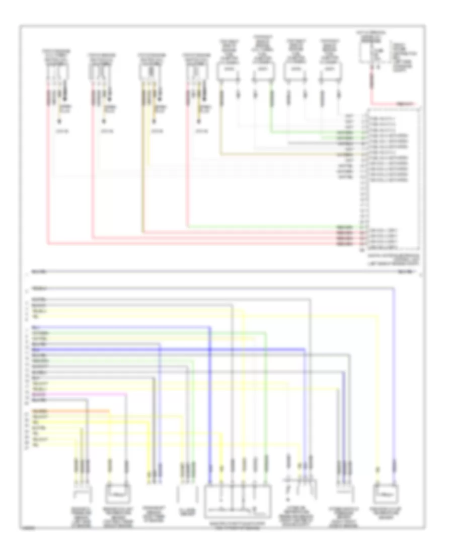
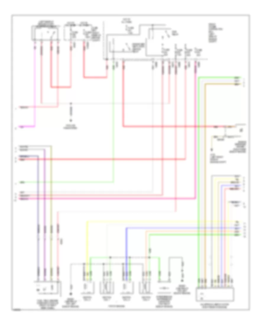
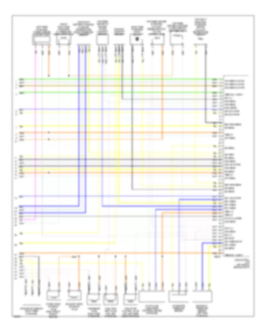
2.0L Turbo, Engine Performance Wiring Diagram (1 of 4) for MINI Cooper S 2014
List of elements for 2.0L Turbo, Engine Performance Wiring Diagram (1 of 4) for MINI Cooper S 2014:
- (right rear of engine) valvetronic actuator motor
- 3b 15 sply
- 3b sig clutch
- 4b act rly
- 8b bus sig
- Accelerator pedal module (part of acceleration pedal assembly)
- Body domain controller
- Brake light switch (left side of left footwell)
- Brk lt sw sig
- Bus sig flexray
- Clutch module (m/t) (under left side of dash)
- Clutch sig
- Computer data lines system
- Cooling fans system
- Cut-out relay
- Digital motor electronics control unit (left side of engine compt)
- Dme main relay
- Electric fan
- Electrical exhaust flap
- Engine strt sig
- Flap activation term 15 wake up sig
- Flexray
- Flexray bus sig
- Fuel inj sply
- Fuel pmp ctrl
- Fuse 10a
- Fuse 15a
- Fuse 20a
- Fuse 40a
- Gnd
- Hall sens gnd
- Hall sens sig
- Hall sens sply
- Hot at all times
- Ign sply
- Ignition & fuel injection relay
- Leak detection sig
- Lin bus sig
- Motor position sensor
- Mtr activation
- Natural vacuum leak detection
- Pnk
- Pressure switch
- Pt-can bus sig
- Red
- Rly activation
- Sens gnd
- Sens sig
- Sens sply
- Spd sig
- Term
- Term 15
- Term 15 sply
- Term 30b sply
- Valvetronic relay
- Vlv sply
- Z10 1b
- Z10 3b
- Z10 7b
- Z10 8b
- Z6000 1b
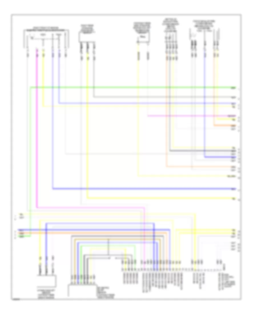
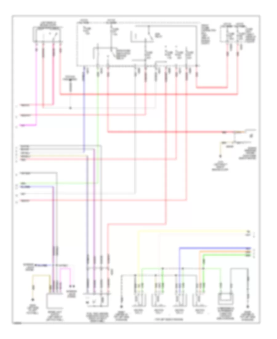
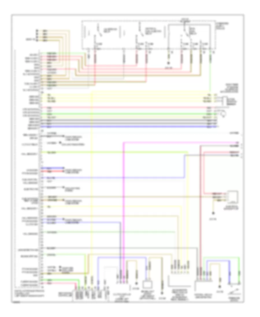
2.0L Turbo, Engine Performance Wiring Diagram (2 of 4) for MINI Cooper S 2014
List of elements for 2.0L Turbo, Engine Performance Wiring Diagram (2 of 4) for MINI Cooper S 2014:
- (2.0l turbo) coolant pump changeover valve
- (2.0l turbo) knock sensor 2
- (right side of engine) knock sensor
- Activation
- Characteristic map thermostat (top rear center of engine)
- Coolant pmp
- Coolant pmp gnd
- Cooling fans system
- Crank sens gnd
- Crank sens sig
- Crank sens sply
- Digital motor electronics control unit (left side of engine compt)
- Elec thr act
- Elec thr act gnd
- Elec thr act sig
- Elec thr act sply
- Front power distribution box (left side of engine compt)
- Fuse 5a
- Gear gnd
- Gear sens sig
- Hot at all times
- Hot w/ terminal 15n relay energized
- Hot w/ terminal 30b relay 1 energized
- Knock sens sig
- Lin bus sig
- Map thrmostat
- Oil lvl sens sig
- Oil lvl sens sply
- Oil press ctrl
- Oil press sig
- Oil pressure control valve
- Press sens sig
- Press sens sply
- Radiator outlet
- Sens gnd
- Sply fuel tank
- Starting/ charging system
- Tank vent valve (top left of engine)
- Temp sens sig
- Thr sens gnd
- Vlv activation
- Vlv sply
- Zero gear sensor (top of transmission)
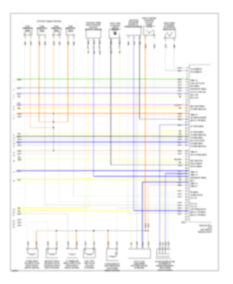
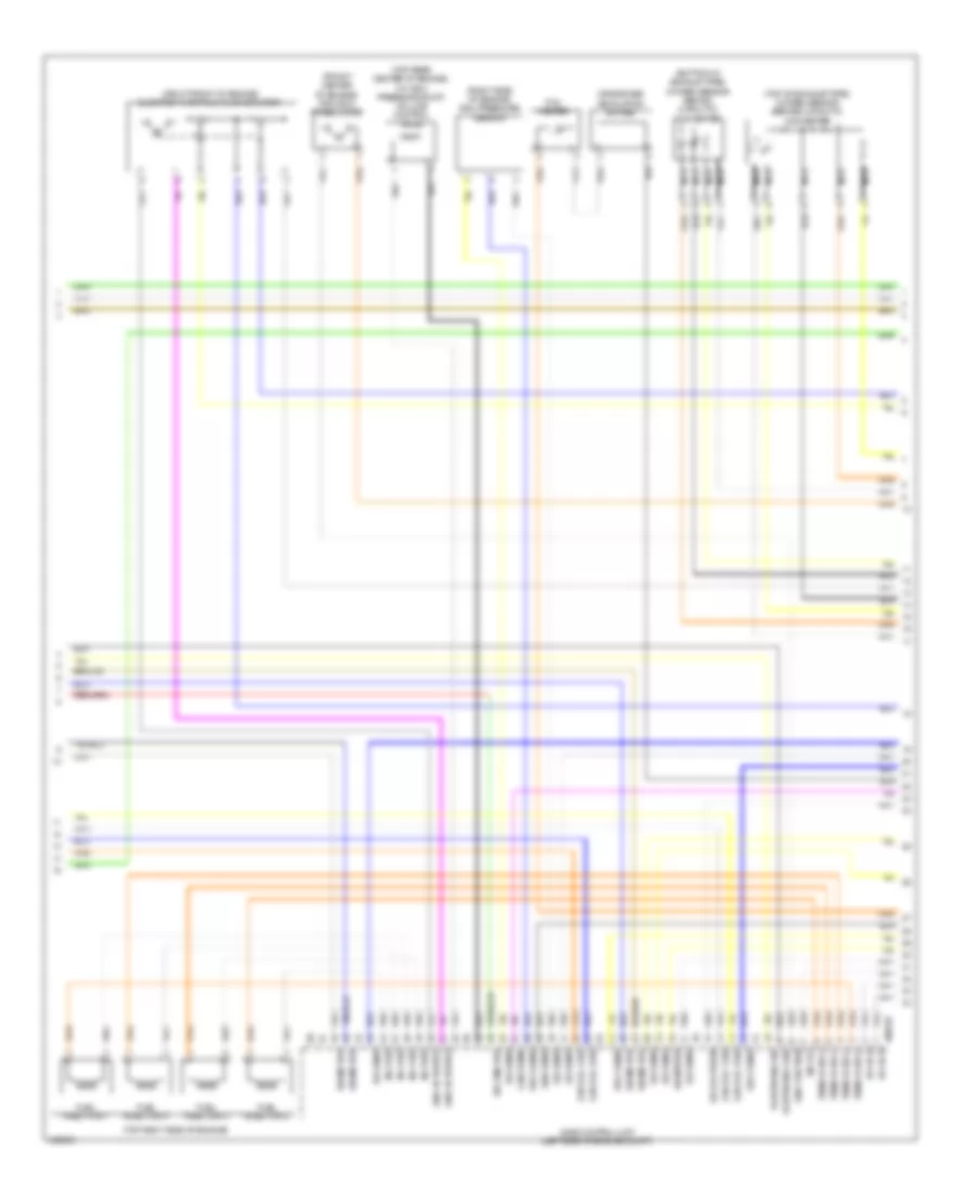
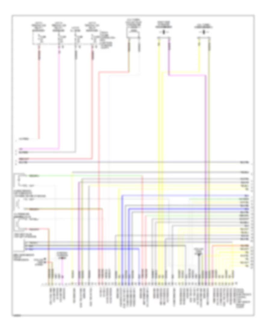
2.0L Turbo, Engine Performance Wiring Diagram (3 of 4) for MINI Cooper S 2014
List of elements for 2.0L Turbo, Engine Performance Wiring Diagram (3 of 4) for MINI Cooper S 2014:
- (top of engine)
- (top of engine) (2.0l turbo) ignition coil cylinder 4
- (top right side of engine) (2.0l turbo) fuel injector cylinder 4
- (top right side of engine) fuel injector cylinder 1
- (top right side of engine) fuel injector cylinder 2
- (top right side of engine) fuel injector cylinder 3
- Crankshaft sensor (right rear of engine)
- Digital motor electronics control unit (left side of engine compt)
- Electric throttle actuator (right front of engine)
- Engine coolant temperature sensor (top right rear side of engine)
- Engine oil pressure sensor (left side of engine)
- Front power distribution box (left side of engine compt)
- Fuel inj 1 activation
- Fuel inj 2 activation
- Fuel inj 3 activation
- Fuel inj 4 activation
- Fuel inj cyl 1
- Fuel inj cyl 2
- Fuel inj cyl 3
- Fuel inj cyl 4
- Fuse 20a
- Hot w/ terminal 30b relay 1 energized
- Ign coil 1 activation
- Ign coil 1 sply
- Ign coil 2 activation
- Ign coil 2 sply
- Ign coil 3 activation
- Ign coil 3 sply
- Ign coil 4 activation
- Ign coil 4 sply
- Ignition coil cylinder 1
- Ignition coil cylinder 2
- Ignition coil cylinder 3
- Intake air temperature pressure sensor (front center of engine compt)
- Intake manifold pressure sensor (right front side of engine)
- Nca
- Oil level sensor
- Radiator outlet temperature sensor
- Spark plug
- Z19 1b
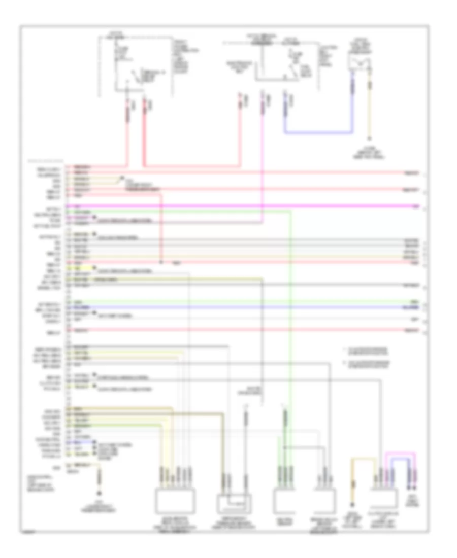
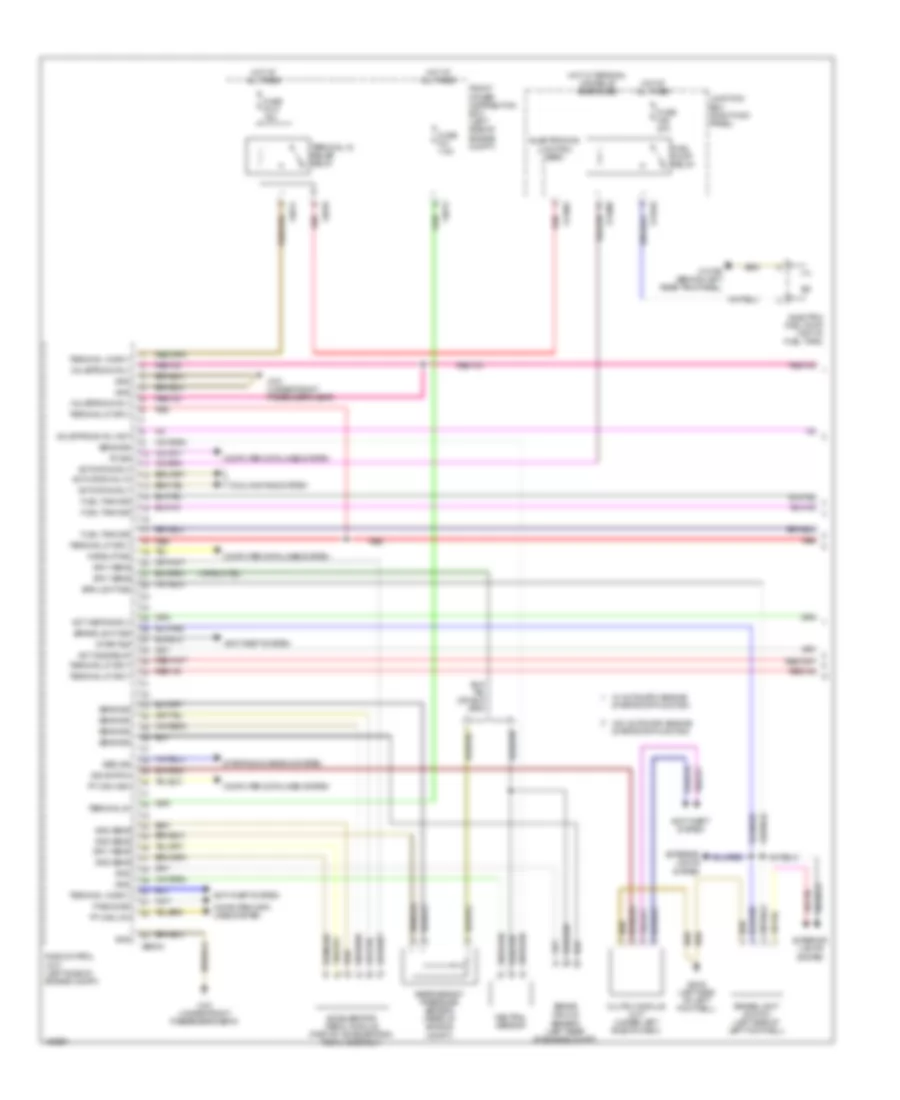
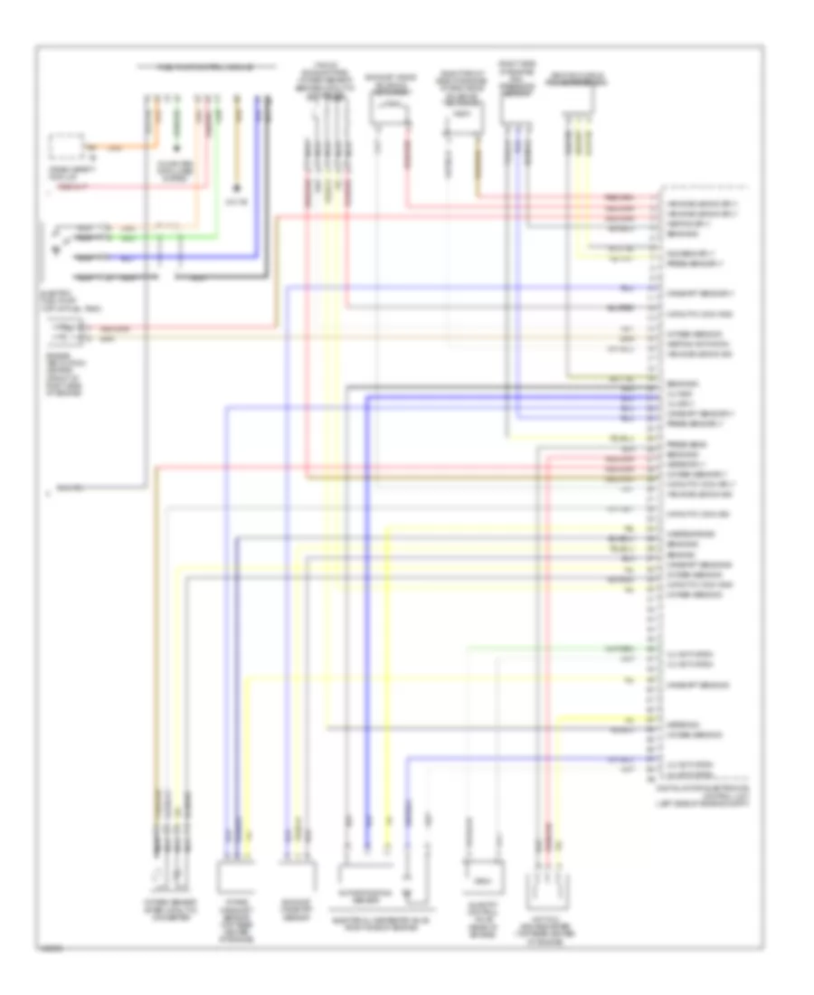
2.0L Turbo, Engine Performance Wiring Diagram (4 of 4) for MINI Cooper S 2014
List of elements for 2.0L Turbo, Engine Performance Wiring Diagram (4 of 4) for MINI Cooper S 2014:
- (right front side of engine) intake vanos solenoid actuator
- (right side of engine) rail pressure sensor
- (top of exhaust pipe) oxygen sensor before catalytic converter
- Camshaft sens gnd
- Camshaft sens sig
- Camshaft sens sply
- Catalytic conv gnd
- Catalytic conv sig
- Catalytic conv sply
- Computer data lines system
- Crash safety module
- Digital motor electronics control unit (left side of engine compt)
- Electric fuel pump (top of fuel tank)
- Electrical wastegate valve (right side of engine)
- Engine ventilation heating (front of right side of engine)
- Exhaust camshaft sensor
- Exhaust vanos solenoid actuator
- Fuel pump control module
- Heating activation
- Heating sply
- Hot film air mass meter (top rear center of engine)
- Intake camshaft sensor (top rear center of engine)
- Meter sig
- Meter sply
- N02 sens sply
- Nca
- Oxygen sens sig
- Oxygen sens sply
- Oxygen sensor after catalytic converter
- Press sens
- Press sens sply
- Quantity control valve (rear of engine)
- Rotor position sensor
- Sens gnd
- Sens sig
- Vanos solenoid sig
- Vanos solenoid sply
- Venturi nozzle pressure sensor
- Vlv activation
- Vlv gnd
- Vlv sply
- Wastegate sig
- Z10 7b