ENGINE PERFORMANCE
3.0L
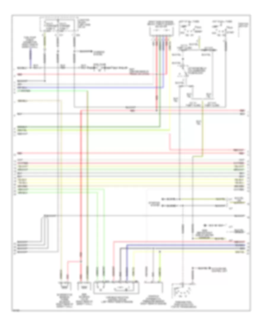
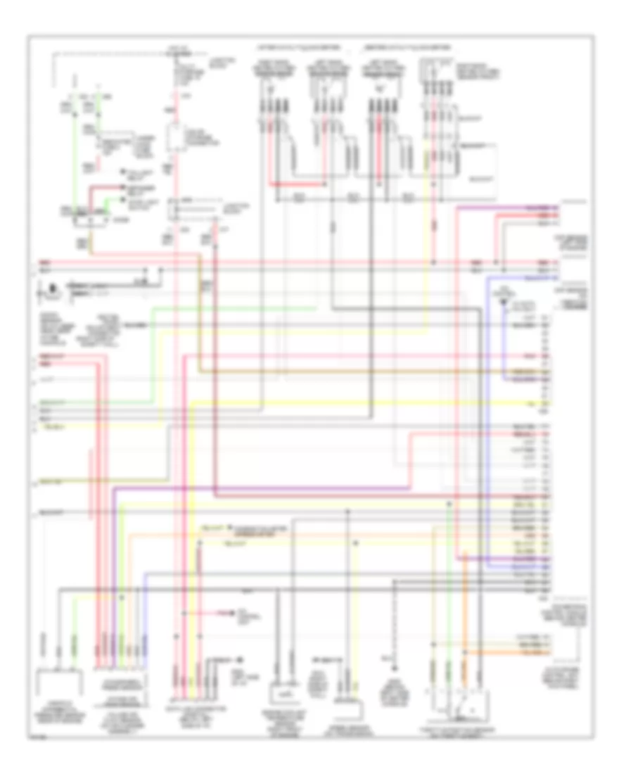
3.0L DOHC Non-Turbo, Engine Performance Wiring Diagrams (1 of 3) for Mitsubishi 3000GT VR-4 1997

List of elements for 3.0L DOHC Non-Turbo, Engine Performance Wiring Diagrams (1 of 3) for Mitsubishi 3000GT VR-4 1997:
- (center of i/p, right of center console) mfi relay i
- (center of i/p, right of center console) mfi relay ii
- (left side of engine)
- B21
- B22
- C46
- C47
- C52
- C53
- Capacitor (right front of engine)
- Check engine indicator (mil)
- Clutch relay
- Combination meter
- Dedicated fuse 1 20a
- Elc-4 a/t control unit (behind center console)
- Engine speed detection connector (right side of safety wall)
- Fuel injectors
- G123 (right side of safety wall)
- G206 (behind right side of center console)
- Hot at all times
- Ignition coil 1-4 (top of engine)
- Ignition coil 2-5 (top of engine)
- Ignition coil 3-6 (top of engine)
- Ignition power transistor (top of engine)
- Magnetic
- Nca
- Power
- Powertrain control module (behind center console)
- Radiator & condenser fan motor relays
- Red
- Spark plugs 1 & 4
- Spark plugs 2 & 5
- Spark plugs 3 & 6
- Steering pressure
- Switch
- Tach
- Thermostat
- Under- hood fuse block
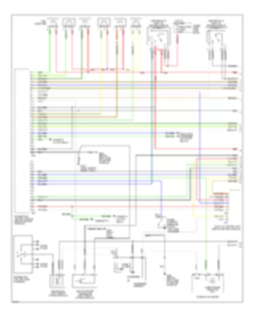
3.0L DOHC Non-Turbo, Engine Performance Wiring Diagrams (2 of 3) for Mitsubishi 3000GT VR-4 1997
List of elements for 3.0L DOHC Non-Turbo, Engine Performance Wiring Diagrams (2 of 3) for Mitsubishi 3000GT VR-4 1997:
- (right side of engine, below throttle body) isc motor
- A/t
- A/t w/ theft alarm
- A/t w/ theft alarm & m/t
- A/t w/o theft alarm
- Acc
- Auto-cruise control unit
- B10
- C71
- C82
- Charging system
- Egr solenoid valve (right rear of safety wall)
- Evaporative emission purge solenoid (right rear of safety wall)
- Fuel pump
- Fuel pump check connector (right side of safety wall)
- G206 (behind right side of center console)
- G407 (center rear of trunk, on latch)
- Hot at all times
- Ig1
- Ig2
- Ignition switch
- Junction block (left side of i/p)
- Lock
- M/t
- Manifold differential pressure sensor (right rear of engine)
- Multi- purpose fuse 11 15a
- Multi- purpose fuse 12 15a
- Nca
- Park/neutral position switch (top of transmission)
- Red
- Run
- Start
- Starter relay (in underhood fuse block)
- Starting system
- Variable induction control motor (left front side of engine)
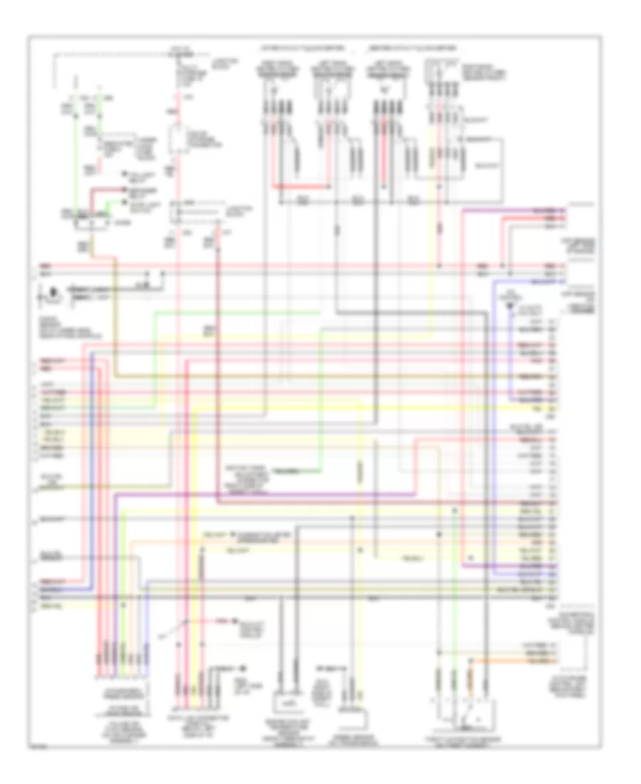
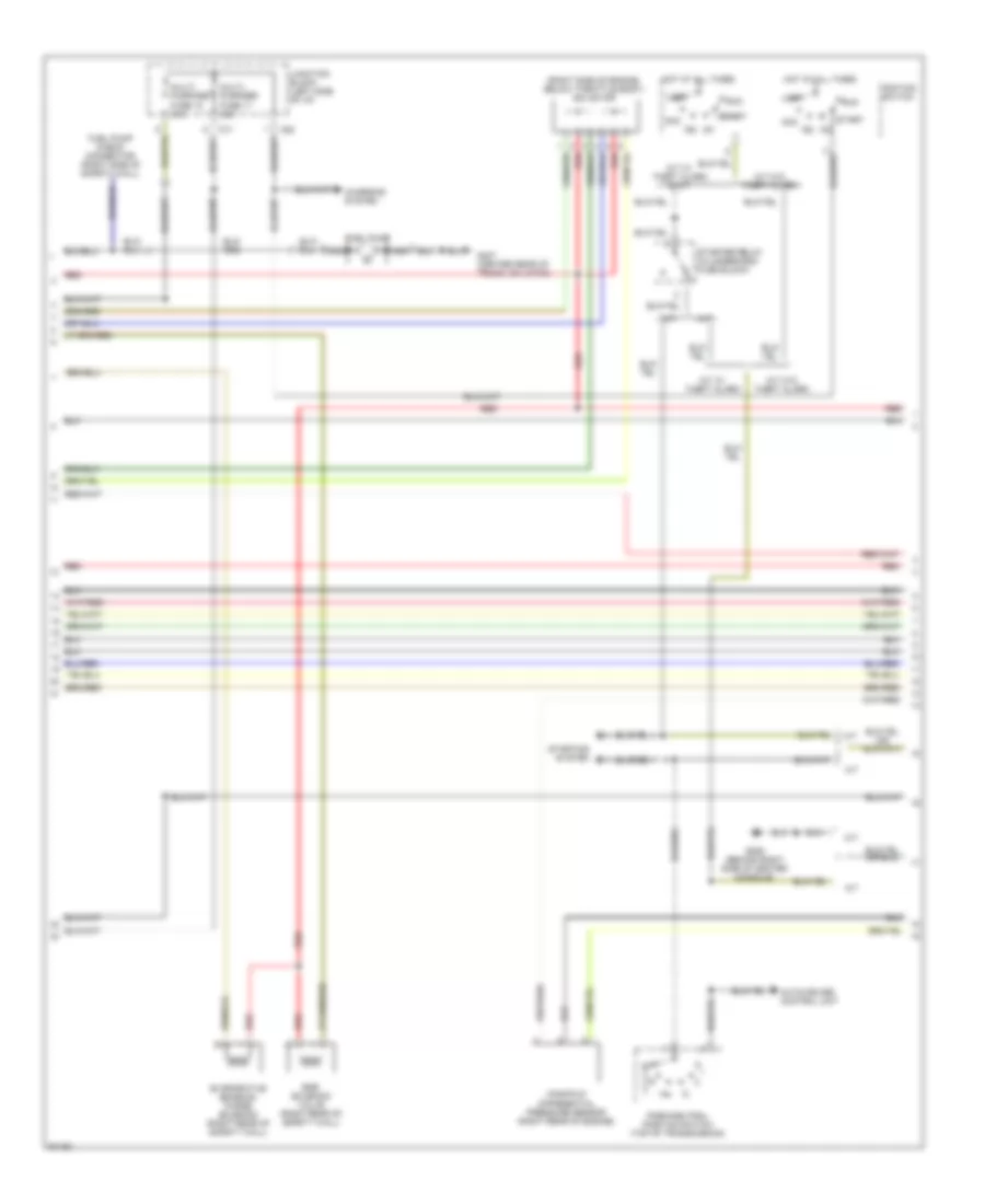
3.0L DOHC Non-Turbo, Engine Performance Wiring Diagrams (3 of 3) for Mitsubishi 3000GT VR-4 1997
List of elements for 3.0L DOHC Non-Turbo, Engine Performance Wiring Diagrams (3 of 3) for Mitsubishi 3000GT VR-4 1997:
- (after catalytic converter)
- (before catalytic converter)
- (right side of
- A/c control unit
- A/t
- Adjustment connector
- Atmospheric press sensor
- Auto-cruise control unit (behind right kick panel)
- C54
- C69
- C70
- C77
- C83
- C92
- Ckp sensor (on vibration damper)
- Cmp sensor (left side of engine)
- Combination meter (speedometer)
- Data link connector (partial) (below left side of i/p)
- Dedicated fuse 2 15a
- Defogger relay
- Diode
- Elc-4 a/t control module
- Engine coolant temperature sensor (near thermostat assembly)
- G123 (right side of safety wall)
- G202 (left side of i/p)
- Heated oxygen sensor (front)
- Hot at all times
- Ignition timing
- Intake air temp sensor
- Iod or storage connector
- Junction block
- Knock sensor (on cylinder head, near intake manifold)
- Left bank heated oxygen sensor (front)
- Left bank heated oxygen sensor (rear)
- Multi- purpose fuse 19 10a
- Nca
- Pnk
- Powertrain control module (behind center console)
- Red
- Right bank
- Right bank heated oxygen sensor (rear)
- Safety wall)
- Speed sensor (on transmission)
- Stop light switch
- Taillight relay
- Throttle position sensor (on throttle body)
- Under- hood fuse block
- Volume air flow sensor (on air cleaner assembly)
- W/ auto a/c only
3.0L DOHC Turbo, Engine Performance Wiring Diagrams (1 of 3) for Mitsubishi 3000GT VR-4 1997
List of elements for 3.0L DOHC Turbo, Engine Performance Wiring Diagrams (1 of 3) for Mitsubishi 3000GT VR-4 1997:
- (center of i/p, right of center console) mfi relay i
- (center of i/p, right of center console) mfi relay ii
- (left side of engine)
- B21
- B22
- C52
- C53
- Capacitor (right front of engine)
- Check engine indicator (mil)
- Clutch relay
- Combination meter
- Dedicated fuse 1 20a
- Engine speed detection connector (right side of safety wall)
- Fuel
- G123 (right side of safety wall)
- G206 (behind right side of center console)
- Hot at all times
- Ignition coil 1-4 (top of engine)
- Ignition coil 2-5 (top of engine)
- Ignition coil 3-6 (top of engine)
- Ignition power transistor (top of engine)
- Injectors
- Magnetic
- Nca
- Power
- Powertrain control module (behind center console)
- Radiator & condenser fan motor relays
- Red
- Resistor (right rear of engine compt)
- Spark plugs 1 & 4
- Spark plugs 2 & 5
- Spark plugs 3 & 6
- Steering pressure
- Switch
- Tach
- Under- hood fuse block
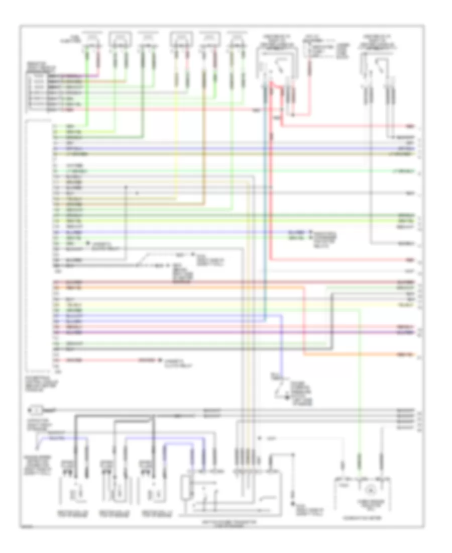
3.0L DOHC Turbo, Engine Performance Wiring Diagrams (2 of 3) for Mitsubishi 3000GT VR-4 1997
List of elements for 3.0L DOHC Turbo, Engine Performance Wiring Diagrams (2 of 3) for Mitsubishi 3000GT VR-4 1997:
- (right side of engine, below throttle body) isc motor
- Acc
- Boost gauge
- C71
- C82
- Charging system
- Egr solenoid valve (right side of safety wall)
- Evaporative emission purge solenoid (right side of safety wall)
- Fuel pressure solenoid (right side of safety wall)
- Fuel pump
- Fuel pump check connector (right side of safety wall)
- Fuel pump circuit resistor (right side of engine compartment)
- Fuel pump relay (near underhood relay box)
- G206 (behind right side of center console)
- Gauge assembly
- Hot at all times
- Ig1
- Ig2
- Ignition switch
- Junction block (left side of i/p)
- Lock
- Multi- purpose fuse 11 15a
- Multi- purpose fuse 12 15a
- Nca
- Red
- Run
- Start
- Starter relay (in underhood fuse block)
- Starting
- System
- Turbocharger waste gate solenoid (right side of safety wall)
3.0L DOHC Turbo, Engine Performance Wiring Diagrams (3 of 3) for Mitsubishi 3000GT VR-4 1997
List of elements for 3.0L DOHC Turbo, Engine Performance Wiring Diagrams (3 of 3) for Mitsubishi 3000GT VR-4 1997:
- (after catalytic converter)
- (before catalytic converter)
- (right side of
- A/c control unit
- Adjustment connector
- Atmospheric press sensor
- Auto-cruise control unit (behind right kick panel)
- C54
- C69
- C70
- C77
- C83
- C92
- Ckp sensor (on vibration damper)
- Cmp sensor (left side of engine)
- Combination meter (speedometer)
- Data link connector (partial) (below left side of i/p)
- Dedicated fuse 2 15a
- Defogger relay
- Diode
- Engine coolant temperature sensor (right front of engine)
- G123 (right side of safety wall)
- G202 (left side of i/p)
- G206 (behind right side of center console)
- Heated oxygen sensor (front)
- Hot at all times
- Ignition
- Intake air temp sensor
- Iod or storage connector
- Junction block
- Knock sensor (on cylinder head, near intake manifold)
- Left bank heated oxygen sensor (front)
- Left bank heated oxygen sensor (rear)
- Manifold differential pressure sensor (rear of engine)
- Multi- purpose fuse 19 10a
- Nca
- Pnk
- Powertrain control module (behind center console)
- Red
- Right bank
- Right bank heated oxygen sensor (rear)
- Safety wall)
- Speed sensor (on transmission)
- Stop light switch
- Taillight relay
- Throttle position sensor (on throttle body)
- Timing
- Under- hood fuse block
- Volume air flow sensor (on air cleaner assembly)
- W/ auto a/c only
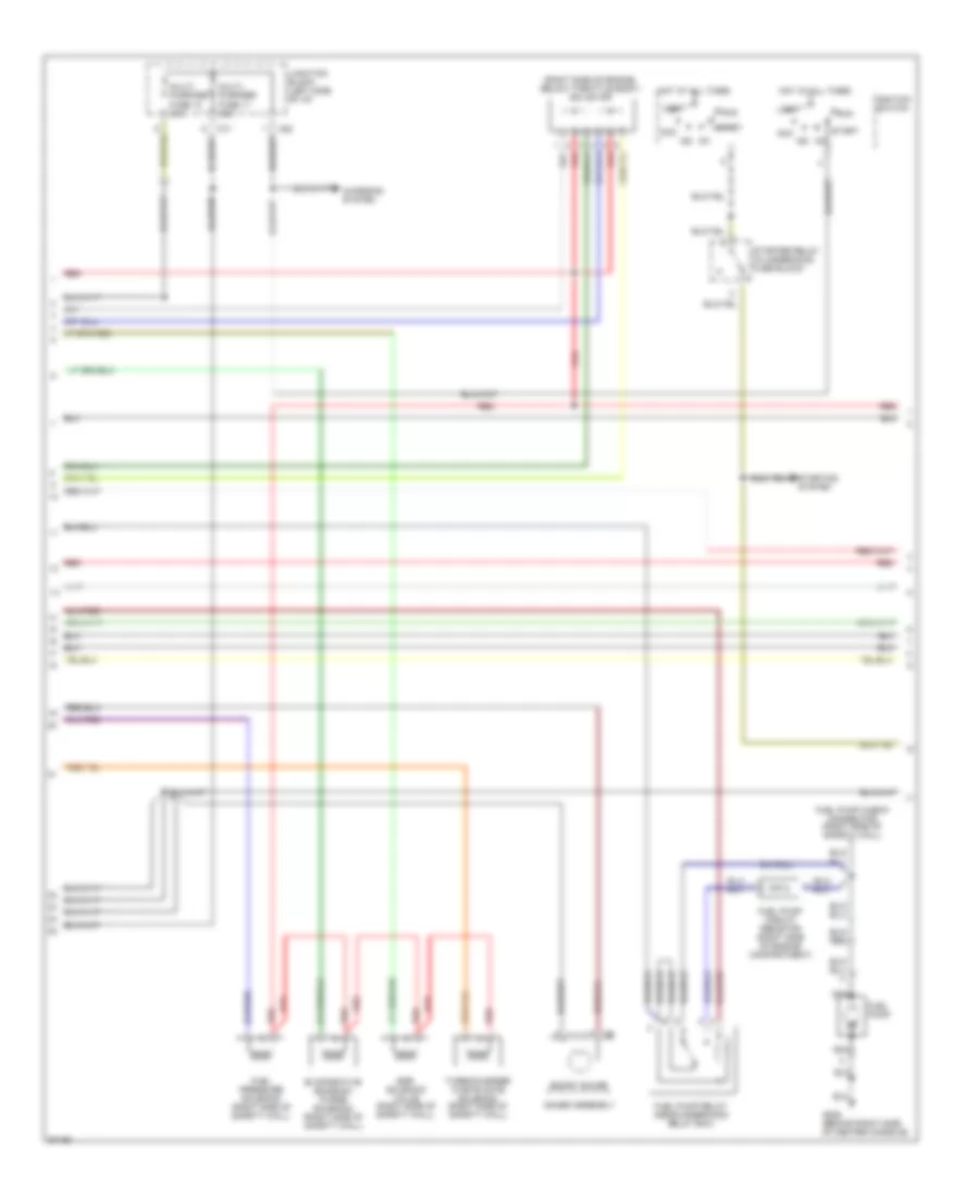
3.0L SOHC, Engine Performance Wiring Diagrams (1 of 3) for Mitsubishi 3000GT VR-4 1997
List of elements for 3.0L SOHC, Engine Performance Wiring Diagrams (1 of 3) for Mitsubishi 3000GT VR-4 1997:
- (center of i/p, right of center console) mfi relay i
- (center of i/p, right of center console) mfi relay ii
- (left side of engine)
- C46
- C47
- C52
- C53
- Check engine indicator (mil)
- Clutch relay
- Coil wire
- Combination meter
- Condenser
- Condenser assembly
- Dedicated fuse 1 20a
- Distributor (top left side of engine)
- Elc-4 a/t control unit (behind center console)
- Fuel injectors
- G123 (right side of safety wall)
- G203 (right kick panel)
- G206 (behind right side of center console)
- Hot at all times
- Ignition coil (left side of intake manifold)
- Ignition power transistor (left side of intake manifold)
- Magnetic
- Noise filter
- Power
- Powertrain control module (behind center console)
- Radiator & condenser fan motor relays
- Red
- Spark plugs
- Steering pressure
- Switch
- Tach
- Thermostat
- Under- hood fuse block
3.0L SOHC, Engine Performance Wiring Diagrams (2 of 3) for Mitsubishi 3000GT VR-4 1997
List of elements for 3.0L SOHC, Engine Performance Wiring Diagrams (2 of 3) for Mitsubishi 3000GT VR-4 1997:
- (right side of engine, below throttle body) isc motor
- A/t
- A/t w/ theft alarm
- A/t w/ theft alarm & m/t
- A/t w/o theft alarm
- Acc
- Auto-cruise control unit
- C71
- C82
- Charging system
- Egr solenoid valve (right rear of safety wall)
- Evaporative emission purge solenoid (right rear of safety wall)
- Fuel pump
- Fuel pump check connector (right side of safety wall)
- G206 (behind right side of center console)
- G407 (center rear of trunk, on latch)
- Hot at all times
- Ig1
- Ig2
- Ignition switch
- Junction block (left side of i/p)
- Lock
- M/t
- Manifold differential pressure sensor (right rear of engine)
- Multi- purpose fuse 11 15a
- Multi- purpose fuse 12 15a
- Nca
- Park/neutral position switch (top of transmission)
- Red
- Run
- Start
- Starter relay (in underhood fuse block)
- Starting system
3.0L SOHC, Engine Performance Wiring Diagrams (3 of 3) for Mitsubishi 3000GT VR-4 1997
List of elements for 3.0L SOHC, Engine Performance Wiring Diagrams (3 of 3) for Mitsubishi 3000GT VR-4 1997:
- (after catalytic converter)
- (before catalytic converter)
- (right side of
- A/c control unit
- A/t
- Adjustment connector
- Atmospheric press sensor
- Auto-cruise control unit (behind right kick panel)
- C54
- C70
- C77
- C83
- C92
- Ckp sensor (on vibration damper)
- Cmp sensor (inside distributor assembly)
- Combination meter (speedometer)
- Data link connector (partial) (below left side of i/p)
- Elc-4 a/t control module
- Engine coolant temperature sensor (near thermostat assembly)
- G123 (right side of safety wall)
- G202 (left side of i/p)
- Heated oxygen sensor (front)
- Hot at all times
- Ignition timing
- Intake air temp sensor
- Iod or storage connector
- Junction block
- Knock sensor (on cylinder head, near intake manifold)
- Left bank heated oxygen sensor (front)
- Left bank heated oxygen sensor (rear)
- Multi- purpose fuse 19 10a
- Nca
- Pnk
- Powertrain control module (behind center console)
- Red
- Right bank
- Right bank heated oxygen sensor (rear)
- Safety wall)
- Speed sensor (on transmission)
- Throttle position sensor (on throttle body)
- Volume air flow sensor (on air cleaner assembly)
- W/ auto a/c only