ENGINE PERFORMANCE
2.4L
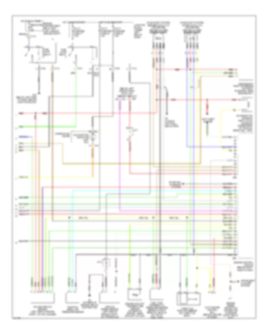
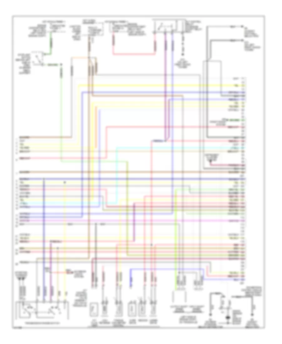
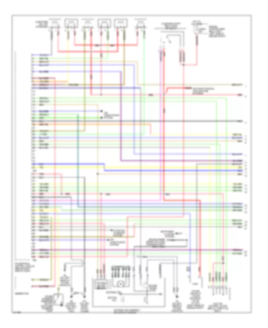
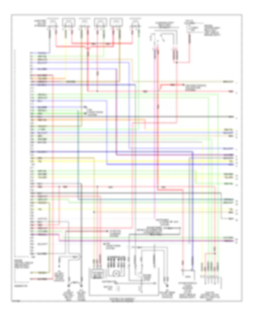
2.4L, Engine Performance Wiring Diagram, with M/T (1 of 2) for Mitsubishi Eclipse Spyder GT 2005

List of elements for 2.4L, Engine Performance Wiring Diagram, with M/T (1 of 2) for Mitsubishi Eclipse Spyder GT 2005:
- (in engine compt relay box) mfi relay
- (on center of engine, below intake manifold)
- (on rear of cylinder head) camshaft position sensor
- Air conditioning & cooling fans system
- Air conditioning system
- C49
- C53
- Capacitor (on rear center of engine)
- Dedicated fuse 9 20a
- Egr solenoid valve
- Engine compartment relay box (left side of engine compt)
- Engine control module (behind right side of dash)
- Evaporative emission purge solenoid
- Fuel pump module
- G13 (on left front shock tower)
- G4 (on rear of engine, below distributor)
- G5 (in right footwell, below ecm)
- G6 (convertible) (on crossmember, below right front front seat belt retractor)
- G6 (coupe) (forward of right front seat belt retractor)
- Generator
- Hot at all times
- Idle air control motor (below throttle body)
- Ignition coil 1 (on top front of engine)
- Ignition coil 2 (top front of engine)
- Injectors (right side of engine)
- Instrument cluster system
- Knock sensor (on side of engine block)
- Nca
- Power steering pressure switch (on power steering pump)
- Red
- Spark plugs
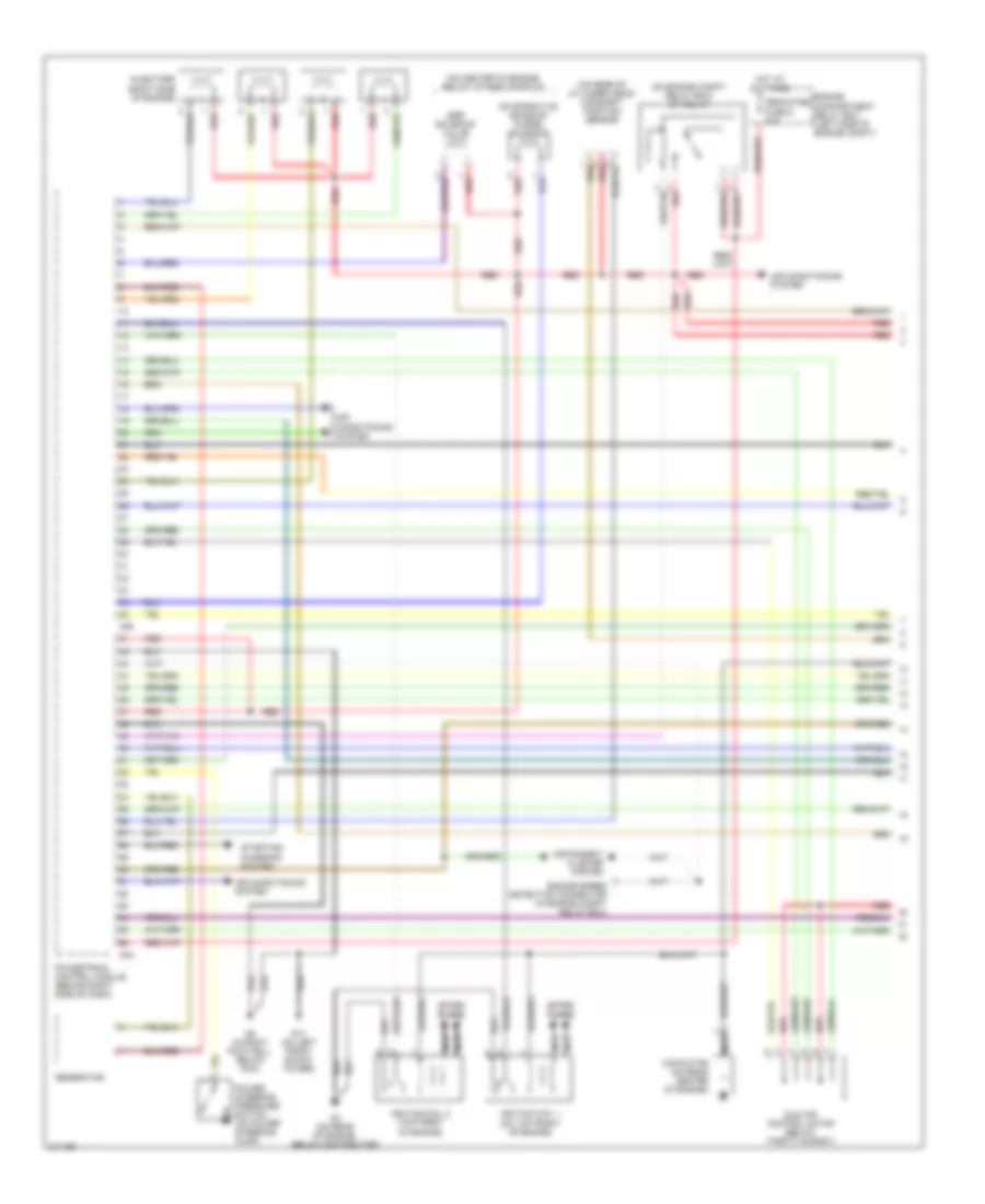
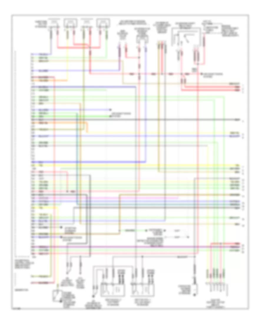
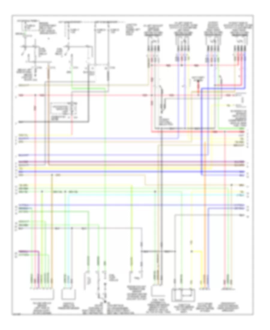
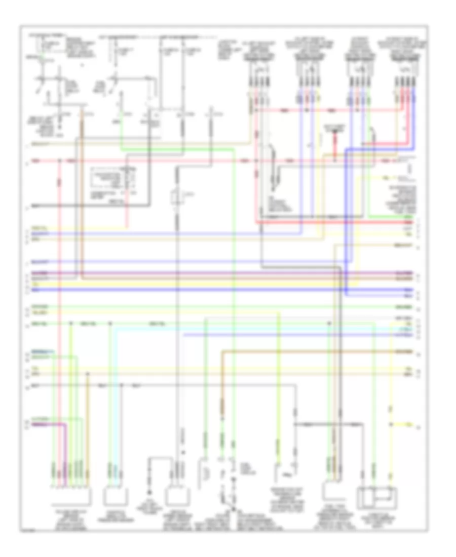
2.4L, Engine Performance Wiring Diagram, with M/T (2 of 2) for Mitsubishi Eclipse Spyder GT 2005
List of elements for 2.4L, Engine Performance Wiring Diagram, with M/T (2 of 2) for Mitsubishi Eclipse Spyder GT 2005:
- (below left side of dash) data link connector (dlc)
- (in exhaust system, after catalytic converter) heated oxygen sensor (rear)
- (in exhaust system, before catalytic converter) heated oxygen sensor (front)
- Anti-theft system
- Auto cruise control ecu (behind center of dash)
- C101
- C108
- C112
- C29
- C30
- C41
- C56
- C60
- Combination meter
- Crankshaft position sensor (on front of engine, near crankshaft)
- Dedicated 15a
- Engine compartment relay box (left side of engine compt)
- Engine control module (behind right side of dash)
- Engine coolant temperature sensor (on rear of engine, near coolant outlet)
- Engine speed detection connector (in engine compt relay box)
- Evaporative emission ventilation solenoid (under rear of vehicle, near fuel tank)
- Fuel pump relay
- Fuel tank differential pressure sensor (beneath right rear of vehicle, on top of fuel tank)
- G15 (below left side of dash, behind junction block)
- G4 (on rear of engine, below distributor)
- G5 (in right footwell, below ecm)
- Hot at all times
- Hot in on or start
- Instrument cluster system
- J/c 1
- J/c 2
- Junction block (under left end of dash)
- Malfunction indicator lamp (mil)
- Manifold absolute pressure sensor
- Multi- purpose fuse 17 7.5a
- Multi- purpose fuse 23 7.5a
- Multi- purpose fuse 24 10a
- Nca
- Red
- Starting/ charging system
- Throttle position sensor (on throttle body)
- Vehicle speed sensor (left side of engine compt, on transaxle)
- Volume airflow sensor (left side of engine compt, on air cleaner)
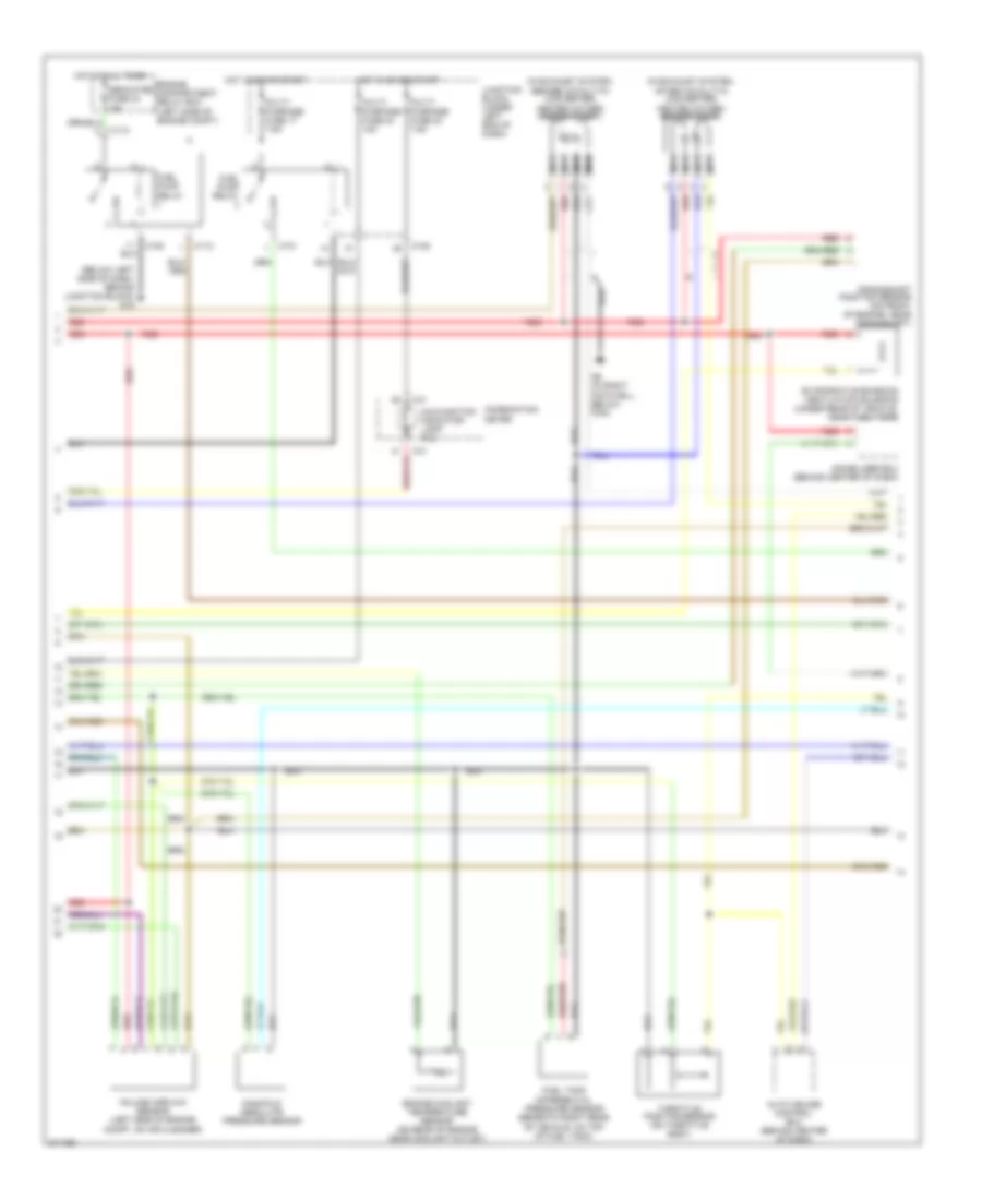
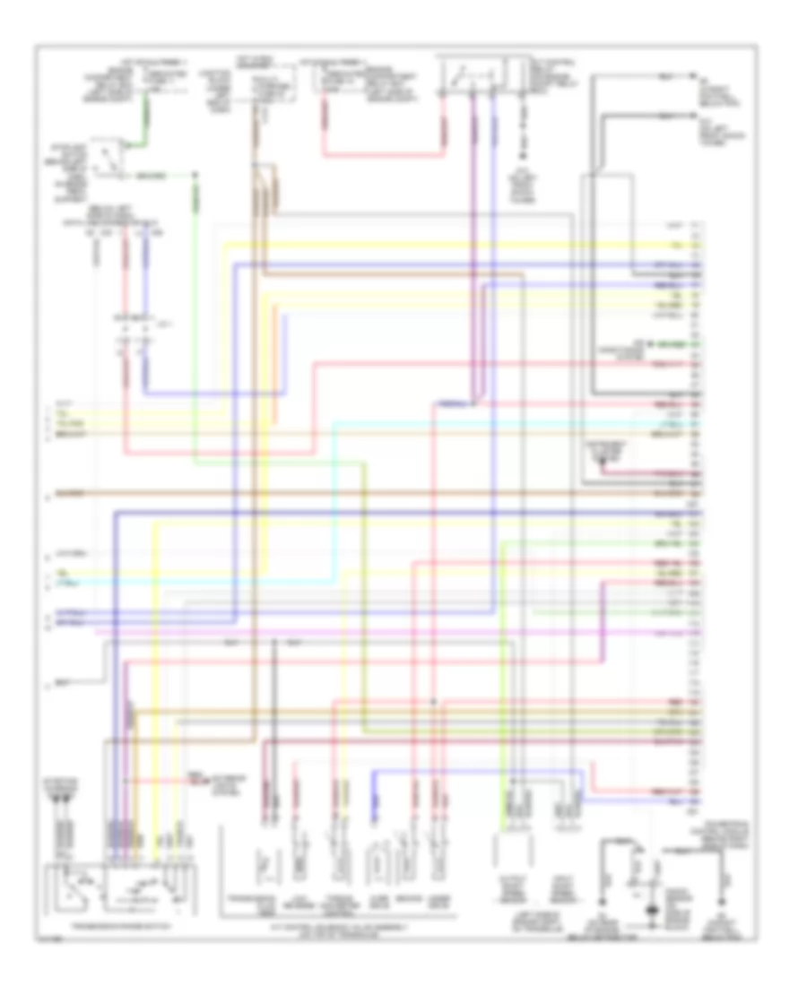
2.4L, Engine Performance Wiring Diagram, with Sportronic (1 of 4) for Mitsubishi Eclipse Spyder GT 2005
List of elements for 2.4L, Engine Performance Wiring Diagram, with Sportronic (1 of 4) for Mitsubishi Eclipse Spyder GT 2005:
- (on center of engine, below intake manifold)
- (on engine compt relay box) mfi relay
- (on rear of cylinder head) camshaft position sensor
- Air conditioning system
- C50
- C54
- Capacitor (on rear center of engine)
- Dedicated fuse 9 20a
- Egr solenoid valve
- Engine compartment relay box (left side of engine compt)
- Engine speed detection connector (in engine compt relay box)
- Evaporative emission purge solenoid
- G13 (on left front shock tower)
- G4 (on rear of engine, below distributor)
- G5 (in right footwell, below pcm)
- Generator
- Hot at all times
- Idle air control motor (below throttle body)
- Ignition coil 1 (on top front of engine)
- Ignition coil 2 (top front of engine)
- Injectors (right side of engine)
- Instrument cluster system
- Nca
- Power steering pressure switch (on power steering pump)
- Powertrain control module (behind right side of dash)
- Red
- Spark plugs
- Starting/ charging system
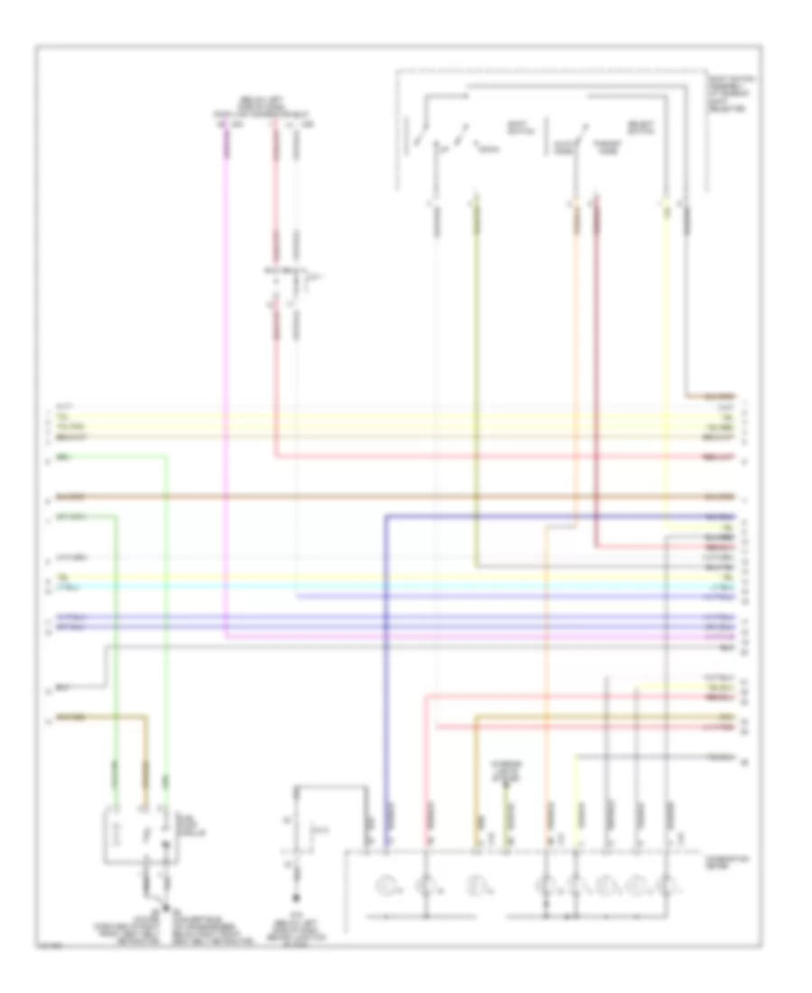
2.4L, Engine Performance Wiring Diagram, with Sportronic (2 of 4) for Mitsubishi Eclipse Spyder GT 2005
List of elements for 2.4L, Engine Performance Wiring Diagram, with Sportronic (2 of 4) for Mitsubishi Eclipse Spyder GT 2005:
- (below left side of dash, behind junction block) g15
- (in exhaust system, after catalytic converter) heated oxygen sensor (rear)
- (in exhaust system, before catalytic converter) heated oxygen sensor (front)
- Auto cruise control ecu (behind center of dash)
- C101
- C108
- C112
- C41
- Combination meter
- Crankshaft position sensor (on front of engine, near crankshaft)
- Dedicated fuse 24 15a
- Engine compartment relay box (left side of engine compt)
- Engine coolant temperature sensor (on rear of engine near coolant outlet)
- Evaporative emission ventilation solenoid (under rear of vehicle, near fuel tank)
- Fuel pump relay
- Fuel tank differential pressure sensor (beneath right rear of vehicle, on top of fuel tank)
- G5 (in right footwell, below pcm)
- Hot at all times
- Hot in on or start
- Immobilizer ecu (behind center of dash)
- Junction block (under left end of dash)
- Malfunction indicator lamp (mil)
- Manifold absolute pressure sensor
- Multi- purpose fuse 17 7.5a
- Multi- purpose fuse 23 7.5a
- Multi- purpose fuse 24 10a
- Nca
- Red
- Throttle position sensor (on throttle body)
- Volume airflow sensor (left side of engine compt, on air cleaner)
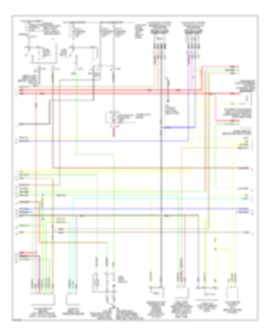
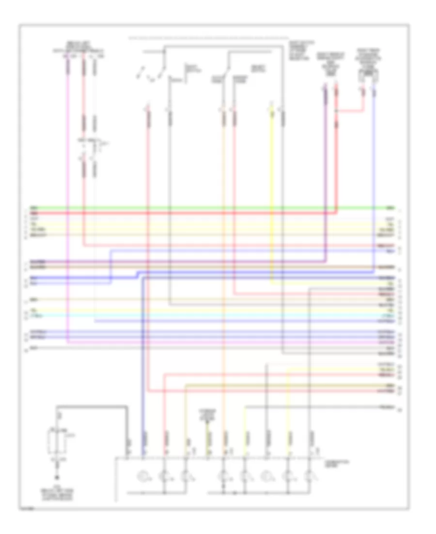
2.4L, Engine Performance Wiring Diagram, with Sportronic (3 of 4) for Mitsubishi Eclipse Spyder GT 2005
List of elements for 2.4L, Engine Performance Wiring Diagram, with Sportronic (3 of 4) for Mitsubishi Eclipse Spyder GT 2005:
- (below left side of dash) data link connector (dlc)
- Auto mode
- C29
- C30
- C41
- C43
- Combination meter
- Down
- Fuel pump module
- G15 (below left side of dash, behind junction block)
- G6 (convertible) (on crossmember, below right front seat belt retractor)
- G6 (coupe) (forward of right front seat belt retractor)
- Interior lights system
- J/c 1
- J/c 2
- Select switch
- Shift switch
- Shift switch assembly (at base of shift selector)
- Sport mode
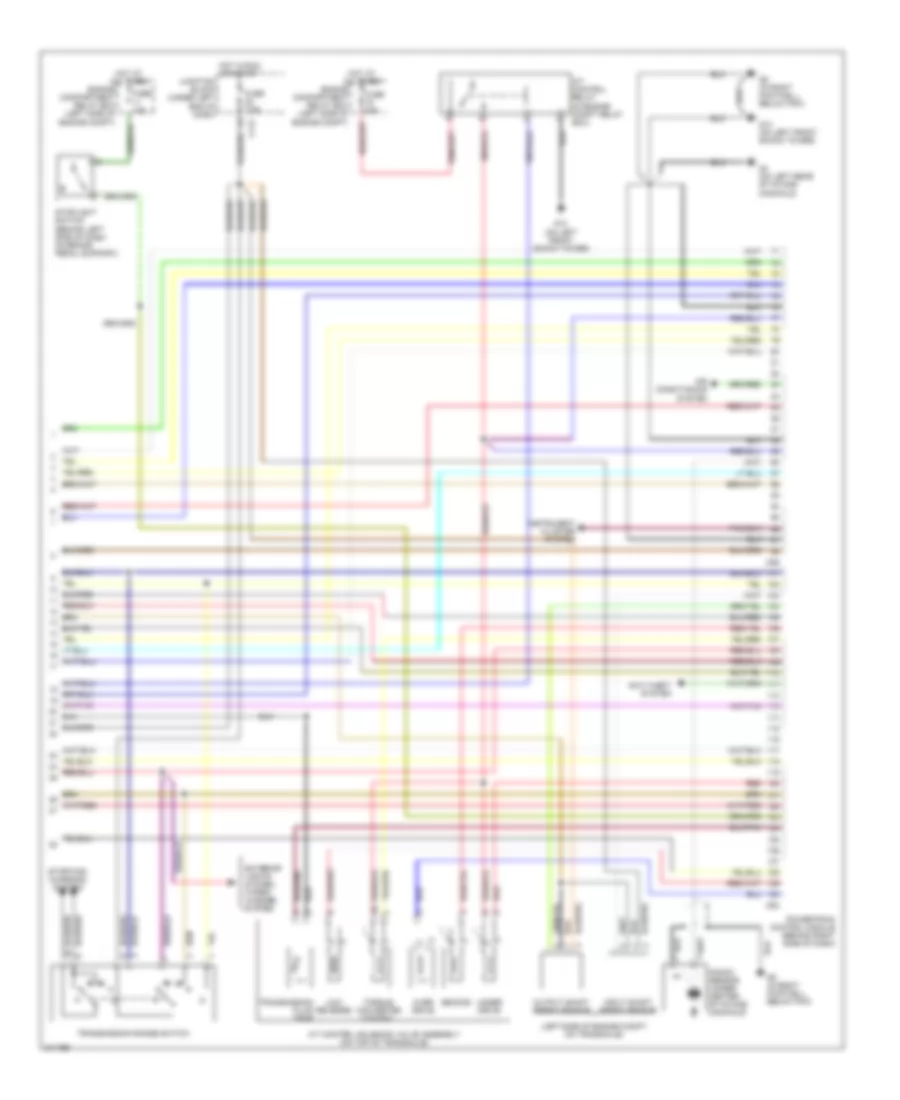
2.4L, Engine Performance Wiring Diagram, with Sportronic (4 of 4) for Mitsubishi Eclipse Spyder GT 2005
List of elements for 2.4L, Engine Performance Wiring Diagram, with Sportronic (4 of 4) for Mitsubishi Eclipse Spyder GT 2005:
- (left side of engine compt, on transaxle)
- A/t control relay (in engine compt relay box)
- A/t control solenoid valve assembly (on top of transaxle)
- A/t fluid temp
- Air conditioning system
- C112
- C57
- C61
- Dedicated fuse 11 15a
- Dedicated fuse 15 20a
- Engine compartment relay box (left side of engine compt)
- Exterior lights system
- G13 (on left front shock tower)
- G4 (on rear of engine, below distributor)
- G5 (in right footwell below pcm)
- G5 (in right footwell, below pcm)
- Hot at all times
- Hot in run or start
- Input shaft speed sensor
- Instrument cluster system
- Junction block (under left end of dash)
- Knock sensor (on side of engine block)
- Low/ reverse
- Multi- purpose fuse 22 7.5a
- Output shaft speed sensor
- Over drive
- Powertrain control module (behind right side of dash)
- Red
- Second
- Starting/ charging system
- Stoplight switch (behind left side of dash, on brake pedal support)
- Torque converter control
- Transmission range switch
- Under drive
2.4L, Engine Performance Wiring Diagram, without Sportronic (1 of 3) for Mitsubishi Eclipse Spyder GT 2005
List of elements for 2.4L, Engine Performance Wiring Diagram, without Sportronic (1 of 3) for Mitsubishi Eclipse Spyder GT 2005:
- (on center of engine, below intake manifold)
- (on engine compt relay box) mfi relay
- (on rear of cylinder head) camshaft position sensor
- Air conditioning system
- C50
- C54
- Capacitor (on rear center of engine)
- Dedicated fuse 9 20a
- Egr solenoid valve
- Engine compartment relay box (left side of engine compt)
- Engine speed detection connector (in engine compt relay box)
- Evaporative emission purge solenoid
- G13 (on left front shock tower)
- G4 (on rear of engine, below distributor)
- G5 (in right footwell, below pcm)
- Generator
- Hot at all times
- Idle air control motor (below throttle body)
- Ignition coil 1 (on top front of engine)
- Ignition coil 2 (top front of engine)
- Injectors (on top of engine)
- Instrument cluster system
- Nca
- Power steering pressure switch (on power steering pump)
- Powertrain control module (behind right side of dash)
- Red
- Spark plugs
- Starting/ charging system
2.4L, Engine Performance Wiring Diagram, without Sportronic (2 of 3) for Mitsubishi Eclipse Spyder GT 2005
List of elements for 2.4L, Engine Performance Wiring Diagram, without Sportronic (2 of 3) for Mitsubishi Eclipse Spyder GT 2005:
- (below left side of dash, behind junction block) g15
- (in exhaust system, after catalytic converter) heated oxygen sensor (rear)
- (in exhaust system, before catalytic converter) heated oxygen sensor (front)
- Auto cruise control ecu (behind center of dash)
- C101
- C108
- C112
- C41
- Combination meter
- Crankshaft position sensor (on front of engine, near crankshaft)
- Dedicated fuse 24 15a
- Engine compartment relay box (left side of engine compt)
- Engine coolant temperature sensor (on rear of engine, near coolant outlet)
- Evaporative emission ventilation solenoid (under rear of vehicle, near fuel tank)
- Fuel pump module
- Fuel pump relay
- Fuel tank differential pressure sensor (beneath right rear of vehicle, on top of fuel tank)
- G5 (in right footwell, below pcm)
- G6 (convertible) (on crossmember, below right front seat belt retractor)
- G6 (coupe) (forward of right front seat belt retractor)
- Hot at all times
- Hot in on or start
- Immobilizer ecu (behind center of dash)
- Junction block (under left end of dash)
- Malfunction indicator lamp (mil)
- Manifold absolute pressure sensor
- Multi- purpose fuse 17 7.5a
- Multi- purpose fuse 23 7.5a
- Multi- purpose fuse 24 10a
- Nca
- Red
- Throttle position sensor (on throttle body)
- Volume airflow sensor (left side of engine compt, on air cleaner)
2.4L, Engine Performance Wiring Diagram, without Sportronic (3 of 3) for Mitsubishi Eclipse Spyder GT 2005
List of elements for 2.4L, Engine Performance Wiring Diagram, without Sportronic (3 of 3) for Mitsubishi Eclipse Spyder GT 2005:
- (below left side of dash) data link connector (dlc)
- (left side of engine compt, on transaxle)
- A/t control relay (on engine compt relay box)
- A/t control solenoid valve assembly (on top of transaxle)
- Air conditioning system
- C112
- C29
- C30
- C57
- C61
- Dedicated fuse 11 15a
- Dedicated fuse 15 20a
- Engine compartment relay box (left side of engine compt)
- Exterior lights system
- G13 (on left front shock tower)
- G4 (on rear of engine, below distributor)
- G5 (in right footwell, below pcm)
- Hot at all times
- Hot in run or start
- Input shaft speed sensor
- Instrument cluster system
- J/c 1
- Junction block (under left end of dash)
- Knock sensor (on side of engine block)
- Low/ reverse
- Multi- purpose fuse 22 7.5a
- Output shaft speed sensor
- Over drive
- Powertrain control module (behind right side of dash)
- Red
- Second
- Starting/ charging system
- Stoplight switch (behind left side of dash, on brake pedal support)
- Torque converter control
- Transmission fluid temp
- Transmission range switch
- Under drive
3.0L
3.0L, Engine Performance Wiring Diagram, with A/T (1 of 4) for Mitsubishi Eclipse Spyder GT 2005
List of elements for 3.0L, Engine Performance Wiring Diagram, with A/T (1 of 4) for Mitsubishi Eclipse Spyder GT 2005:
- (in engine compt relay box) mfi relay
- Air conditioning & cooling fans systems
- Air conditioning system
- C52
- C55
- Detection conn (in engine compt relay box)
- Distributor
- Distributor assembly (on rear of engine)
- Engine compartment relay box (left side of engine compt)
- Engine speed
- Fuse 9 20a
- G13 (on left front shock tower)
- G4 (on left rear of intake manifold)
- G5 (in right footwell, below pcm)
- Generator
- Hot at all times
- Idle air control motor (below throttle body)
- Ignition coil
- Injectors (on top of engine)
- Instrument cluster system
- Intake manifold tuning solenoid valve (w/ imt) (right rear of engine compt)
- Nca
- Power steering pressure switch (on power steering pump)
- Power trans- istor
- Powertrain control module (behind right side of dash)
- Red
- Starting/ charging system
- To spark plugs
- Top dead center sensor
3.0L, Engine Performance Wiring Diagram, with A/T (2 of 4) for Mitsubishi Eclipse Spyder GT 2005
List of elements for 3.0L, Engine Performance Wiring Diagram, with A/T (2 of 4) for Mitsubishi Eclipse Spyder GT 2005:
- (in left exhaust manifold) left bank heated oxygen sensor (front)
- (in left side of exhaust system, after catalytic converter) left bank heated oxygen sensor (rear)
- (in right exhaust manifold) right bank heated oxygen sensor (front)
- (in right side of exhaust system, after catalytic converter)
- Anti-theft system
- Auto cruise control ecu (behind center of dash)
- C101
- C108
- C112
- C41
- Combination meter
- Crankshaft position sensor (near crankshaft sprocket)
- Engine compartment relay box (left side of engine compt)
- Engine coolant temperature sensor (on rear center of engine, near coolant outlet)
- Evaporative emission ventilation solenoid (under rear of vehicle, near fuel tank)
- Fuel pump module
- Fuel pump relay
- Fuel tank differential pressure sensor (beneath right rear of vehicle, on top of fuel tank)
- Fuse 17 7.5a
- Fuse 23 7.5a
- Fuse 24 10a
- Fuse 24 15a
- G15
- G5 (in right footwell, below pcm)
- G6 (convertible) (on crossmember, below right front seat belt retractor)
- G6 (coupe) (forward of right front seat belt retractor)
- Hot at all times
- Hot in on or start
- Junction block (under left end of dash)
- Malfunction indicator lamp (mil)
- Manifold absolute pressure sensor
- Nca
- Pnk
- Red
- Right bank heated oxygen sensor (rear)
- Throttle position sensor (on throttle body)
- Volume airflow sensor (left side of engine compt, on air cleaner)
3.0L, Engine Performance Wiring Diagram, with A/T (3 of 4) for Mitsubishi Eclipse Spyder GT 2005
List of elements for 3.0L, Engine Performance Wiring Diagram, with A/T (3 of 4) for Mitsubishi Eclipse Spyder GT 2005:
- (below left side of dash) data link connector (dlc)
- (right rear of engine compt) egr solenoid valve
- (right rear of engine) evaporative emission purge solenoid
- Auto mode
- C29
- C30
- C41
- C43
- C78
- Combination meter
- Down
- G15 (below left side of dash, behind junction block)
- Interior lights system
- J/c 1
- J/c 2
- Red
- Select switch
- Shift switch
- Shift switch assembly (at base of shift selector)
- Sport mode
3.0L, Engine Performance Wiring Diagram, with A/T (4 of 4) for Mitsubishi Eclipse Spyder GT 2005
List of elements for 3.0L, Engine Performance Wiring Diagram, with A/T (4 of 4) for Mitsubishi Eclipse Spyder GT 2005:
- (left side of engine compt, on transaxle)
- A/t control relay (in engine compt relay box)
- A/t control solenoid valve assembly (on top of transaxle)
- Air conditioning system
- Anti-theft system
- C112
- C59
- C63
- Engine compartment relay box (left side of engine compt)
- Exterior lights system, wiper/ washer system
- Fuse 15a
- Fuse 20a
- Fuse 7.5a
- G13 (on left front shock tower)
- G4 (on left rear of intake manifold)
- G5 (in right footwell, below pcm)
- Hot at all times
- Hot in run or start
- Input shaft speed sensor
- Instrument cluster system
- Junction block (under left end of dash)
- Knock sensor (under center of intake manifold)
- Low/ reverse
- Output shaft speed sensor
- Over drive
- Powertrain control module (behind right side of dash)
- Red
- Second
- Starting/ charging system
- Stoplight switch (behind left side of dash, on brake pedal support)
- Torque converter control
- Transmission fluid temp
- Transmission range switch
- Under drive
3.0L, Engine Performance Wiring Diagram, with M/T (1 of 3) for Mitsubishi Eclipse Spyder GT 2005
List of elements for 3.0L, Engine Performance Wiring Diagram, with M/T (1 of 3) for Mitsubishi Eclipse Spyder GT 2005:
- (in engine compt relay box) mfi relay
- Air conditioning & cooling fans systems
- Air conditioning system
- C51
- C58
- Detection connector (in engine compt relay box)
- Distributor
- Distributor assembly (on rear of engine)
- Engine compartment relay box (left side of engine compt)
- Engine control module (behind right side of dash)
- Engine speed
- Fuse 9 20a
- G13 (on left front shock tower)
- G4 (on left rear of intake manifold)
- G5 (in right footwell, below ecm)
- Generator
- Hot at all times
- Idle air control motor (below throttle body)
- Ignition coil
- Injectors (on top of engine)
- Instrument cluster system
- Intake manifold tuning solenoid valve (w/ imt) (right rear of engine compt)
- Nca
- Power trans- istor
- Red
- Starting/ charging system
- To spark plugs
- Top dead center sensor
3.0L, Engine Performance Wiring Diagram, with M/T (2 of 3) for Mitsubishi Eclipse Spyder GT 2005
List of elements for 3.0L, Engine Performance Wiring Diagram, with M/T (2 of 3) for Mitsubishi Eclipse Spyder GT 2005:
- (below left side of dash, behind junction block)
- (in left exhaust manifold) left bank heated oxygen sensor (front)
- (in left side of exhaust system, after catalytic converter) left bank heated oxygen sensor (rear)
- (in right exhaust manifold) right bank heated oxygen sensor (front)
- (in right side of exhaust system, after catalytic converter) right bank
- Anti-theft systems
- C101
- C108
- C112
- C41
- Combination meter
- Engine compartment relay box (left side of engine compt)
- Engine coolant temperature sensor (on rear center of engine, near coolant outlet)
- Evaporative emission ventilation solenoid (under rear of vehicle, near fuel tank)
- Fuel pump module
- Fuel pump relay
- Fuel tank differential pressure sensor (beneath right rear of vehicle, on top of fuel tank)
- Fuse 17 7.5a
- Fuse 23 7.5a
- Fuse 24 10a
- Fuse 24 15a
- G13 (on left front shock tower)
- G15
- G5 (in right footwell, below ecm)
- G6 (convertible) (on crossmember, below right front seat belt retractor)
- G6 (coupe) (forward of right front seat belt retractor)
- Heated oxygen sensor (rear)
- Hot at all times
- Hot in on or start
- J/c 2
- Junction block (under left end of dash)
- Malfunction indicator lamp (mil)
- Manifold absolute pressure sensor
- Nca
- Pnk
- Red
- Throttle position sensor (on throttle body)
- Vehicle speed sensor (left side of engine compt, on transaxle)
- Volume airflow sensor (left side of engine compt, on air cleaner)
3.0L, Engine Performance Wiring Diagram, with M/T (3 of 3) for Mitsubishi Eclipse Spyder GT 2005
List of elements for 3.0L, Engine Performance Wiring Diagram, with M/T (3 of 3) for Mitsubishi Eclipse Spyder GT 2005:
- (below left side of dash) data link connector (dlc)
- (in right rear corner of engine compt) egr solenoid valve
- (in right rear corner of engine compt) evaporative emission purge solenoid
- Air conditioning system
- Anti-theft system (immobilizer ecu)
- Auto cruise control ecu (behind center of dash)
- C29
- C30
- C62
- Crankshaft position sensor (near crankshaft sprocket)
- Engine control module (behind right side of dash)
- G5 (in right footwell, below ecm)
- Instrument cluster system
- J/c 1
- Knock sensor (under center of intake manifold)
- Power steering pressure switch (on power steering pump)
- Red