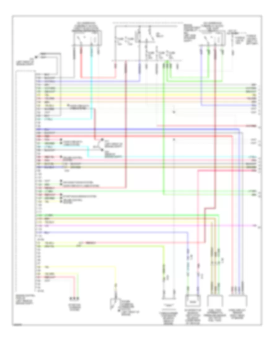
ENGINE PERFORMANCE
2.0L
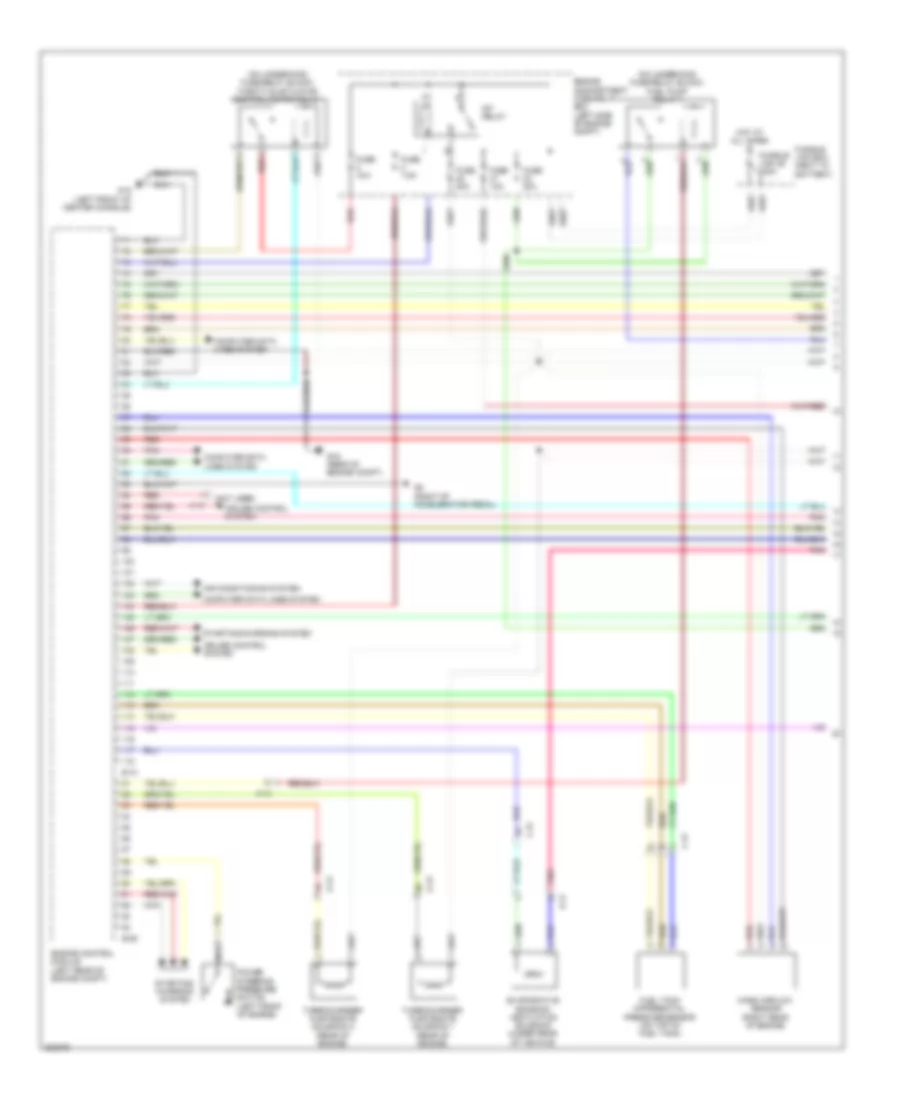
2.0L, Engine Performance Wiring Diagram (1 of 4) for Mitsubishi Lancer GT 2012

List of elements for 2.0L, Engine Performance Wiring Diagram (1 of 4) for Mitsubishi Lancer GT 2012:
- (on underhood fuse/relay block) throttle actuator control motor relay
- A-10
- Air conditioning system
- B-108
- B-109
- C-39
- Computer data lines system
- Cruise control system
- D-14
- Engine compartment fuse/relay box (left side of engine compt)
- Engine control module (left rear of engine compt)
- Evaporative emission ventilation solenoid (under rear of vehicle)
- Exterior lights system
- Fuel tank differential pressure sensor (on top of fuel tank)
- Fuse 10a
- Fuse 15a
- Fuse 20a
- Fuse 7.5a
- Fusible link 36 120a
- Fusible link box (next to battery)
- G16 (rear of engine compt)
- G17 (left front engine compt)
- G18 (left front engine compt)
- Hot at all times
- Mass airflow sensor (on air intake tube)
- Mfi relay
- Pnk
- Red
- Starting/ charging system
- Starting/charging system
- Stop light switch (under left side of dash)
- Vehicle speed sensor (m/t) (on right side of transaxle)
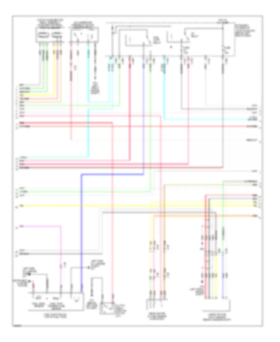
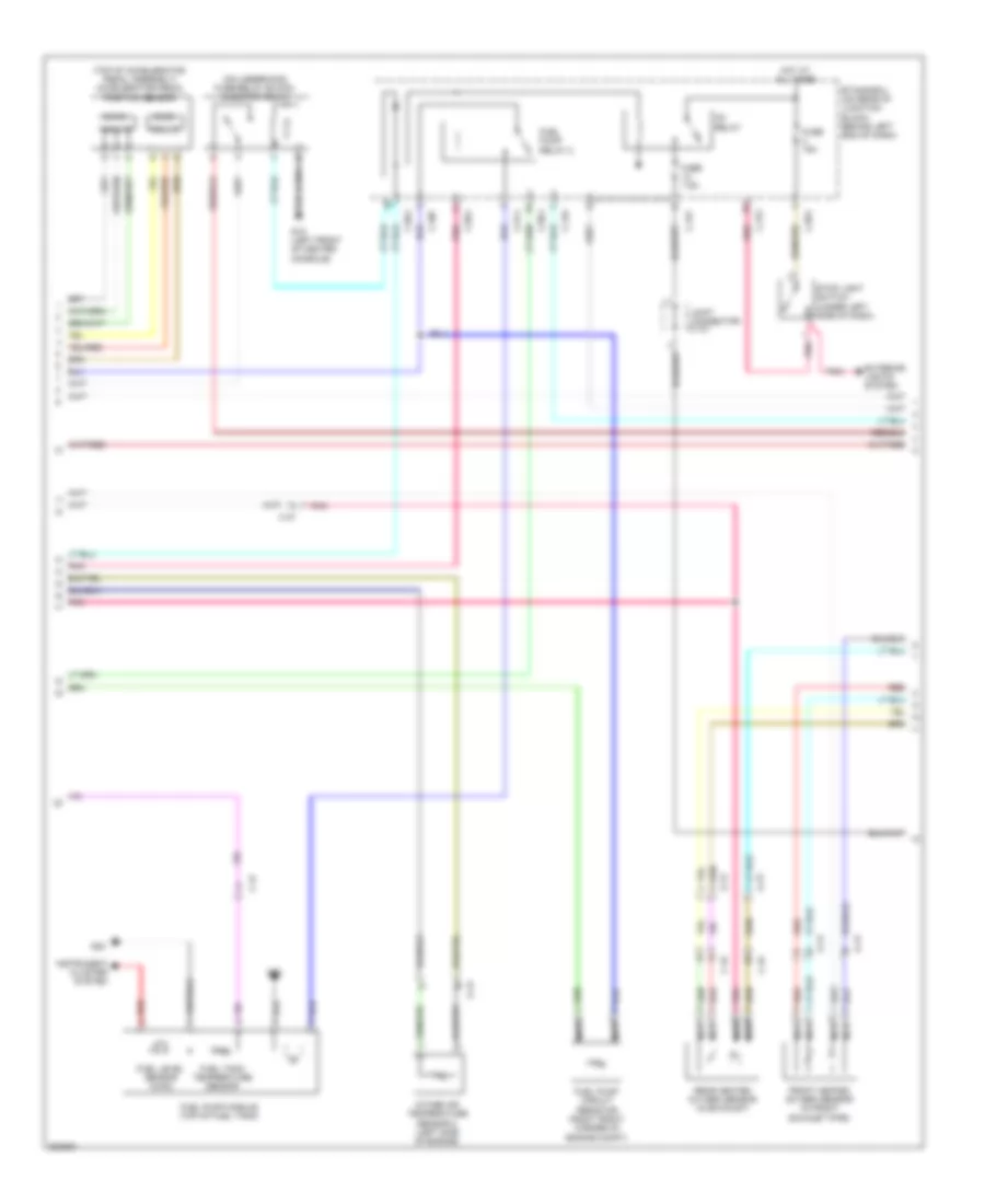
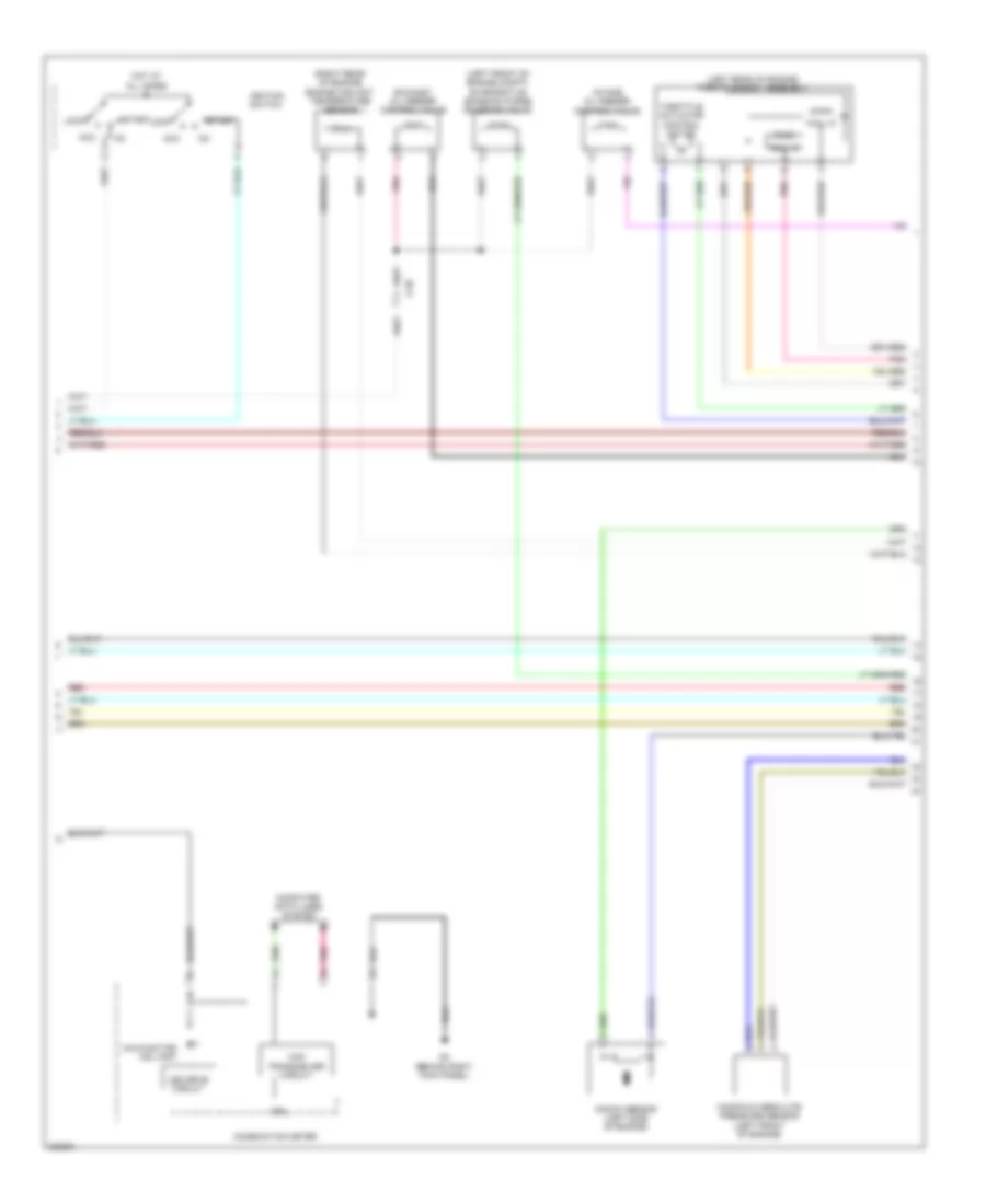
2.0L, Engine Performance Wiring Diagram (2 of 4) for Mitsubishi Lancer GT 2012
List of elements for 2.0L, Engine Performance Wiring Diagram (2 of 4) for Mitsubishi Lancer GT 2012:
- (left side of luggage compt) g11
- (main)
- (on underhood fuse/relay block) injector relay
- (sub)
- (top of accelerator pedal assembly) accelerator pedal position sensor
- A-09
- A-10
- C-304
- C-307
- C-312
- C-314
- C-315
- C-317
- C-39
- C-56
- Clutch pedal position switch (m/t)
- Etacs-ecu (on rear of junction block, behind left end of dash)
- Fuel level sensor
- Fuel pump module (top of fuel tank)
- Fuel pump relay
- Fuel tank temperature sensor
- Fuse 15a
- Fuse 7.5a
- G13 (behind left side of dash)
- G18 (left front engine compt)
- G20
- Hall ic
- Hot at all times
- Ig1 relay
- Instrument cluster system
- Linear air fuel ratio sensor (rear of engine compt)
- Pnk
- Rear heated oxygen sensor (in exhaust)
- Red
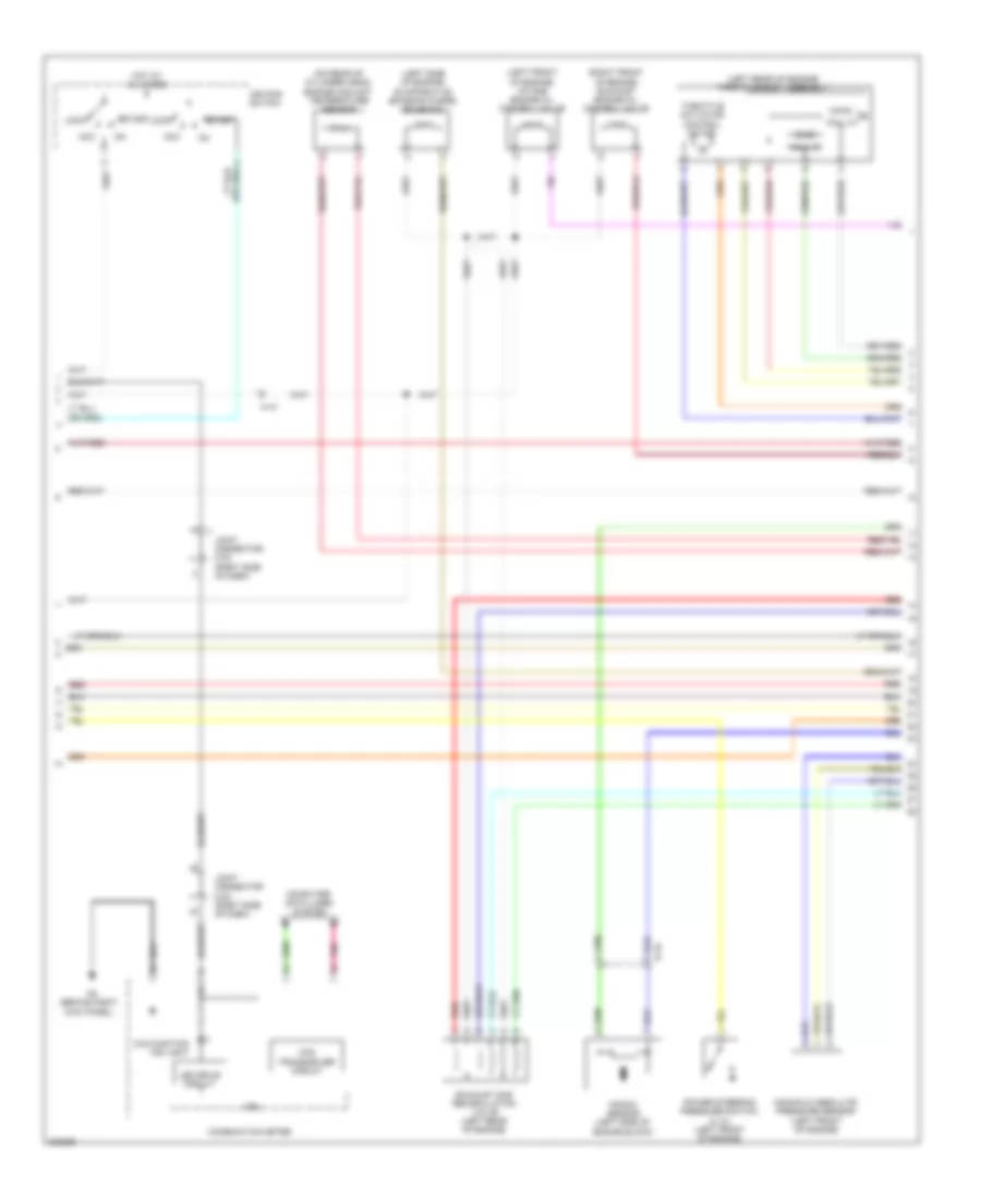
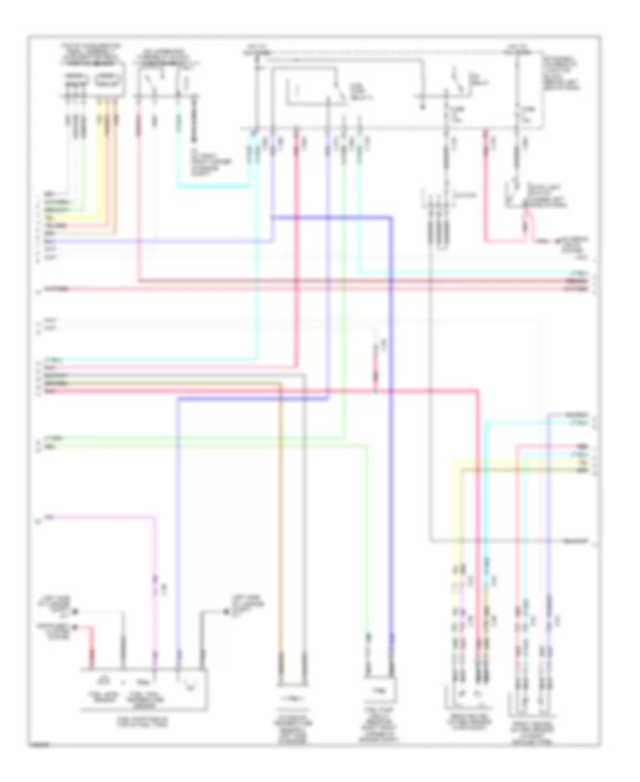
2.0L, Engine Performance Wiring Diagram (3 of 4) for Mitsubishi Lancer GT 2012
List of elements for 2.0L, Engine Performance Wiring Diagram (3 of 4) for Mitsubishi Lancer GT 2012:
- (behind right kick panel)
- (left front of engine) intake engine oil control valve
- (left rear of engine) throttle body assembly
- (left side of engine) evaporative emission purge solenoid
- (main)
- (on rear of cylinder head) engine coolant temperature sensor
- (right front of engine) exhaust engine oil control valve
- (sub)
- A-10
- Acc
- B-16
- Can transceiver circuit
- Combination meter
- Computer data lines system
- Cpu
- Exhaust gas recirculation valve (left rear of engine)
- Hall ic
- Hot at all times
- Ignition switch
- Joint connector c-03 (right side of dash)
- Knock sensor (left side of engine block)
- Led drive circuit
- Lock
- Malfunction ind light
- Manifold absolute pressure sensor (left front of engine)
- Pnk
- Power steering pressure switch (2.4l) (left front of engine)
- Red
- Start
- Throttle actuator control motor
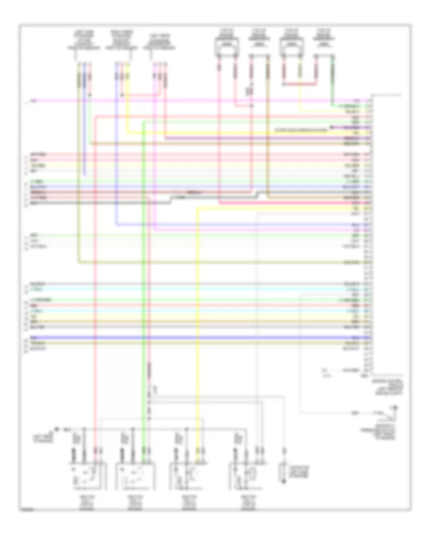
2.0L, Engine Performance Wiring Diagram (4 of 4) for Mitsubishi Lancer GT 2012
List of elements for 2.0L, Engine Performance Wiring Diagram (4 of 4) for Mitsubishi Lancer GT 2012:
- (left rear of engine) intake camshaft position sensor
- (on right rear of engine) crankshaft position sensor
- (right rear of engine) exhaust camshaft position sensor
- (top of engine)
- (top of engine) injector 1
- (top of engine) injector 2
- (top of engine) injector 3
- (top of engine) injector 4
- A-10
- B-108
- B-16
- Engine control module (left rear of engine compt)
- Engine oil pressure switch (left front of engine)
- G2 (right rear of engine)
- Ignition coil 1
- Ignition coil 2
- Ignition coil 3
- Ignition coil 4
- Nca
- Plug spark
- Pnk
- Red
- Spark plug
- Starting/charging system
2.0L TURBO
2.0L Turbo, Engine Performance Wiring Diagram, Evolution (1 of 4) for Mitsubishi Lancer GT 2012
List of elements for 2.0L Turbo, Engine Performance Wiring Diagram, Evolution (1 of 4) for Mitsubishi Lancer GT 2012:
- (not used)
- (on underhood fuse/relay block) fuel pump relay 1
- (on underhood fuse/relay block) throttle actuator control motor relay
- A-13
- Air conditioning system
- B-09
- B-10
- C-47
- Computer data lines system
- Cruise control system
- D-17
- Engine compartment fuse/relay box (left side of engine compt)
- Engine control module (left rear of engine compt)
- Evaporative emission ventilation solenoid (under rear of vehicle)
- Fuel tank differential pressure sensor (on top of fuel tank)
- Fuse 10a
- Fuse 15a
- Fuse 20a
- Fuse 7.5a
- Fusible link 36 120a
- Fusible link box (next to battery)
- G15 (left front of center console)
- G16 (rear of engine compt)
- G5 (right of accelerator pedal)
- Hot at all times
- Mass airflow sensor (right rear of engine)
- Mfi relay
- Nca
- Pnk
- Power steering pressure switch (left front of engine)
- Red
- Starting/ charging system
- Starting/charging system
- Turbocharger wastegate solenoid 1 (rear of engine)
- Turbocharger wastegate solenoid 2 (rear of engine)
2.0L Turbo, Engine Performance Wiring Diagram, Evolution (2 of 4) for Mitsubishi Lancer GT 2012
List of elements for 2.0L Turbo, Engine Performance Wiring Diagram, Evolution (2 of 4) for Mitsubishi Lancer GT 2012:
- (main)
- (on underhood fuse/relay block) injector relay
- (sub)
- (top of accelerator pedal assembly) accelerator pedal position sensor
- A-13
- C-304
- C-307
- C-312
- C-314
- C-315
- C-317
- C-45
- C-47
- Etacs-ecu (on rear of junction block, behind left end of dash)
- Exterior lights system
- Front heated oxygen sensor (in front exhaust pipe)
- Fuel level sensor (main)
- Fuel pump circuit resistor (right front corner of engine compt)
- Fuel pump module (top of fuel tank)
- Fuel pump relay 2
- Fuel tank temperature sensor
- Fuse 15a
- Fuse 7.5a
- G15 (left front of center console)
- G22
- Hall ic
- Hot at all times
- Ig1 relay
- Instrument cluster system
- Intake air temperature sensor 2 (left side of engine)
- Joint connector c-101
- Nca
- Pnk
- Rear heated oxygen sensor (in exhaust)
- Red
- Stop light switch (under left side of dash)
2.0L Turbo, Engine Performance Wiring Diagram, Evolution (3 of 4) for Mitsubishi Lancer GT 2012
List of elements for 2.0L Turbo, Engine Performance Wiring Diagram, Evolution (3 of 4) for Mitsubishi Lancer GT 2012:
- (left front of engine compt) evaporative emission purge solenoid valve
- (left rear of engine) throttle body assembly
- (main)
- (right rear of engine) engine coolant temperature sensor
- (sub)
- A-39
- Acc
- Can transceiver circuit
- Combination meter
- Computer data lines system
- Cpu
- Exhaust oil feeder control valve
- G4 (behind right kick panel)
- Hall ic
- Hot at all times
- Ignition switch
- Intake oil feeder control valve
- Knock sensor (left side of engine)
- Led drive circuit
- Lock
- Malfunction ind light
- Manifold absolute pressure sensor (left front of engine)
- Pnk
- Red
- Start
- Throttle actuator control motor
2.0L Turbo, Engine Performance Wiring Diagram, Evolution (4 of 4) for Mitsubishi Lancer GT 2012
List of elements for 2.0L Turbo, Engine Performance Wiring Diagram, Evolution (4 of 4) for Mitsubishi Lancer GT 2012:
- (left rear
- (left side of engine) intake camshaft position sensor
- (right rear of engine) exhaust camshaft position sensor
- (top of engine) injector 1
- (top of engine) injector 2
- (top of engine) injector 3
- (top of engine) injector 4
- A-13
- A-39
- B-09
- Capacitor (left side of engine)
- Engine control module (left rear of engine compt)
- Engine oil pressure switch (left front of engine)
- G3 (left rear of engine)
- Ignition coil 1 (top of engine)
- Ignition coil 2 (top of engine)
- Ignition coil 3 (top of engine)
- Ignition coil 4 (top of engine)
- Nca
- Of engine) crankshaft position sensor
- Plug spark
- Pnk
- Red
- Spark plug
- Starting/charging system
2.0L Turbo, Engine Performance Wiring Diagram, Except Evolution (1 of 4) for Mitsubishi Lancer GT 2012
List of elements for 2.0L Turbo, Engine Performance Wiring Diagram, Except Evolution (1 of 4) for Mitsubishi Lancer GT 2012:
- (on underhood fuse/relay block) fuel pump relay 1
- (on underhood fuse/relay block) throttle actuator control motor relay
- A-54
- Air conditioning system
- B-108
- B-109
- C-39
- Computer data lines system
- Cruise control system
- D-14
- Engine compartment fuse/relay box (left side of engine compt)
- Engine control module (left rear of engine compt)
- Evaporative emission ventilation solenoid (under rear of vehicle)
- Fuel tank differential pressure sensor (on top of fuel tank)
- Fuse 10a
- Fuse 15a
- Fuse 20a
- Fuse 7.5a
- Fusible link 36 120a
- Fusible link box (next to battery)
- G16 (rear of engine compt)
- G17 (left front of engine compt)
- G18 (left front of engine compt)
- Hot at all times
- Mass airflow sensor (right rear of engine)
- Mfi relay
- Nca
- Pnk
- Power steering pressure switch (left front of engine)
- Red
- Starting/ charging system
- Starting/charging system
- Turbocharger wastegate solenoid (rear of engine)
2.0L Turbo, Engine Performance Wiring Diagram, Except Evolution (2 of 4) for Mitsubishi Lancer GT 2012
List of elements for 2.0L Turbo, Engine Performance Wiring Diagram, Except Evolution (2 of 4) for Mitsubishi Lancer GT 2012:
- (left side of luggage compt) g11
- (main)
- (on underhood fuse/relay block) injector relay
- (sub)
- (top of accelerator pedal assembly) accelerator pedal position sensor
- A-54
- C-304
- C-307
- C-312
- C-314
- C-315
- C-317
- C-39
- C-56
- Etacs-ecu (on rear of junction block, behind left end of dash)
- Exterior lights system
- Front heated oxygen sensor (in front exhaust pipe)
- Fuel level sensor
- Fuel pump circuit resistor (right front corner of engine compt)
- Fuel pump module (top of fuel tank)
- Fuel pump relay 2
- Fuel tank temperature sensor
- Fuse 15a
- Fuse 7.5a
- G1 (at right front corner of engine compt)
- Hall ic
- Hot at all times
- Ig1 relay
- Instrument cluster system
- Intake air temperature sensor 2 (left side of engine)
- J/c c103
- Nca
- Pnk
- Rear heated oxygen sensor (in exhaust)
- Red
- Stop light switch (under left side of dash)
2.0L Turbo, Engine Performance Wiring Diagram, Except Evolution (3 of 4) for Mitsubishi Lancer GT 2012
List of elements for 2.0L Turbo, Engine Performance Wiring Diagram, Except Evolution (3 of 4) for Mitsubishi Lancer GT 2012:
- (left front of engine compt) evaporative emission purge solenoid valve
- (left rear of engine) throttle body assembly
- (main)
- (right rear of engine) engine coolant temperature sensor
- (sub)
- A-60
- Acc
- Can transceiver circuit
- Combination meter
- Computer data lines system
- Cpu
- Exhaust oil feeder control valve
- G4 (behind right kick panel)
- Hall ic
- Hot at all times
- Ignition switch
- Intake oil feeder control valve
- Knock sensor (left side of engine)
- Lcd (malfunction indicator light (service engine soon))
- Led drive circuit
- Lock
- Malfunction ind light
- Manifold absolute pressure sensor (left front of engine)
- Pnk
- Red
- Start
- Throttle actuator control motor
2.0L Turbo, Engine Performance Wiring Diagram, Except Evolution (4 of 4) for Mitsubishi Lancer GT 2012
List of elements for 2.0L Turbo, Engine Performance Wiring Diagram, Except Evolution (4 of 4) for Mitsubishi Lancer GT 2012:
- (left rear of engine) crankshaft position sensor
- (left side of engine) intake camshaft position sensor
- (right rear of engine) exhaust camshaft position sensor
- (top of engine) injector 1
- (top of engine) injector 2
- (top of engine) injector 3
- (top of engine) injector 4
- A-60
- B-108
- B-16
- Capacitor
- Engine control module (left rear of engine compt)
- Engine oil pressure switch (left front of engine)
- G2 (rear of engine)
- Ignition coil 1 (top of engine)
- Ignition coil 2 (top of engine)
- Ignition coil 3 (top of engine)
- Ignition coil 4 (top of engine)
- Nca
- Plug spark
- Pnk
- Red
- Spark plug
- Starting/charging system
2.4L
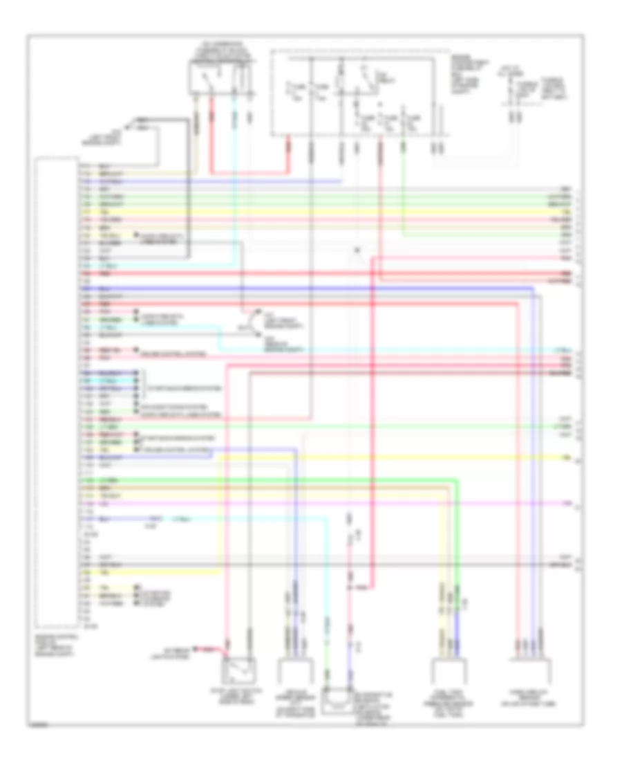
2.4L, Engine Performance Wiring Diagram (1 of 4) for Mitsubishi Lancer GT 2012
List of elements for 2.4L, Engine Performance Wiring Diagram (1 of 4) for Mitsubishi Lancer GT 2012:
- (on underhood fuse/relay block) throttle actuator control motor relay
- A-10
- Air conditioning system
- B-108
- B-109
- C-39
- Computer data lines system
- Cruise control system
- D-14
- Engine compartment fuse/relay box (left side of engine compt)
- Engine control module (left rear of engine compt)
- Evaporative emission ventilation solenoid (under rear of vehicle)
- Exterior lights system
- Fuel tank differential pressure sensor (on top of fuel tank)
- Fuse 10a
- Fuse 15a
- Fuse 20a
- Fuse 7.5a
- Fusible link 36 120a
- Fusible link box (next to battery)
- G16 (rear of engine compt)
- G17 (left front engine compt)
- G18 (left front engine compt)
- Hot at all times
- Mass airflow sensor (on air intake tube)
- Mfi relay
- Pnk
- Red
- Starting/ charging system
- Starting/charging system
- Stop light switch (under left side of dash)
- Vehicle speed sensor (m/t) (on right side of transaxle)
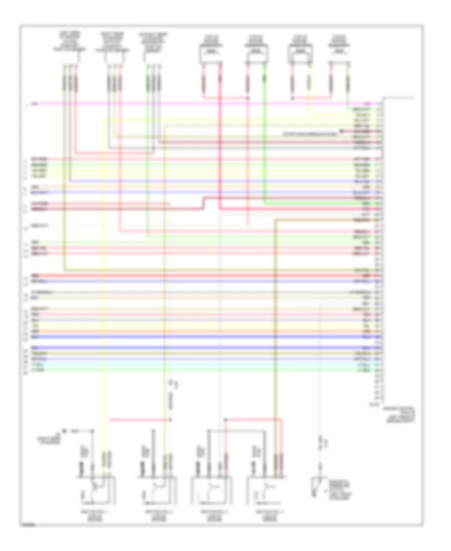
2.4L, Engine Performance Wiring Diagram (2 of 4) for Mitsubishi Lancer GT 2012
List of elements for 2.4L, Engine Performance Wiring Diagram (2 of 4) for Mitsubishi Lancer GT 2012:
- (left side of luggage compt) g11
- (main)
- (on underhood fuse/relay block) injector relay
- (sub)
- (top of accelerator pedal assembly) accelerator pedal position sensor
- A-09
- A-10
- C-304
- C-307
- C-312
- C-314
- C-315
- C-317
- C-39
- C-56
- Clutch pedal position switch (m/t)
- Etacs-ecu (on rear of junction block, behind left end of dash)
- Fuel level sensor
- Fuel pump module (top of fuel tank)
- Fuel pump relay
- Fuel tank temperature sensor
- Fuse 15a
- Fuse 7.5a
- G13 (behind left side of dash)
- G18 (left front engine compt)
- G20
- Hall ic
- Hot at all times
- Ig1 relay
- Instrument cluster system
- Linear air fuel ratio sensor (rear of engine compt)
- Pnk
- Rear heated oxygen sensor (in exhaust)
- Red
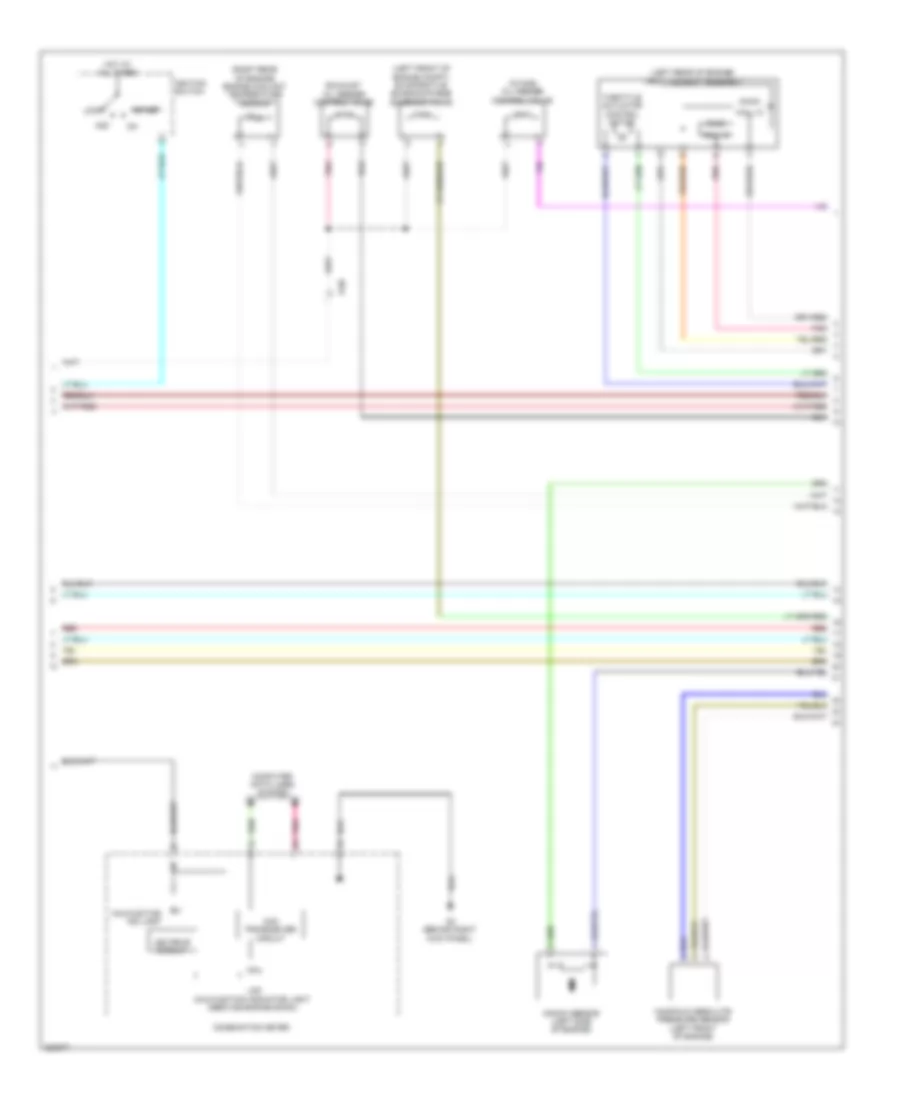
2.4L, Engine Performance Wiring Diagram (3 of 4) for Mitsubishi Lancer GT 2012
List of elements for 2.4L, Engine Performance Wiring Diagram (3 of 4) for Mitsubishi Lancer GT 2012:
- (behind right kick panel)
- (left front of engine) intake engine oil control valve
- (left rear of engine) throttle body assembly
- (left side of engine) evaporative emission purge solenoid
- (main)
- (on rear of cylinder head) engine coolant temperature sensor
- (right front of engine) exhaust engine oil control valve
- (sub)
- A-10
- Acc
- B-16
- Can transceiver circuit
- Combination meter
- Computer data lines system
- Cpu
- Exhaust gas recirculation valve (left rear of engine)
- Hall ic
- Hot at all times
- Ignition switch
- Joint connector c-03 (right side of dash)
- Knock sensor (left side of engine block)
- Led drive circuit
- Lock
- Malfunction ind light
- Manifold absolute pressure sensor (left front of engine)
- Pnk
- Power steering pressure switch (2.4l) (left front of engine)
- Red
- Start
- Throttle actuator control motor
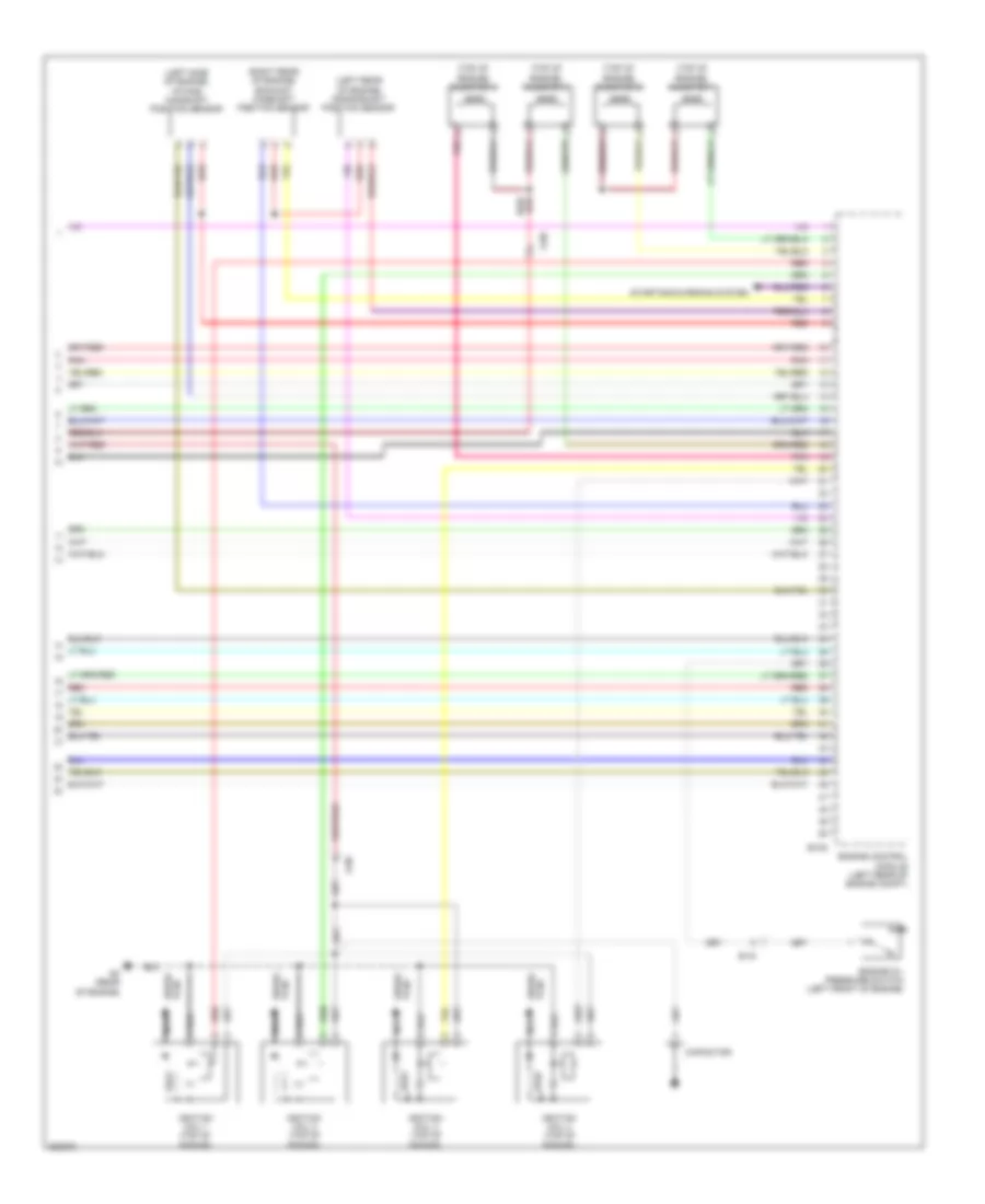
2.4L, Engine Performance Wiring Diagram (4 of 4) for Mitsubishi Lancer GT 2012
List of elements for 2.4L, Engine Performance Wiring Diagram (4 of 4) for Mitsubishi Lancer GT 2012:
- (left rear of engine) intake camshaft position sensor
- (on right rear of engine) crankshaft position sensor
- (right rear of engine) exhaust camshaft position sensor
- (top of engine)
- (top of engine) injector 1
- (top of engine) injector 2
- (top of engine) injector 3
- (top of engine) injector 4
- A-10
- B-108
- B-16
- Engine control module (left rear of engine compt)
- Engine oil pressure switch (left front of engine)
- G2 (right rear of engine)
- Ignition coil 1
- Ignition coil 2
- Ignition coil 3
- Ignition coil 4
- Nca
- Plug spark
- Pnk
- Red
- Spark plug
- Starting/charging system