ENGINE PERFORMANCE
2.0L
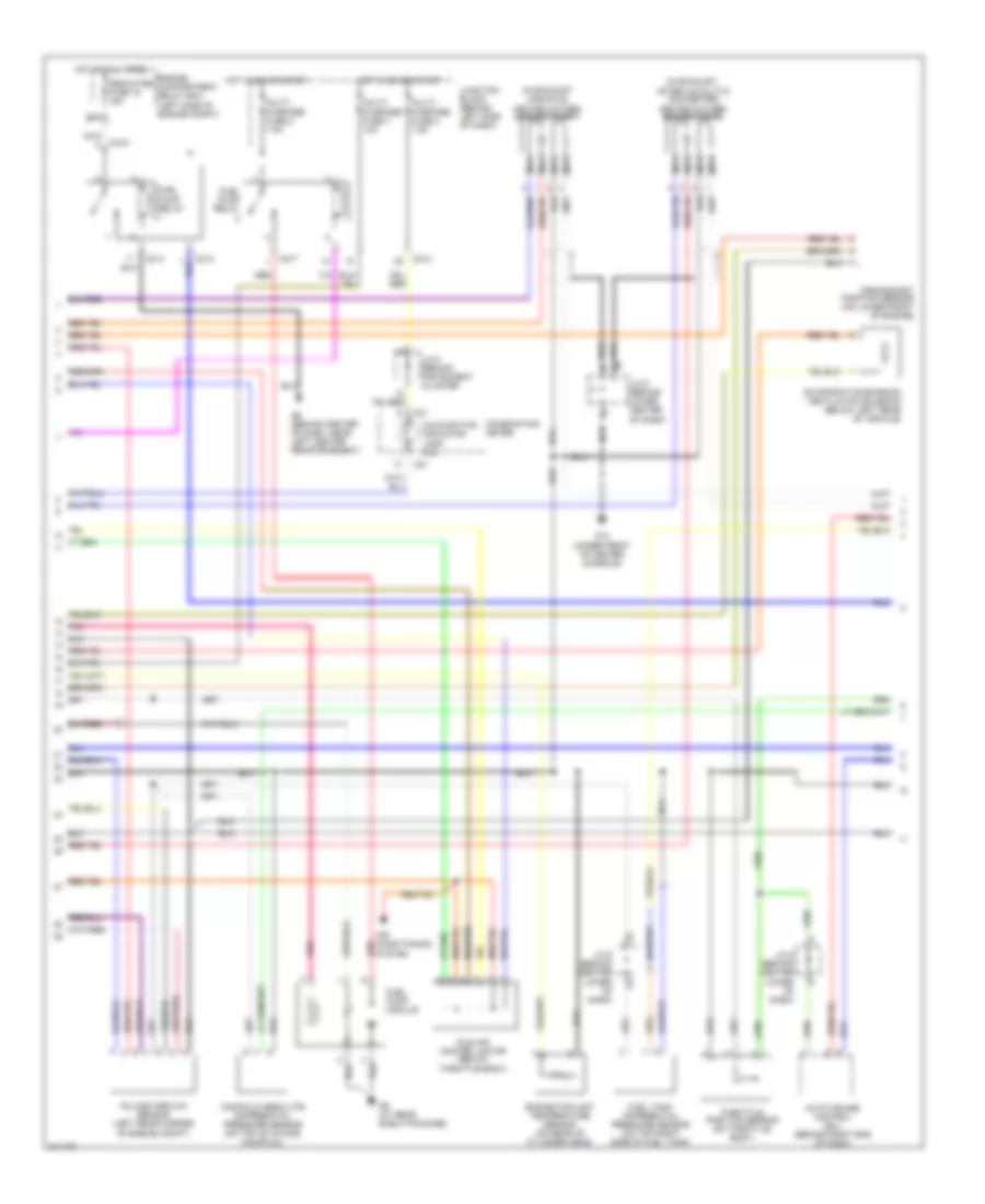
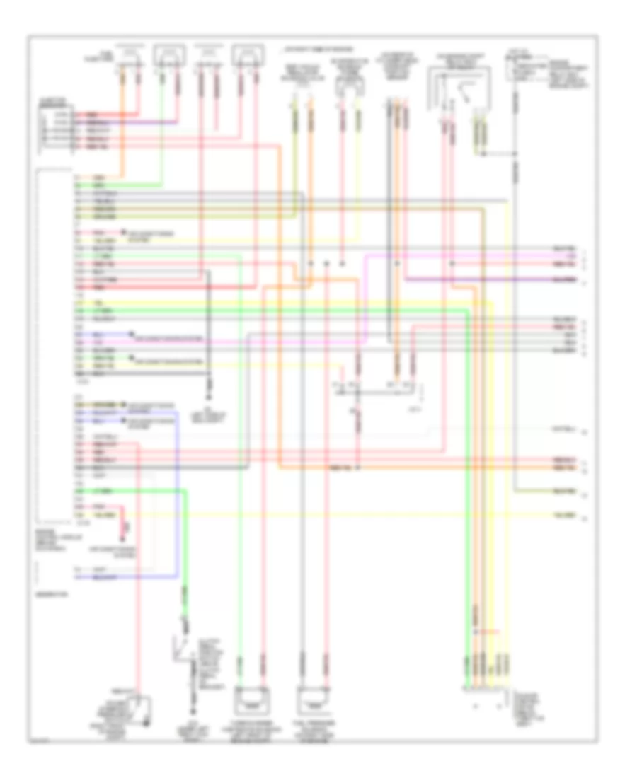
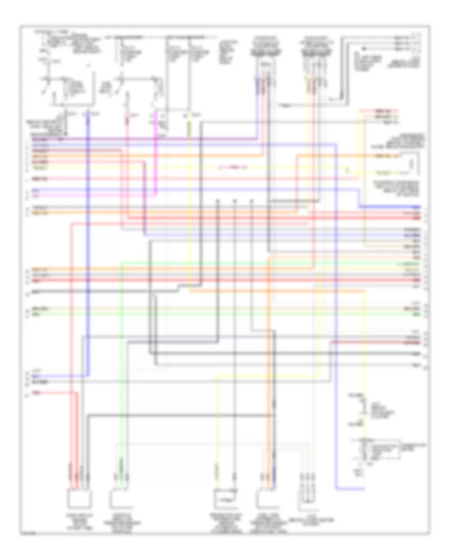
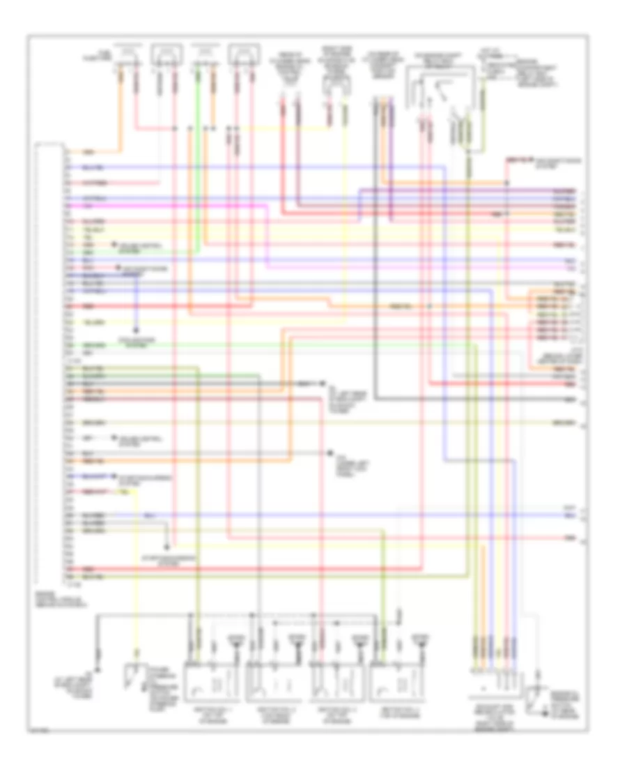
2.0L, Engine Performance Wiring Diagram, with A/T (1 of 3) for Mitsubishi Lancer O-Z Rally 2005

List of elements for 2.0L, Engine Performance Wiring Diagram, with A/T (1 of 3) for Mitsubishi Lancer O-Z Rally 2005:
- (behind lower center of dash) j/c 6
- (on engine compt relay box) mfi relay
- (on rear of cylinder head) camshaft position sensor
- (right side of engine)
- Air conditioning system
- C118
- C120
- Dedicated fuse 8 20a
- Egr solenoid valve
- Engine compartment relay box (left side of engine compt)
- Engine speed detection connector (in engine compt relay box)
- Evaporative emission purge solenoid
- Fuel injectors
- G11 (left side of cylinder head, under throttle cable)
- G14 (under front of center console)
- G4 (at left rear of engine compt, on shock tower)
- Generator
- Hot at all times
- Ignition coil 1 (at top of valve cover)
- Ignition coil 2
- Instrument cluster system
- J/c 6 (behind lower center of dash)
- Nca
- Pnk
- Power steering oil pressure switch (right front of engine compt)
- Powertrain control module (behind glove box)
- Red
- Spark plugs
- Starting/ charging system
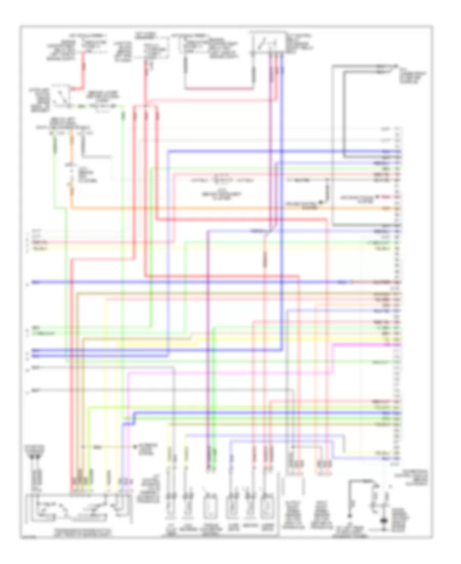
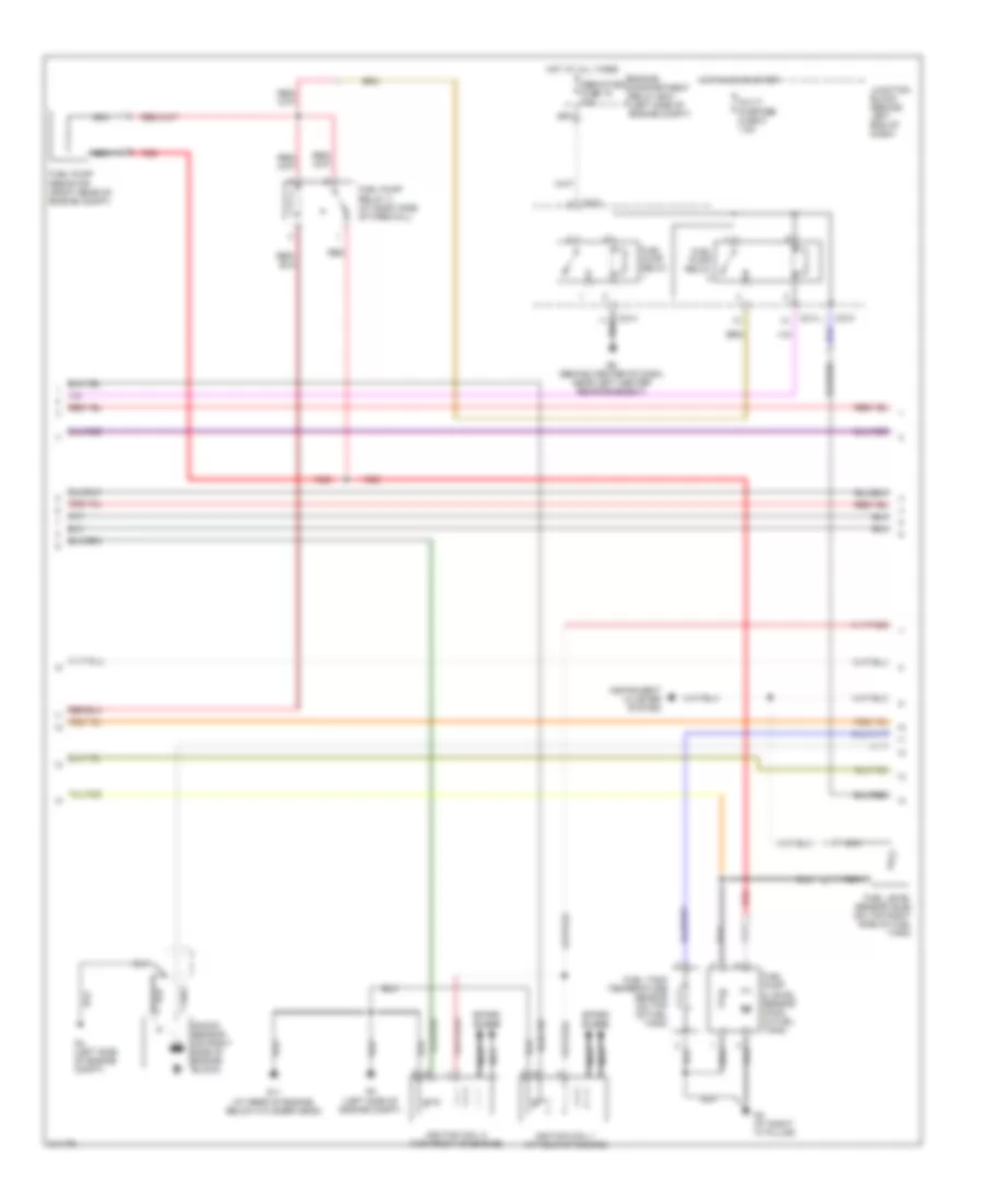
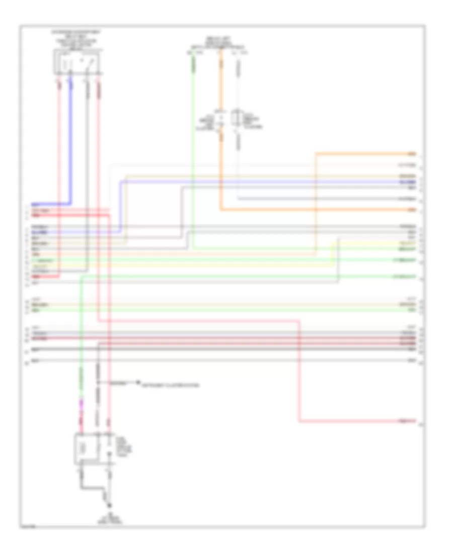
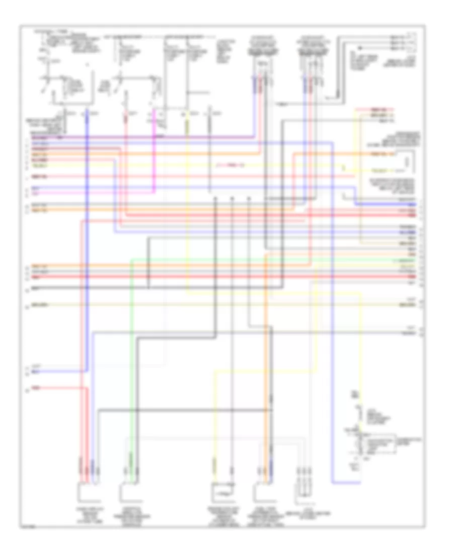
2.0L, Engine Performance Wiring Diagram, with A/T (2 of 3) for Mitsubishi Lancer O-Z Rally 2005
List of elements for 2.0L, Engine Performance Wiring Diagram, with A/T (2 of 3) for Mitsubishi Lancer O-Z Rally 2005:
- (in exhaust manifold) heated oxygen sensor (front)
- (in exhaust, after catalytic converter) heated oxygen sensor (rear)
- Air conditioning
- Auto cruise control ecu (behind right end of dash)
- C01
- C210
- C214
- C217
- Combination meter
- Crankshaft position sensor (on lower front of engine)
- Dedicated fuse 15 15a
- Engine compartment relay box (left side of engine compt)
- Engine coolant temperature sensor (on rear of cylinder head)
- Evaporative emission ventilation solenoid (below left rear of vehicle)
- Fuel pump module
- Fuel pump relay
- Fuel tank differential pressure sensor (on top right side of fuel tank)
- G14 (under front of center console)
- G6 (behind center of dash, near left center reinforcement)
- G9 (at rear shelf package)
- Hot at all times
- Hot in on or start
- Idle air control motor (below throttle body)
- J/c 5 (behind instrument cluster
- J/c 6 (behind center lower of dash)
- J/c 6 (behind lower center of dash)
- Junction block (behind left side of dash)
- Malfunction indicator lamp (mil)
- Manifold absolute differential pressure sensor (on top of intake manifold)
- Multi- purpose fuse 1 10a
- Multi- purpose fuse 2 7.5a
- Multi- purpose fuse 8 7.5a
- Nca
- Pnk
- Red
- System red
- Throttle position sensor (on throttle body)
- Volume airflow sensor (left rear corner of engine compt)
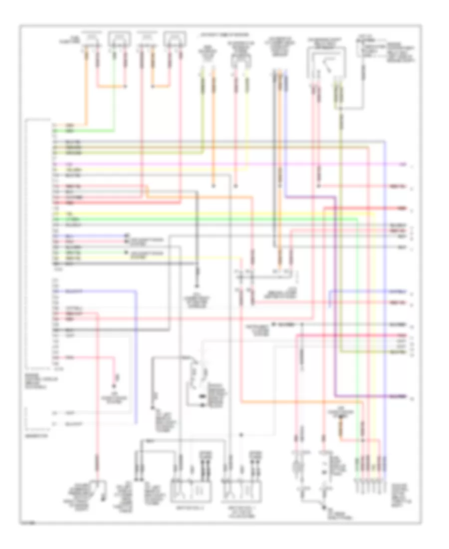
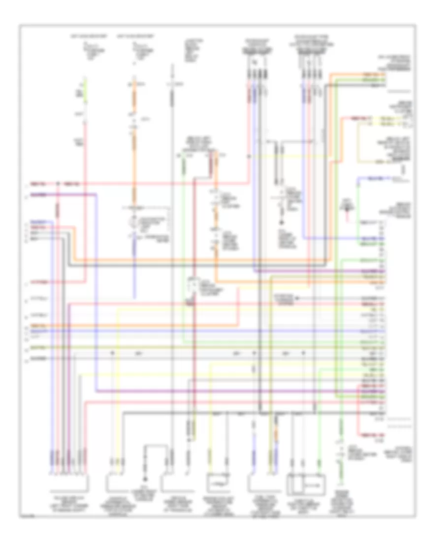
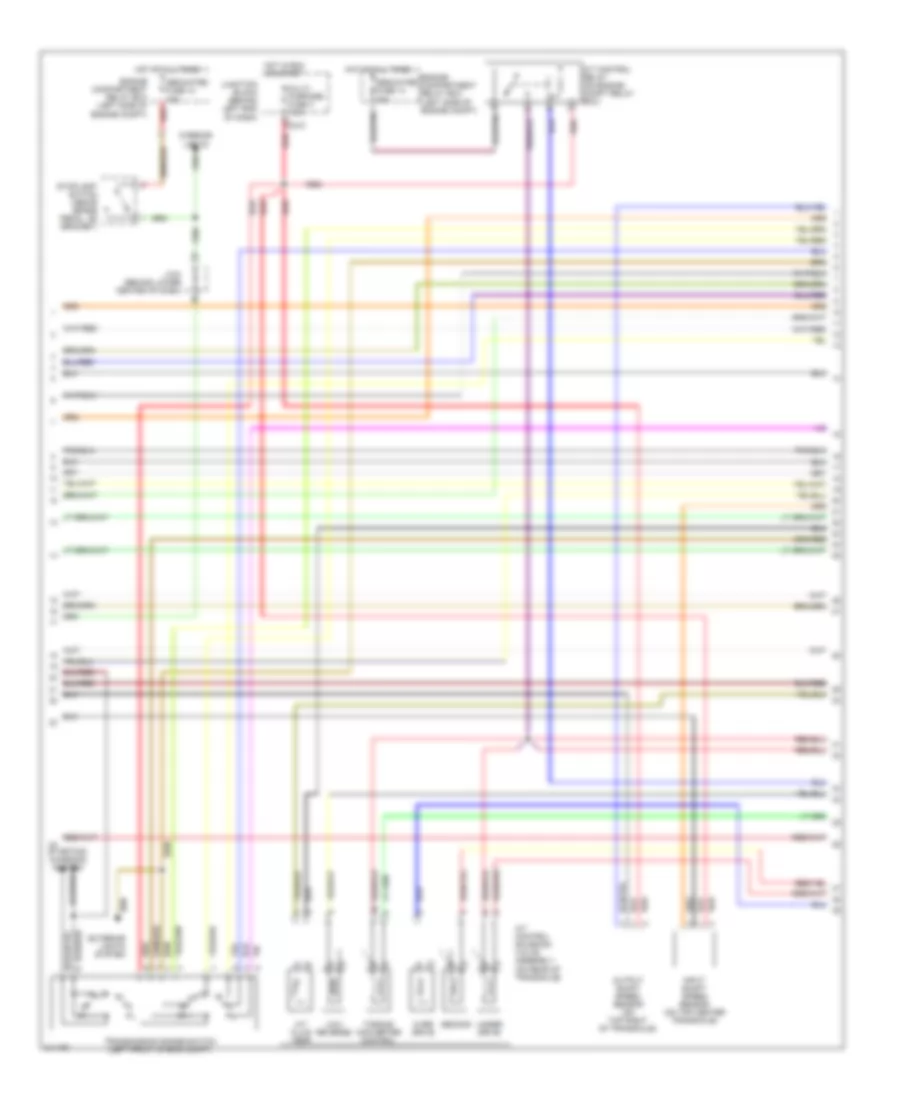
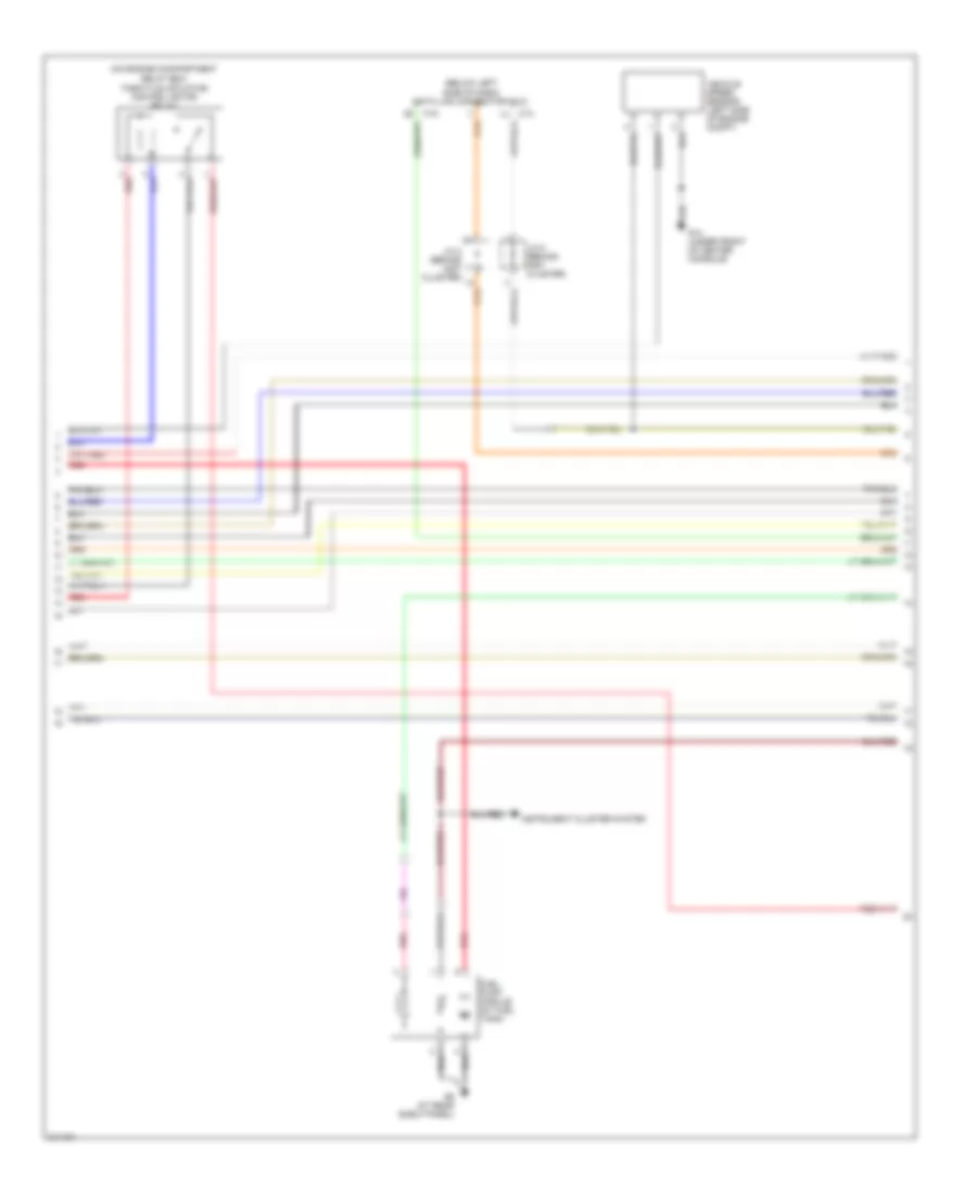
2.0L, Engine Performance Wiring Diagram, with A/T (3 of 3) for Mitsubishi Lancer O-Z Rally 2005
List of elements for 2.0L, Engine Performance Wiring Diagram, with A/T (3 of 3) for Mitsubishi Lancer O-Z Rally 2005:
- (behind lower center of dash) j/c 6
- (below left side of dash) data link connector (dlc)
- A/t control relay (on engine compt relay box)
- A/t control solenoid valve assembly (on rear of transaxle)
- A/t fluid temp
- Air conditioning system
- C114
- C116
- C14
- C15
- C210
- Cruise control system
- Dedicated fuse 10 15a
- Dedicated fuse 14 20a
- Engine compartment relay box (left side of engine compt)
- Exterior lights system
- G14 (under front of center console)
- G4 (at left rear of eng compt, on shock tower)
- Hot at all times
- Hot in run or start
- Input shaft speed sensor (on top center of transaxle)
- J/c 2 (behind inst cluster)
- J/c 5 (behind instrument cluster)
- Junction block (behind left end of dash)
- Knock sensor (on right side of engine block)
- Low/ reverse
- Multi- purpose fuse 3 7.5a
- Output shaft speed sensor (on top right of transaxle)
- Over drive
- Pnk
- Powertrain control module (behind glove box)
- Red
- Second
- Starting/ charging system
- Stoplight switch (above brake pedal, on bracket)
- Torque converter control
- Transmission range switch (left front of engine compt)
- Under drive
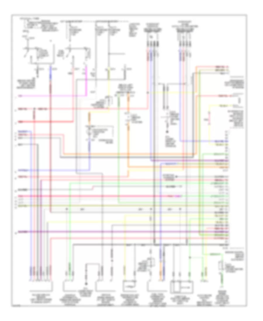
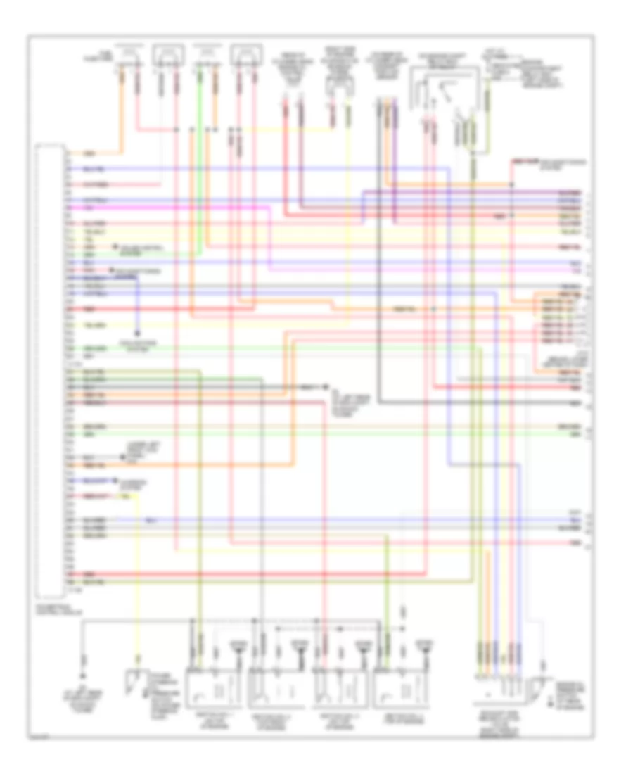
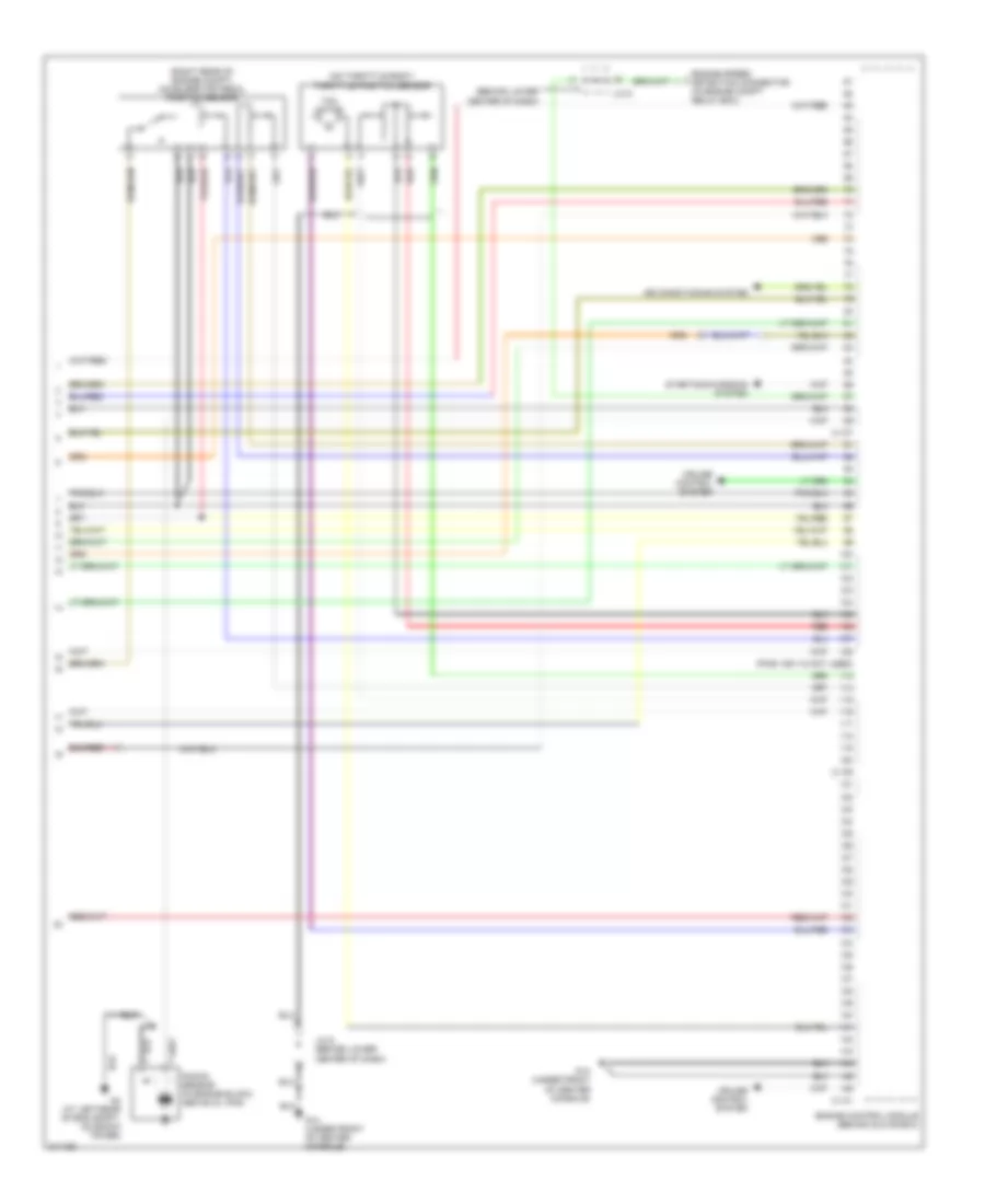
2.0L, Engine Performance Wiring Diagram, with M/T (1 of 2) for Mitsubishi Lancer O-Z Rally 2005
List of elements for 2.0L, Engine Performance Wiring Diagram, with M/T (1 of 2) for Mitsubishi Lancer O-Z Rally 2005:
- (on engine compt relay box) mfi relay
- (on rear of cylinder head) camshaft position sensor
- (on right side of engine)
- Air conditioning system
- Air conditioning system
- C119
- C121
- D10
- D12
- Dedicated fuse 8 20a
- Egr solenoid valve
- Engine compartment relay box (left side of engine compt)
- Engine control module (behind glove box)
- Evaporative emission purge solenoid
- Fuel injectors
- Fuel pump module (at fuel tank)
- G11 (on left side of cylinder head, under throttle cable)
- G14 (under front of center console)
- G4 (at left rear of eng compt, on shock tower)
- G9 (at rear shelf panel)
- Generator
- Hot at all times
- Idle air control motor (below throttle body)
- Ignition coil 1 (at top of valve cover)
- Ignition coil 2
- Instrument cluster system
- J/c 6 (behind lower center of dash)
- Knock sensor (on right side of engine block)
- Nca
- Pnk
- Power steering pressure switch (right front of engine compt)
- Red
- Spark plugs
2.0L, Engine Performance Wiring Diagram, with M/T (2 of 2) for Mitsubishi Lancer O-Z Rally 2005
List of elements for 2.0L, Engine Performance Wiring Diagram, with M/T (2 of 2) for Mitsubishi Lancer O-Z Rally 2005:
- (below left side of dash) data link connector (dlc)
- (in exhaust manifold) heated oxygen sensor (front)
- (in exhaust, after catalytic converter) heated oxygen sensor (rear)
- Auto cruise control ecu (behind right end of dash)
- C01
- C115
- C117
- C14
- C15
- C210
- C214
- C217
- Combination meter
- Crankshaft position sensor (on lower front of engine)
- Dedicated fuse 15 15a
- Engine compartment relay box (left side of engine compt)
- Engine control module (behind glove box)
- Engine coolant temperature sensor (on rear of cylinder head)
- Engine speed detection connector (in engine compt relay box)
- Evaporative emission ventilation solenoid (below left rear of vehicle)
- Fuel pump relay
- Fuel tank differential pressure sensor (top right side of fuel tank)
- G14 (under front of center console)
- G6 (behind center of dash, near left center reinforcement)
- Hot at all times
- Hot in on or start
- J/c 2 (behind inst cluster)
- J/c 5 (behind instrument cluster)
- J/c 6 (behind lower center of dash)
- J/c 6 (behind lower center of dash)
- Junction block (behind left end of dash)
- Malfunction indicator lamp (mil)
- Manifold differential pressure sensor (top of intake manifold)
- Multi- purpose fuse 1 10a
- Multi- purpose fuse 2 7.5a
- Multi- purpose fuse 8 7.5a
- Nca
- Pnk
- Red
- Starting/ charging system
- Throttle position sensor (on throttle body)
- Vehicle speed sensor (at left side of engine compartment)
- Volume airflow sensor (left rear corner of engine compt)
2.0L TURBO
2.0L Turbo, Engine Performance Wiring Diagram (1 of 3) for Mitsubishi Lancer O-Z Rally 2005
List of elements for 2.0L Turbo, Engine Performance Wiring Diagram (1 of 3) for Mitsubishi Lancer O-Z Rally 2005:
- (on engine compt relay box) mfi relay
- (on rear of cylinder head) camshaft position sensor
- (on right side of engine)
- Air conditioning system
- C119
- C121
- Clutch pedal position switch (above nca
- Clutch pedal, on bracket)
- Dedicated fuse 8 20a
- Egr vacuum regulator solenoid valve
- Engine compartment relay box (left side of engine compt)
- Engine control module (behind glove box)
- Evaporative emission purge solenoid
- Fuel injectors
- Fuel pressure solenoid (on right side of engine)
- G15 (under left front kick panel)
- G4 (left side of eng compt)
- Generator
- Hot at all times
- Idle air control motor (below throttle body)
- Injector resistor
- J/c 4
- Nca
- Pnk
- Power steering pressure switch (right front of engine compt)
- Red
- Turbocharger wastegate solenoid (left front of engine compt)
2.0L Turbo, Engine Performance Wiring Diagram (2 of 3) for Mitsubishi Lancer O-Z Rally 2005
List of elements for 2.0L Turbo, Engine Performance Wiring Diagram (2 of 3) for Mitsubishi Lancer O-Z Rally 2005:
- C210
- C214
- Dedicated fuse 15 20a
- Engine compartment relay box (left side of engine compt)
- Fuel level sensor (sub) (on top right side of fuel tank)
- Fuel pump & level sensor (main) (in fuel tank)
- Fuel pump relay
- Fuel pump relay 3 (at right side of firewall)
- Fuel pump resistor (right rear of engine compt)
- Fuel tank temperature sensor (on top of fuel tank)
- G11 (at rear of engine, below cylinder head)
- G2 (at right "a" pillar)
- G4 (left side of engine compt)
- G6 (behind center of dash, near left center reinforcement)
- Hot at all times
- Hot in on or start
- Ignition coil 1 (at rear of engine)
- Ignition coil 2 (top front of engine)
- Instrument cluster system
- Junction block (behind left end of dash)
- Knock sensor (on right side of engine block)
- Multi- purpose fuse 8 7.5a
- Nca
- Red
- Spark plugs
2.0L Turbo, Engine Performance Wiring Diagram (3 of 3) for Mitsubishi Lancer O-Z Rally 2005
List of elements for 2.0L Turbo, Engine Performance Wiring Diagram (3 of 3) for Mitsubishi Lancer O-Z Rally 2005:
- (behind glove box) engine control module
- (behind instrument cluster) j/c 5
- (below left rear of vehicle) evaporative emission ventilation solenoid
- (below left side of dash) data link connector (dlc)
- (on exhaust manifold) heated oxygen sensor (front)
- (on exhaust pipe, downstream of catalytic converter) heated oxygen sensor (rear)
- (on lower front of engine) crankshaft position sensor
- Anti theft system
- Awd-ecu (behind lower right side of dash)
- C01
- C115
- C117
- C138
- C14
- C15
- C210
- C214
- Combination meter
- Engine coolant temperature sensor (on rear of cylinder head)
- Engine speed detection connector (in engine compt relay box)
- Fuel tank differential pressure sensor (top right side of fuel tank)
- G14 (under front of center console)
- Hot in on or start
- J/c 2 (behind inst cluster)
- J/c 4
- J/c 5 (behind instrument cluster)
- J/c 6 (behind lower center of dash)
- J/c 6 (behind lower center of dash)
- Junction block (behind left end of dash)
- Malfunction indicator lamp (mil)
- Manifold differential pressure sensor (top of intake manifold)
- Multi- purpose fuse 1 10a
- Multi- purpose fuse 2 7.5a
- Nca
- Starting/ charging system
- Throttle position sensor (on throttle body)
- Vehicle speed sensor (right side of transaxle)
- Volume airflow sensor (left front corner of engine compt)
2.4L
2.4L, Engine Performance Wiring Diagram, with A/T (1 of 5) for Mitsubishi Lancer O-Z Rally 2005
List of elements for 2.4L, Engine Performance Wiring Diagram, with A/T (1 of 5) for Mitsubishi Lancer O-Z Rally 2005:
- (on engine compt relay box) mfi relay
- (on rear of cylinder head) camshaft position sensor
- (rear of cylinder head) engine oil control valve
- (right side of engine)
- (under left front kick panel) g15
- Air conditioning system
- C-134
- C-136
- Charging system
- Cooling fans system
- Cruise control system
- Dedicated fuse 8 20a
- Engine compartment relay box (left side of engine compt)
- Engine oil pressure switch (at rear of engine)
- Evaporative emission purge solenoid
- Exhaust gas recirculation valve (right side of engine compt)
- Fuel injectors
- G4 (at left rear of eng compt, on shock tower)
- Hot at all times
- Ignition coil 1 (on top of engine)
- Ignition coil 2 (top front of engine)
- Ignition coil 3 (on top of engine)
- Ignition coil 4 (top of engine)
- J/c 6 (behind lower center of dash)
- Nca
- Pnk
- Power steering oil pressure switch (on power steering pump)
- Powertrain control module
- Red
- Spark plug
2.4L, Engine Performance Wiring Diagram, with A/T (2 of 5) for Mitsubishi Lancer O-Z Rally 2005
List of elements for 2.4L, Engine Performance Wiring Diagram, with A/T (2 of 5) for Mitsubishi Lancer O-Z Rally 2005:
- (in exhaust, after catalytic converter) heated oxygen sensor (rear)
- (in exhaust, at catalytic converter) heated oxygen sensor (front)
- C01
- C210
- C214
- C217
- Combination meter
- Crankshaft position sensor (behind timing belt cover, above crankshaft)
- Dedicated fuse 15 15a
- Engine compartment relay box (left side of engine compt)
- Engine coolant temperature sensor (on rear of cylinder head)
- Evaporative emission ventilation solenoid (below left rear of vehicle)
- Fuel pump relay
- Fuel tank differential pressure sensor (on top right side of fuel tank)
- G4 (at left rear of eng compt, on shock tower)
- Hot at all times
- Hot in on or start
- J/c 5 (behind instrument cluster
- J/c 6 (behind lower center of dash)
- Junction block (behind left end of dash)
- Malfunction indicator lamp (mil)
- Manifold absolute pressure sensor (on intake manifold)
- Mass airflow sensor (on air intake tube)
- Multi- purpose fuse 1 10a
- Multi- purpose fuse 2 7.5a
- Multi- purpose fuse 8 7.5a
- Pnk
- Red
2.4L, Engine Performance Wiring Diagram, with A/T (3 of 5) for Mitsubishi Lancer O-Z Rally 2005
List of elements for 2.4L, Engine Performance Wiring Diagram, with A/T (3 of 5) for Mitsubishi Lancer O-Z Rally 2005:
- (below left side of dash) data link connector (dlc)
- (on engine compartment relay box)
- C14
- Fuel pump module (at fuel tank)
- G9 (at rear shelf panel)
- Instrument cluster system
- J/c 2 (behind inst cluster)
- J/c 5 (behind inst cluster)
- Pnk
- Red
- Throttle actuator control motor relay
2.4L, Engine Performance Wiring Diagram, with A/T (4 of 5) for Mitsubishi Lancer O-Z Rally 2005
List of elements for 2.4L, Engine Performance Wiring Diagram, with A/T (4 of 5) for Mitsubishi Lancer O-Z Rally 2005:
- A/t control relay (on engine compt relay box)
- A/t control solenoid valve assembly (on rear of transaxle)
- A/t fluid temp
- C210
- Dedicated fuse 10 15a
- Dedicated fuse 14 20a
- Engine compartment relay box (left side of engine compt)
- Engine compartment relay box (left side of engine compt) red
- Exterior lights system
- Hot at all times
- Hot in run or start
- Input shaft speed sensor (on top center transaxle)
- Interior lights
- J/c 6 (behind lower center of dash)
- Junction block (behind left end of dash)
- Low/ reverse
- Multi- purpose fuse 3 7.5a
- Output shaft speed sensor (on top right of transaxle)
- Over drive
- Red
- Second
- Starting/ charging system
- Stoplight switch (above brake pedal, on bracket)
- Torque converter control
- Transmission range switch (left front of eng compt)
- Under drive
2.4L, Engine Performance Wiring Diagram, with A/T (5 of 5) for Mitsubishi Lancer O-Z Rally 2005
List of elements for 2.4L, Engine Performance Wiring Diagram, with A/T (5 of 5) for Mitsubishi Lancer O-Z Rally 2005:
- (behind lower center of dash)
- (on throttle body) throttle position sensor
- (pins 109-112 not used)
- (right rear of engine compt) accelerator pedal position sensor
- Air conditioning system
- C-138
- C-140
- C-142
- Cruise control system
- Engine speed detection connector (in engine compt relay box)
- G14 (under front of center console)
- G15 (under left front kick panel)
- G4 (at left rear of eng compt, on shock tower)
- J/c 6
- J/c 6 (behind lower center of dash)
- Knock sensor (in engine block, above oil pan)
- Powertrain control module
- Red
- Starting/charging system
- Tac motor
2.4L, Engine Performance Wiring Diagram, with M/T (1 of 4) for Mitsubishi Lancer O-Z Rally 2005
List of elements for 2.4L, Engine Performance Wiring Diagram, with M/T (1 of 4) for Mitsubishi Lancer O-Z Rally 2005:
- (on engine compt relay box) mfi relay
- (on rear of cylinder head) camshaft position sensor
- (rear of cylinder head) engine oil control valve
- (right side of engine)
- Air conditioning system
- C-133
- C-135
- Cooling fans system
- Cruise control system
- Dedicated fuse 8 20a
- Engine compartment relay box (left side of engine compt)
- Engine control module (behind glove box)
- Engine oil pressure switch (at rear of engine)
- Evaporative emission purge solenoid
- Exhaust gas recirculation valve (right side of engine compt)
- Fuel injectors
- G15 (under left front kick panel)
- G4 (at left rear of eng compt, on shock tower)
- Hot at all times
- Ignition coil 1 (on top of engine)
- Ignition coil 2 (top front of engine)
- Ignition coil 3 (on top of engine)
- Ignition coil 4 (top of engine)
- J/c 6 (behind lower center of dash)
- Nca
- Pnk
- Power steering oil pressure switch (on power steering pump)
- Red
- Spark plug
- Starting/charging system
2.4L, Engine Performance Wiring Diagram, with M/T (2 of 4) for Mitsubishi Lancer O-Z Rally 2005
List of elements for 2.4L, Engine Performance Wiring Diagram, with M/T (2 of 4) for Mitsubishi Lancer O-Z Rally 2005:
- (in exhaust, after catalytic converter) heated oxygen sensor (rear)
- (in exhaust, at catalytic converter) heated oxygen sensor (front)
- C01
- C210
- C214
- C217
- Combination meter
- Crankshaft position sensor (behind timing belt cover, above crankshaft)
- Dedicated fuse 15 15a
- Engine compartment relay box (left side of engine compt)
- Engine coolant temperature sensor (on rear of cylinder head)
- Evaporative emission ventilation solenoid (below left rear of vehicle)
- Fuel pump relay
- Fuel tank differential pressure sensor (on top right side of fuel tank)
- G4 (at left rear of eng compt, on shock tower)
- Hot at all times
- Hot in on or start
- J/c 5 (behind instrument cluster)
- J/c 6 (behind lower center of dash)
- Junction block (behind left end of dash)
- Malfunction indicator lamp (mil)
- Manifold absolute pressure sensor (on intake manifold)
- Mass airflow sensor (on air intake tube)
- Multi- purpose fuse 1 10a
- Multi- purpose fuse 2 7.5a
- Multi- purpose fuse 8 7.5a
- Pnk
- Red
2.4L, Engine Performance Wiring Diagram, with M/T (3 of 4) for Mitsubishi Lancer O-Z Rally 2005
List of elements for 2.4L, Engine Performance Wiring Diagram, with M/T (3 of 4) for Mitsubishi Lancer O-Z Rally 2005:
- (below left side of dash) data link connector (dlc)
- (on engine compartment relay box)
- C14
- C15
- Fuel pump module (at fuel tank)
- G14 (under front of center console)
- G9 (at rear shelf panel)
- Instrument cluster system
- J/c 2 (behind inst cluster)
- J/c 5 (behind inst cluster)
- Pnk
- Red
- Throttle actuator control motor relay
- Vehicle speed sensor (left side of engine compt)
2.4L, Engine Performance Wiring Diagram, with M/T (4 of 4) for Mitsubishi Lancer O-Z Rally 2005
List of elements for 2.4L, Engine Performance Wiring Diagram, with M/T (4 of 4) for Mitsubishi Lancer O-Z Rally 2005:
- (behind lower center of dash)
- (on throttle body) throttle position sensor
- (pins 109-112 not used)
- (right rear of engine compt) accelerator pedal position sensor
- Air conditioning system
- C-137
- C-139
- C-141
- Cruise control system
- Engine control module (behind glove box)
- Engine speed detection connector (in engine compt relay box)
- G14 (under front of center console)
- G4 (at left rear of eng compt, on shock tower)
- J/c 6
- J/c 6 (behind lower center of dash)
- Knock sensor (in engine block, above oil pan)
- Red
- Starting/charging system
- Tac motor