ENGINE PERFORMANCE
2.4L
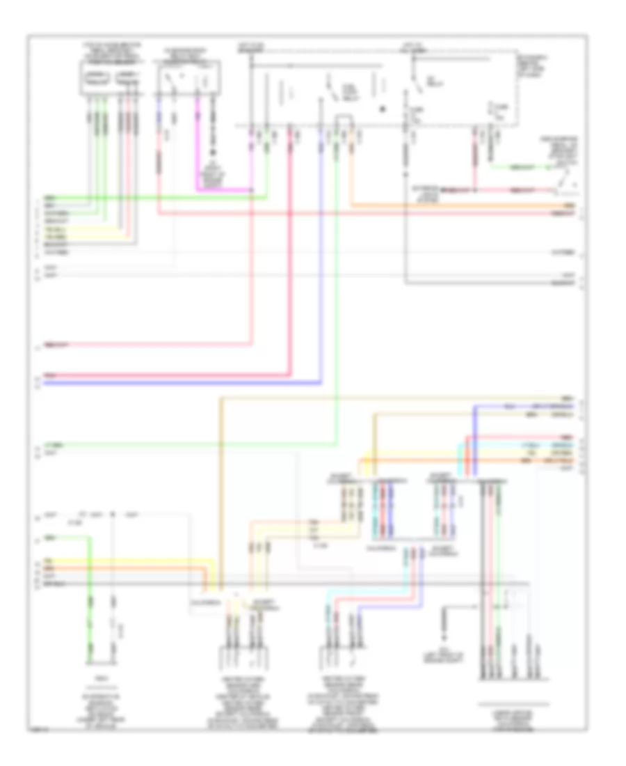
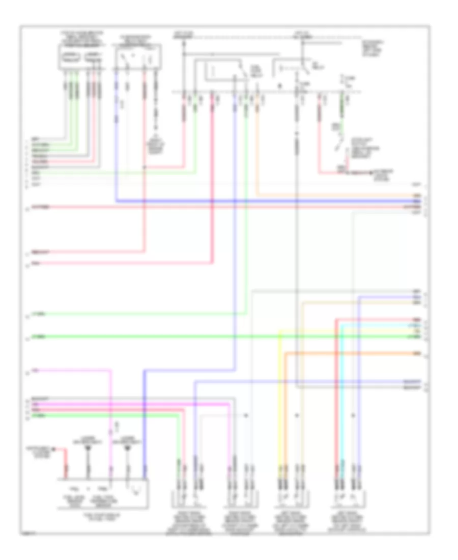
2.4L, Engine Performance Wiring Diagram (1 of 4) for Mitsubishi Outlander GT 2010

List of elements for 2.4L, Engine Performance Wiring Diagram (1 of 4) for Mitsubishi Outlander GT 2010:
- (in engine room relay box) throttle actuator control motor relay
- (under driver's seat) g18
- A-13
- Air conditioning system
- B-10
- B-11
- C-129
- Computer data lines system
- Cruise control system
- Engine compartment relay box (left side of engine compt)
- Engine control module (left rear corner of engine compt)
- Fuel level sensor (main)
- Fuel pump module (in fuel tank)
- Fuel tank differential pressure sensor (top of fuel tank)
- Fuel tank temperature sensor
- Fuse 10a
- Fuse 15a
- Fuse 20a
- Fuse 7.5a
- G12 (left front of engine compt)
- G15 (left side of engine compt)
- G4 (rear of engine compt)
- Hot at all times
- Instrument cluster system
- Mass airflow sensor (left rear of engine compt)
- Mfi relay
- Pnk
- Power steering pressure switch (right front of engine)
- Red
- Starting/ charging system
- Starting/charging system
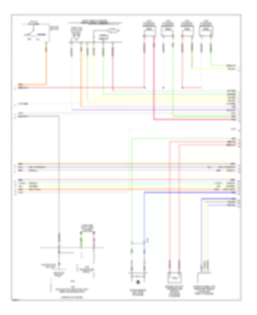
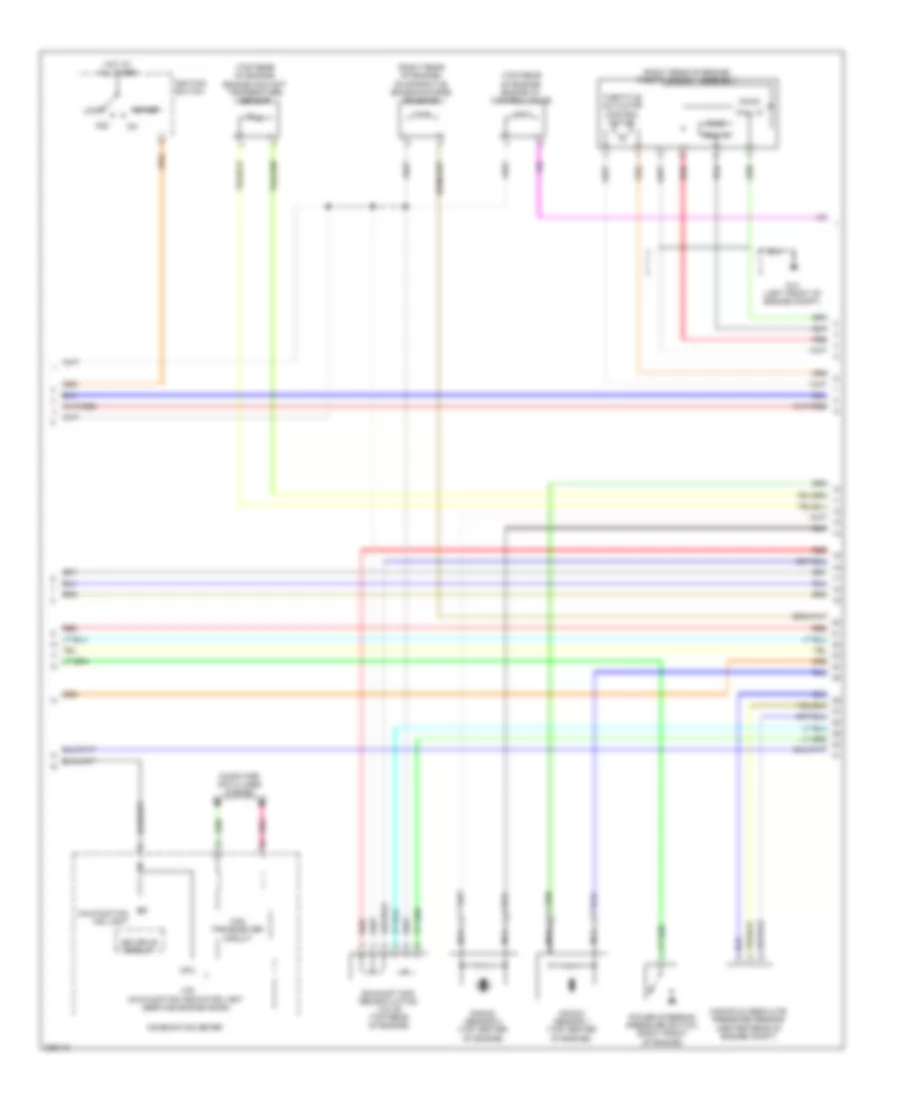
2.4L, Engine Performance Wiring Diagram (2 of 4) for Mitsubishi Outlander GT 2010
List of elements for 2.4L, Engine Performance Wiring Diagram (2 of 4) for Mitsubishi Outlander GT 2010:
- (above brake pedal, on bracket) stoplight switch
- (in engine room relay box) injector relay
- (main)
- (or red)
- (sub)
- (top of accelerator pedal bracket) accelerator pedal position sensor
- A-13
- C-129
- C-304
- C-307
- C-312
- C-314
- C-315
- C-317
- California
- D-113
- Etacs-ecu (behind left side of dash)
- Evaporative emission ventilation solenoid (under left rear of vehicle)
- Except california
- Exterior lights system
- Fuel pump relay
- Fuse 15a
- Fuse 7.5a
- G1 (right front of engine compt)
- G14 (left front of engine compt)
- Hall ic
- Heated oxygen sensor (3rd) (california) (center of vehicle) heated oxygen sensor (rear) (except california) (in exhaust, downstream of catalytic converter)
- Heated oxygen sensor (rear) (california) (in exhaust, downstream of catalytic converter) heated oxygen sensor (front) (except california) (in exhaust, upstream of catalytic converter)
- Hot at all times
- Hot in on or start
- Ig1 relay
- Linear air-fuel ratio sensor (california) (top of engine)
- Nca
- Pnk
- Red
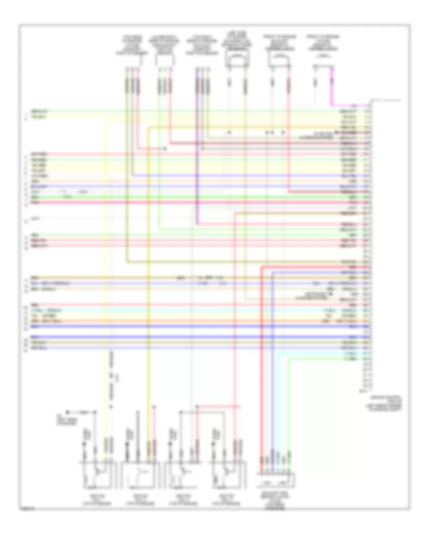
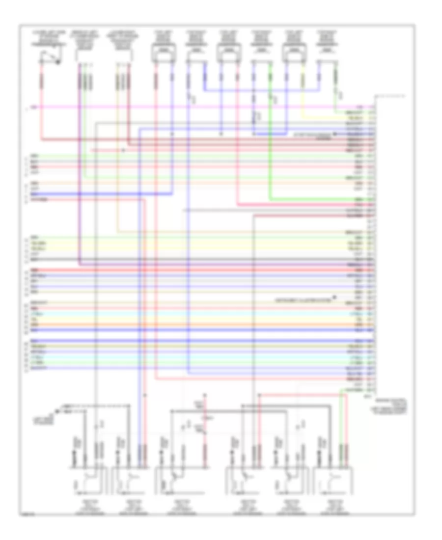
2.4L, Engine Performance Wiring Diagram (3 of 4) for Mitsubishi Outlander GT 2010
List of elements for 2.4L, Engine Performance Wiring Diagram (3 of 4) for Mitsubishi Outlander GT 2010:
- (main)
- (or red)
- (right rear of engine) throttle body assembly
- (sub)
- (top of engine) injector 1
- (top of engine) injector 2
- (top of engine) injector 3
- (top of engine) injector 4
- Acc
- B-24
- Can transceiver circuit
- Combination meter
- Computer data lines system
- Cpu
- Engine coolant temperature sensor (top rear of engine)
- Hall ic
- Hot at all times
- Ignition switch
- Knock sensor (left side of engine)
- Lcd (malfunction indicator light (service engine soon))
- Led drive circuit
- Lock
- Malfunction ind light
- Manifold absolute pressure sensor (lower left front of engine)
- Nca
- Pnk
- Red
- Start
- Throttle actuator control motor
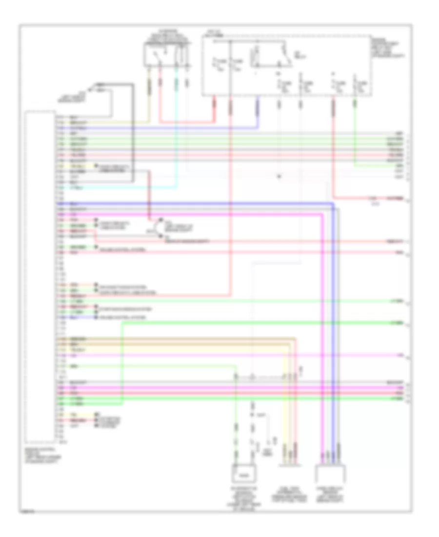
2.4L, Engine Performance Wiring Diagram (4 of 4) for Mitsubishi Outlander GT 2010
List of elements for 2.4L, Engine Performance Wiring Diagram (4 of 4) for Mitsubishi Outlander GT 2010:
- (front of engine) exhaust engine oil control valve
- (front of engine) intake engine oil control valve
- (left side of engine) evaporative emission purge solenoid
- (lower right rear of engine) crankshaft position sensor
- (or red)
- (top rear of engine) intake camshaft position sensor
- (top right rear of engine) exhaust camshaft position sensor
- A-13
- B-10
- C-129
- Engine control module (left rear corner of engine compt)
- Exhaust gas recirculation valve (top rear of engine)
- G3 (left rear of engine)
- Ignition coil 1 (top of engine)
- Ignition coil 2 (top of engine)
- Ignition coil 3 (top of engine)
- Ignition coil 4 (top of engine)
- Instrument cluster system
- Nca
- Plug spark
- Pnk
- Red
- Spark plug
- Starting/ charging system
3.0L
3.0L, Engine Performance Wiring Diagram (1 of 4) for Mitsubishi Outlander GT 2010
List of elements for 3.0L, Engine Performance Wiring Diagram (1 of 4) for Mitsubishi Outlander GT 2010:
- (in engine room relay box) throttle actuator control motor relay
- (not used)
- A-13
- Air conditioning system
- B-10
- B-11
- C-129
- Computer data lines system
- Cruise control system
- D-113
- D-30
- Engine compartment relay box (left side of engine compt)
- Engine control module (left rear corner of engine compt)
- Evaporative emission ventilation solenoid (under left rear of vehicle)
- Fuel tank differential pressure sensor (top of fuel tank)
- Fuse 10a
- Fuse 15a
- Fuse 20a
- Fuse 7.5a
- G12 (left front of engine compt)
- G15 (left side of engine compt)
- G4 (rear of engine compt)
- Hot at all times
- Mass airflow sensor (left rear of engine compt)
- Mfi relay
- Pnk
- Red
- Starting/ charging system
- Starting/charging system
3.0L, Engine Performance Wiring Diagram (2 of 4) for Mitsubishi Outlander GT 2010
List of elements for 3.0L, Engine Performance Wiring Diagram (2 of 4) for Mitsubishi Outlander GT 2010:
- (in engine room relay box) injector relay
- (main)
- (sub)
- (top of accelerator pedal bracket) accelerator pedal position sensor
- (under driver's seat) g18
- A-13
- C-129
- C-304
- C-307
- C-312
- C-314
- C-315
- C-317
- Etacs-ecu (behind left side of dash)
- Exterior lights system
- Fuel level sensor (main)
- Fuel pump module (in fuel tank)
- Fuel pump relay
- Fuel tank temperature sensor
- Fuse 15a
- Fuse 7.5a
- G1 (right front of engine compt)
- Hall ic
- Hot at all times
- Hot in on or start
- Ig1 relay
- Instrument cluster system
- Left bank heated oxygen sensor (front) (on left bank exhaust manifold)
- Left bank heated oxygen sensor (rear) (on left cylinder bank catalytic converter)
- Nca
- Pnk
- Red
- Right bank heated oxygen sensor (front) (in right cylinder bank exhaust manifold)
- Right bank heated oxygen sensor (rear) (downstream of right cylinder bank catalytic converter)
- Stoplight switch (above brake pedal, on bracket)
3.0L, Engine Performance Wiring Diagram (3 of 4) for Mitsubishi Outlander GT 2010
List of elements for 3.0L, Engine Performance Wiring Diagram (3 of 4) for Mitsubishi Outlander GT 2010:
- (main)
- (right rear of engine) evaporative emission purge solenoid
- (right rear of engine) throttle body assembly
- (sub)
- (top rear of engine) engine coolant temperature sensor
- (top rear of engine) engine oil control valve
- Acc
- Can transceiver circuit
- Combination meter
- Computer data lines system
- Cpu
- Exhaust gas recirculation valve (top rear of engine)
- G14 (left front of engine compt)
- Hall ic
- Hot at all times
- Ignition switch
- Knock sensor 1 (top center of engine)
- Knock sensor 2 (top center of engine)
- Lcd (malfunction indicator light (service engine soon))
- Led drive circuit
- Lock
- Malfunction ind light
- Manifold absolute pressure sensor (center rear of engine compt)
- Nca
- Pnk
- Power steering pressure switch (right front of engine)
- Red
- Start
- Throttle actuator control motor
3.0L, Engine Performance Wiring Diagram (4 of 4) for Mitsubishi Outlander GT 2010
List of elements for 3.0L, Engine Performance Wiring Diagram (4 of 4) for Mitsubishi Outlander GT 2010:
- (lower left side of engine) engine oil pressure switch
- (lower right front of engine) crankshaft position sensor
- (rear of left cylinder bank) camshaft position sensor
- (top left side of engine) injector 2
- (top left side of engine) injector 4
- (top left side of engine) injector 6
- (top right side of engine) injector 1
- (top right side of engine) injector 3
- (top right side of engine) injector 5
- B-10
- B-21
- Engine control module (left rear corner of engine compt)
- G3 (left rear of engine)
- Ignition coil 1 (top right side of engine)
- Ignition coil 2 (top left side of engine)
- Ignition coil 3 (top right side of engine)
- Ignition coil 4 (top left side of engine)
- Ignition coil 5 (top right side of engine)
- Ignition coil 6 (top left side of engine)
- Instrument cluster system
- Nca
- Plug spark
- Pnk
- Red
- Starting/charging system