ENGINE PERFORMANCE
2.4L
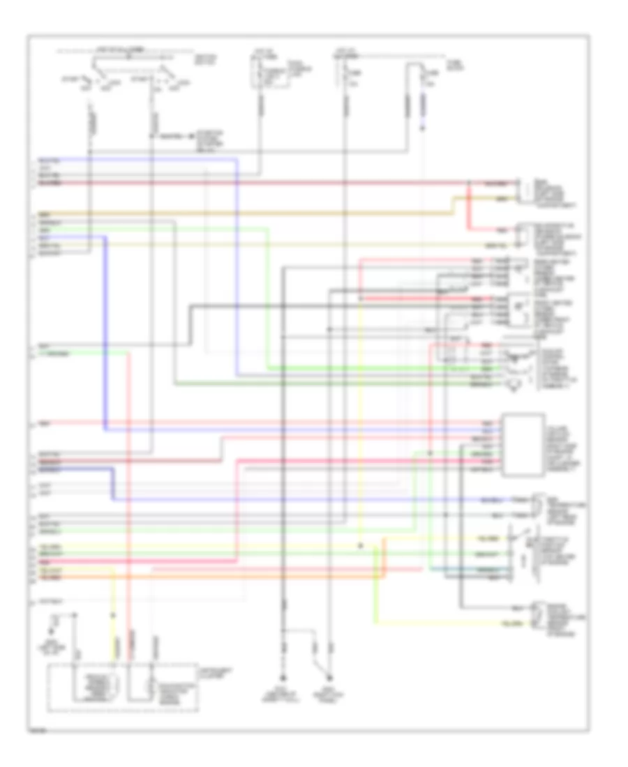
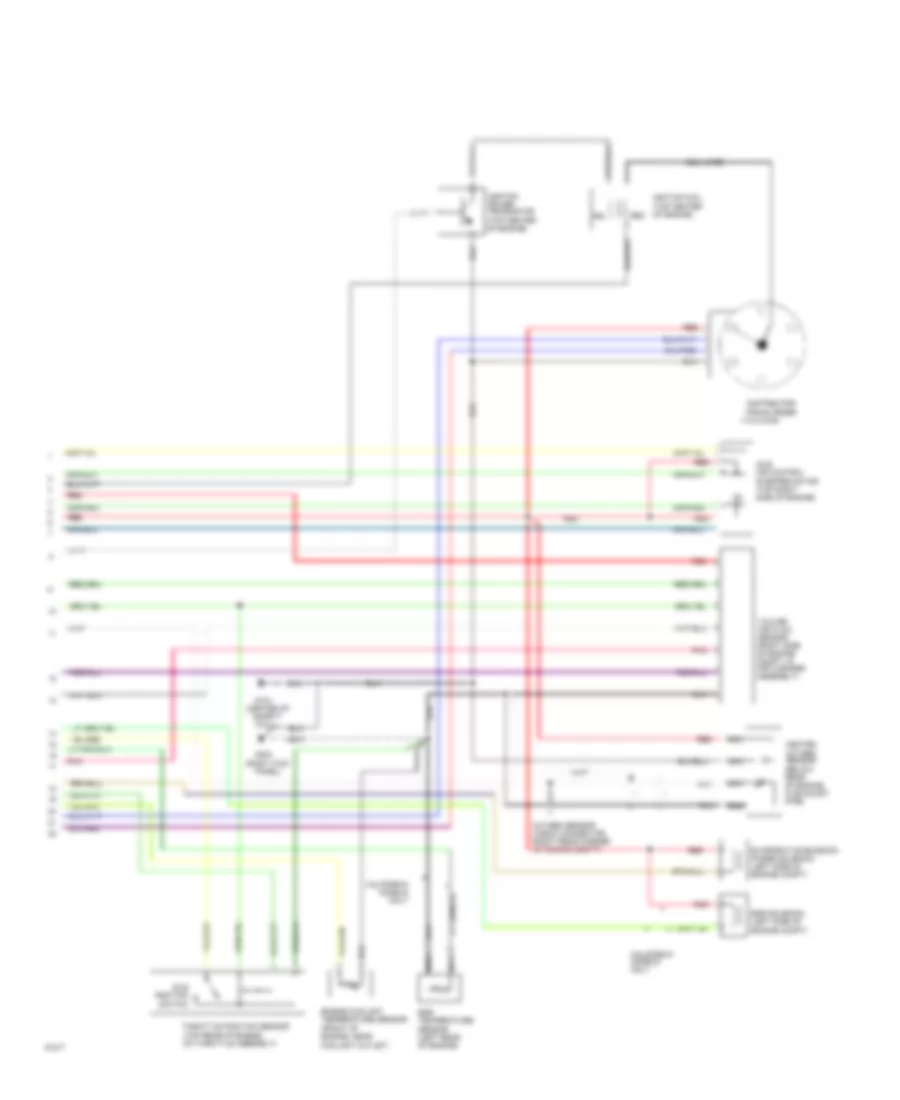
2.4L, Engine Performance Wiring Diagrams, California (1 of 2) for Mitsubishi Pickup Mighty Max 1994

List of elements for 2.4L, Engine Performance Wiring Diagrams, California (1 of 2) for Mitsubishi Pickup Mighty Max 1994:
- A/c engine coolant temperature switch
- A/t
- Air conditioning compressor clutch relay
- Coil wire
- Data link connector (left side of i/p)
- Distributor firing order (1-3-4-2)
- Engine control relay (below right side of dash, at kick panel)
- Fuel injectors
- Fuel pump (in top side of fuel tank)
- Fuel pump check connector (right rear corner of engine compt)
- G106 (behind left headlamp)
- G121 (center of safety wall)
- G202 (left side of i/p)
- G203 (right kick panel)
- Ignition coil (top center of engine)
- Ignition power transistor (top center of engine)
- Ignition timing adjustment connector (right rear corner of engine compt)
- M/t
- Pnk
- Powertrain control module (below right side of dash, at kick panel)
- Pri
- Red
- Sec
- Starting system (starter relay)
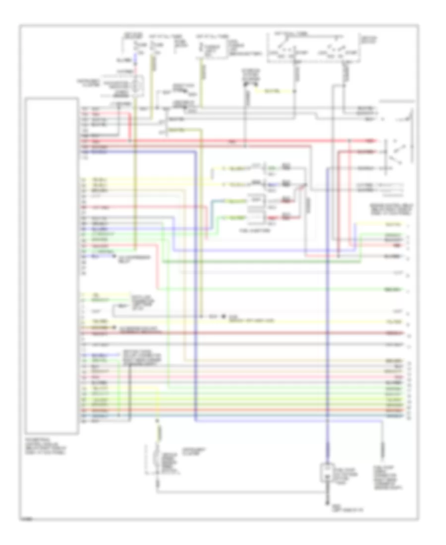
2.4L, Engine Performance Wiring Diagrams, California (2 of 2) for Mitsubishi Pickup Mighty Max 1994
List of elements for 2.4L, Engine Performance Wiring Diagrams, California (2 of 2) for Mitsubishi Pickup Mighty Max 1994:
- (right side of engine compt, in air cleaner assembly)
- Acc
- Egr solenoid (left side of engine compartment)
- Egr temperature sensor (left rear of engine)
- Engine coolant temperature sensor (front of engine)
- Evaporative emission purge solenoid (left side of engine compartment)
- Front heated oxygen sensor (under front of vehicle, in exhaust pipe)
- Fuse 10a
- Fuse 15a
- Fuse block
- Fusible link 2 20a
- G121 (center of safety wall)
- G202 (left side of i/p)
- G203 (right kick panel)
- Hall ic
- Hot at all times
- Idle air control motor (top rear of engine, on throttle assembly)
- Idle sw
- Ignition switch
- Instrument cluster
- Lock
- Main fusible link
- Malfunction indicator (check engine)
- Nca
- Pnk
- Rear heated oxygen sensor (under center of vehicle, in exhaust pipe)
- Red
- Start
- Starting system (starter relay)
- Throttle position sensor (top center of engine)
- Vehicle speed sensor (reed switch)
- Volume air flow sensor
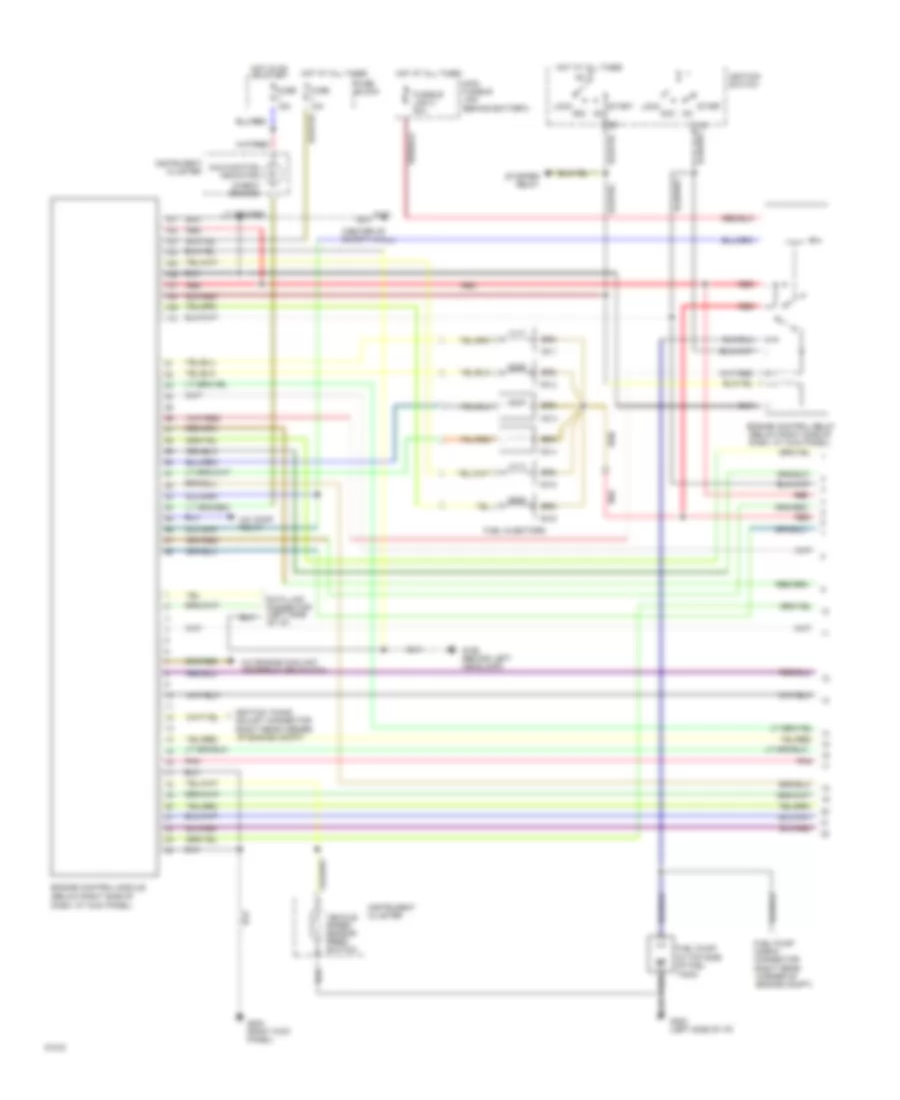
2.4L, Engine Performance Wiring Diagrams, Federal (1 of 2) for Mitsubishi Pickup Mighty Max 1994
List of elements for 2.4L, Engine Performance Wiring Diagrams, Federal (1 of 2) for Mitsubishi Pickup Mighty Max 1994:
-
- (center of safety wall)
- (check engine)
- (right kick panel)
- A/c compressor relay
- A/c engine coolant temperature switch
- A/t
- Acc
- Cluster
- Dash, at kick panel)
- Data link connector (left side of i/p)
- Engine control relay (below right side of dash, at kick panel)
- Fuel injectors
- Fuel pump (in top side of fuel
- Fuel pump check connector (right rear corner of engine compt)
- Fuse 10a
- Fuse 15a
- Fuse block
- Fusible link 2 20a
- G106 (behind left headlamp)
- G121
- G202 (left side of i/p)
- G203
- Hot at all times
- Hot in on or start
- Ig1
- Ignition switch
- Ignition timing adjust connector (right rear corner of engine compt)
- Instrument
- Instrument cluster
- Lock
- M/t
- Main fusible link (behind battery)
- Malfunction indicator
- No.1
- No.2
- No.3
- No.4
- Pnk
- Pnk
- Powertrain control module (below right side of
- Red
- Red
- Start
- Starting system (starter relay)
- Tank)
- Vehicle speed sensor (reed switch)
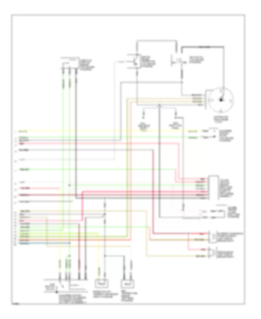
2.4L, Engine Performance Wiring Diagrams, Federal (2 of 2) for Mitsubishi Pickup Mighty Max 1994
List of elements for 2.4L, Engine Performance Wiring Diagrams, Federal (2 of 2) for Mitsubishi Pickup Mighty Max 1994:
-
- (center of safety wall)
- (front of engine)
- (top center of engine)
- Coil wire
- Distributor firing order (1-3-4-2)
- Egr solenoid (left side of engine compt)
- Egr temperature sensor (left rear of engine)
- Engine coolant temperature sensor
- Evaporative emission purge solenoid (left side of engine compt)
- G121
- G203 (right kick panel)
- Idle position switch
- Idle speed control motor (top center of engine)
- Idle speed control motor position sensor (top rear of engine, on throttle assembly)
- Ignition coil
- Ignition power transistor (top center of engine)
- Nca
- Oxygen sensor (lower right side of engine)
- Pnk
- Pri
- Red
- Sec
- Throttle position sensor (top center of engine)
- Volume air flow sensor (right side of engine compt, in air cleaner assembly)
3.0L
3.0L, Engine Performance Wiring Diagrams (1 of 2) for Mitsubishi Pickup Mighty Max 1994
List of elements for 3.0L, Engine Performance Wiring Diagrams (1 of 2) for Mitsubishi Pickup Mighty Max 1994:
- (center of safety wall)
- (check engine)
- (right kick
- A/c comp relay
- A/c engine coolant temperature switch
- Acc
- Cluster
- Dash, at kick panel)
- Data link connector (left side of i/p)
- Engine control module (below right side of
- Engine control relay (below right side of dash, at kick panel)
- Fuel injectors
- Fuel pump (in top side of fuel
- Fuel pump check connector (right rear corner of engine compt)
- Fuse 10a
- Fuse 15a
- Fuse block
- Fusible link 2 20a
- G106 (behind left headlamp)
- G121
- G202 (left side of i/p)
- G203
- Hot at all times
- Hot in on or start
- Ig1
- Ignition switch
- Ignition timing adjust connector (right rear corner of engine compt)
- Instrument
- Instrument cluster
- Lock
- Main fusible link (behind battery)
- Malfunction indicator
- No.1
- No.2
- No.3
- No.4
- No.5
- No.6
- Panel)
- Pnk
- Pnk
- Red
- Red
- Start
- Starter relay
- Tank)
- Vehicle speed sensor (reed switch)
3.0L, Engine Performance Wiring Diagrams (2 of 2) for Mitsubishi Pickup Mighty Max 1994
List of elements for 3.0L, Engine Performance Wiring Diagrams (2 of 2) for Mitsubishi Pickup Mighty Max 1994:
- (1-2-3-4-5-6)
- (center of safety wall)
- (front of engine, near coolant outlet)
- (right kick panel)
- (top center of engine)
- California
- California models only
- Coil wire
- Distributor firing order
- Egr solenoid (left side of engine compt)
- Egr temperature sensor (left rear of engine)
- Engine coolant temperature sensor
- Evaporative emission purge solenoid (left side of engine compt)
- G121
- G203
- Heated oxygen sensor (below rear of engine, in exhaust pipe)
- Idle air control stepper motor (top right side of engine)
- Idle position switch
- Ignition coil
- Ignition power transistor (top center of engine)
- Models
- Nca
- Only
- Oxygen sensor check connector (right rear corner of engine compt)
- Pnk
- Pri
- Red
- Sec
- Throttle position sensor (top rear of engine, on throttle assembly)
- Volume air flow sensor (right side of engine compt, in air cleaner assembly)