ENGINE PERFORMANCE
2.4L
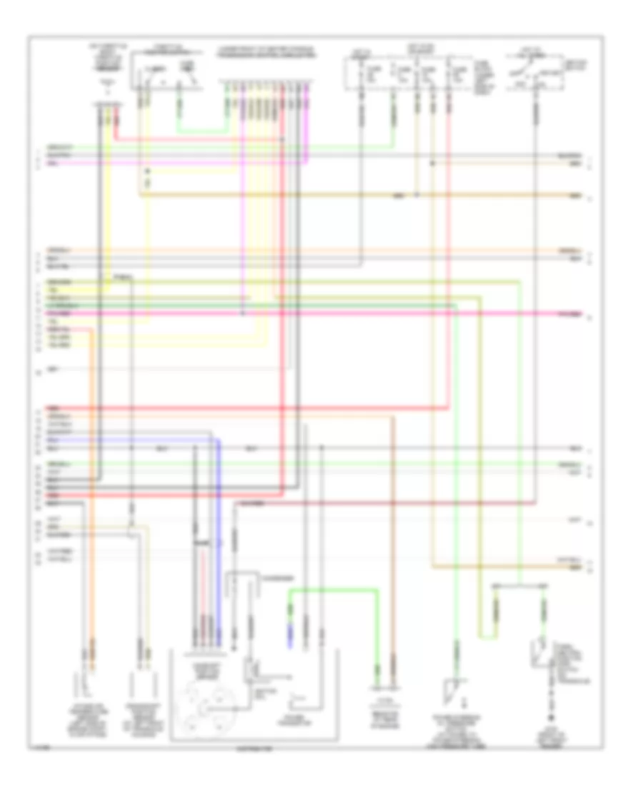
2.4L, Engine Performance Wiring Diagrams (1 of 3) for Nissan Altima GXE 2001

List of elements for 2.4L, Engine Performance Wiring Diagrams (1 of 3) for Nissan Altima GXE 2001:
- (behind left side of dash) data link connector (dlc)
- A/c system
- Abs control unit (behind left kick panel)
- Acrly
- Air con
- Atck
- Avcc
- Batt
- Cooling fans system
- Defogger system
- Dt1
- Dt2
- Dt3
- Ecm relay (behind instrument panel lower cover)
- Egr temperature sensor (near base of egr valve)
- Egrts
- Engine control module (ecm) (behind instrument panel lower cover)
- Engine coolant temperature sensor (on left side of engine, near fuel inj 1)
- Evap
- Evap canister purge volume control solenoid valve (top right side of engine)
- Evap control system pressure sensor (under left rear corner of vehicle)
- Fgage+
- Fgage-
- Fpr
- Ftemp
- Ftpres
- Fuel level
- Fuel level sensor unit (in fuel tank)
- Fuel temp
- Fuse & fusible link box (on left side of engine compt)
- Fuse 10a
- G131 (on intake manifold)
- G904 (left "c" pillar)
- Gnd-a
- Gnd-c
- Gnd-i
- H/fan
- H/lamp
- Headlight system
- Hot at all times
- Idle
- Ign
- Ignck
- Ignsw
- Imline
- Instrument cluster system (tachometer)
- Kline
- Knk
- Knock sensor (on right side of engine)
- Led-r
- Mass airflow (maf) sensor (left side of engine compt, in air intake)
- Nats immu
- Nca
- Neut
- O2sf
- O2sr
- Pdsw
- Pos
- Pwst
- Qa+
- Qa-
- R/def
- Red
- Ref
- Rflh
- Rfrh
- Rgc/s
- Scirx
- Scitx
- Ssoff
- Stsw
- Tacho
- Tamb
- Tasw
- Tvo1
- Tvoo
- Vsp
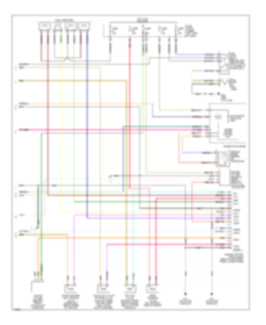
2.4L, Engine Performance Wiring Diagrams (2 of 3) for Nissan Altima GXE 2001
List of elements for 2.4L, Engine Performance Wiring Diagrams (2 of 3) for Nissan Altima GXE 2001:
- (on throttle body) throttle position sensor
- (under front of center console) transmission control module (tcm)
- A/t
- Acc
- Camshaft position sensor
- Closed
- Condenser
- Crankshaft position sensor (at left front of transaxle housing)
- Distributor
- Fuse 10a
- Fuse block (under left side of dash)
- G100 (front of left front fender)
- Hot at all times
- Hot in on or start
- Hot in start
- Ignition coil
- Ignition switch
- Intake air temperature sensor (left side of engine compt, in air intake)
- M/t
- Nca
- Off
- Park/ neutral position (pnp) switch (on transaxle)
- Power steering oil pressure switch (attached to power steering high pressure tube)
- Power transistor
- Red
- Resistor (at rear of engine)
- Start
- Throttle position switch
- Wide open
2.4L, Engine Performance Wiring Diagrams (3 of 3) for Nissan Altima GXE 2001
List of elements for 2.4L, Engine Performance Wiring Diagrams (3 of 3) for Nissan Altima GXE 2001:
- 10n
- 13k
- 1o1
- Cdcv
- Combination meter
- Crtn
- Cvbv
- Egr
- Egrc solenoid valve (on top right side of engine)
- Engine control module (ecm) (behind instrument panel lower cover)
- Evap canister vent control valve (under left rear corner of vehicle)
- Fuel injectors
- Fuel pump (in fuel tank)
- Fuel pump relay (behind left side of dash, attached to fuse block)
- Fuse 10a
- Fuse 15a
- Fuse block (under left side of dash)
- G131 (on intake manifold)
- G904 (left "c" pillar)
- Gnd-e
- Heated oxygen sensor 1 (front) (on exhaust manifold)
- Heated oxygen sensor 2 (rear) (rear of catalytic converter)
- Hot in on or start
- Iacv-aac valve (on right front side of engine, below intake manifold)
- Inj 1
- Inj 2
- Inj 3
- Inj 4
- Isc
- Malfunction indicator lamp
- Nca
- O2hf
- O2hr
- Pnk
- Red
- Unified meter control unit
- Vacuum cut valve by-pass valve (on evap purge line, between fuel tank & evap canister)
- Vehicle speed sensor (on transaxle)