ENGINE PERFORMANCE
2.5L
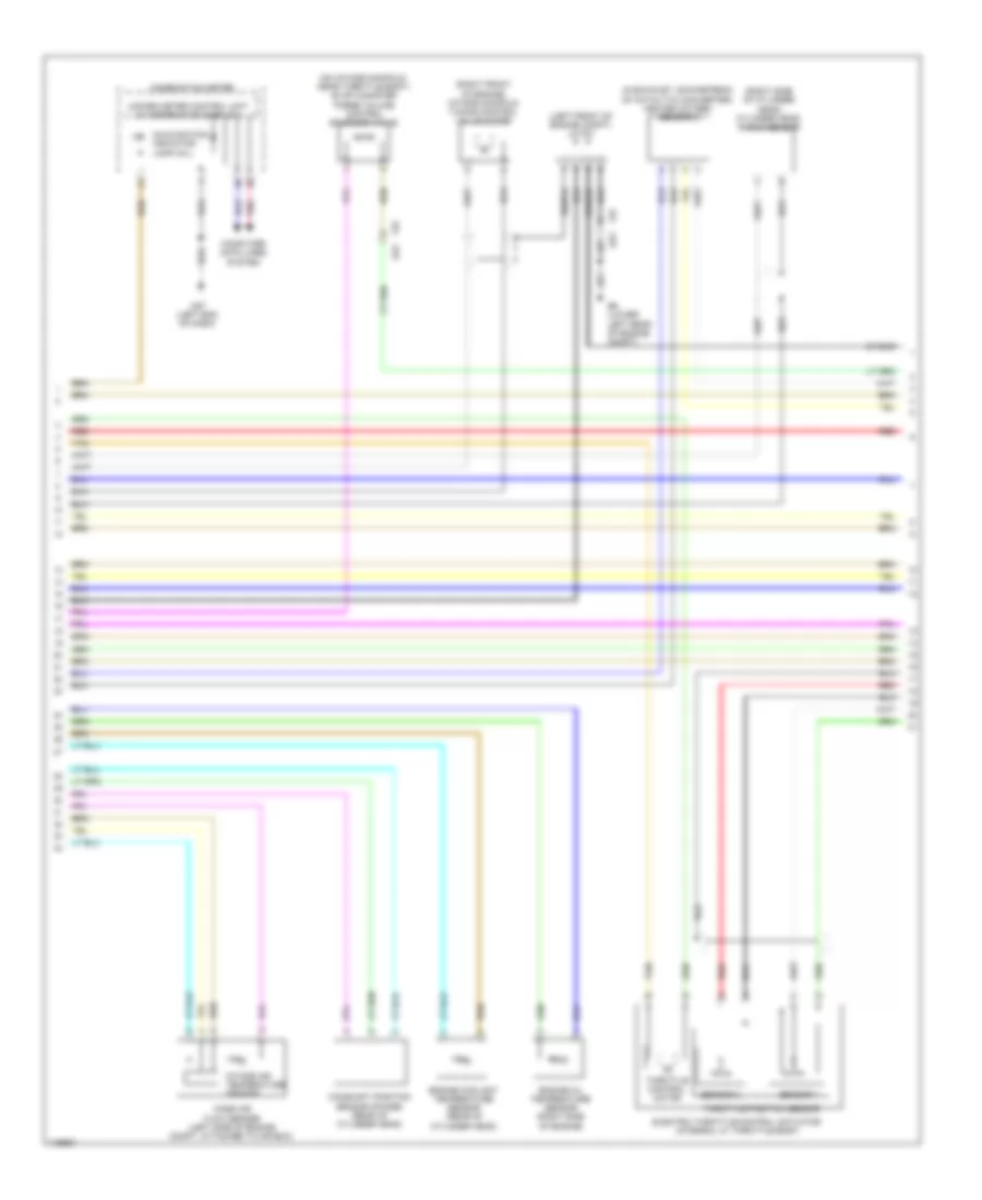
2.5L, Engine Performance Wiring Diagram (1 of 6) for Nissan Altima S 2014

List of elements for 2.5L, Engine Performance Wiring Diagram (1 of 6) for Nissan Altima S 2014:
- (left end of dash) j/c e10
- (lower left rear of engine compt) e9
- (top of brake pedal assembly) (w/ ascd) brake pedal position switch
- A/f sens 1
- Air fuel ration (a/f) sensor 1 (on exhaust manifold)
- California
- Camsh pstn sens (phase)
- Ctrl pstn sens
- Ctrl sold vlv
- E23
- Ecm (near battery)
- Ecm gnd
- Eng colt temp sens
- Eng oil prss sens
- Eng oil temp sens
- Engine oil pressure sensor (right front of engine)
- Except california
- Exhaust valve timing control position sensor (rear of cylinder head)
- F14
- F25
- F91
- Fuel inj 1
- Fuel inj 2
- Fuel inj 3
- Fuel inj 4
- Fuel pump rly
- Fuse 10 10a
- Fuse 30 10a
- Fuse 31 5a
- Fuse block (j/b) (lower left end of dash)
- Hot at all times
- Hot w/ ignition relay 2 energized
- Htd oxygen sens 2
- Intak air temp sens
- J/c e08 (left end of dash)
- Knock snsr
- Mass air flow sens
- Mtr (opn)
- Mtr pwr sply
- Red
- Sens gnd
- Sens per sply
- Sens pwr sply
- Shield
- Snsr gnd
- Stop lamp relay (fuse/fusible link & relay box)
- Stop light switch (top of brake pedal assembly)
- Tan
- Thrtl ctrl mtr (cl)
- Thrtl ctrl mtr (opn)
- Thrtl ctrl mtr pwr sply
- Thrtl ctrl mtr rly
- Tuning vlv mtr (cl)
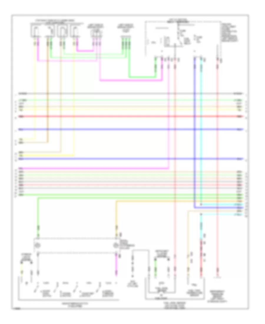
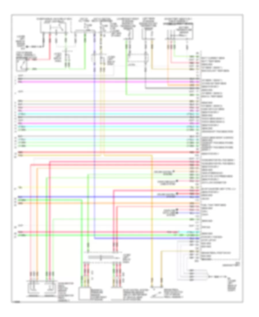
2.5L, Engine Performance Wiring Diagram (2 of 6) for Nissan Altima S 2014
List of elements for 2.5L, Engine Performance Wiring Diagram (2 of 6) for Nissan Altima S 2014:
- (in exhaust, downstream of catalytic converter) heated oxygen sensor 2
- (left front of engine compt) j/c f01
- (on intake manifold, near throttle body) evap canister purge volume control solenoid valve
- (right front of engine) intake manifold tuning control valve motor
- (right side of cylinder head) cylinder head knock sensor
- Camshaft position sensor (phase) (rear of cylinder head)
- Combination meter
- Computer data lines system
- E23
- E9 (lower left rear of engine compt)
- Electric throttle control actuator (integral w/ throttle body)
- Engine coolant temperature sensor (rear of cylinder head)
- Engine oil temperature sensor (right side of engine)
- F25
- Intake air temperature sensor
- M57 (left end of dash)
- Malfunction indicator lamp (mil)
- Mass air flow sensor (left side of engine compt, attached to air box)
- Pnk
- Red
- Sensor 1
- Sensor 2
- Shield
- Tan
- Throttle control motor
- Throttle position sensor
- Unified meter control unit (w/ information display)
2.5L, Engine Performance Wiring Diagram (3 of 6) for Nissan Altima S 2014
List of elements for 2.5L, Engine Performance Wiring Diagram (3 of 6) for Nissan Altima S 2014:
- (left side of engine compt) j/c f07
- (left side of engine compt) j/c f08
- (top right side of cylinder head) fuel injectors
- 44g
- 81j
- Accel/ resume switch
- Ascd steering switch (if equipped)
- B10
- B19 (at left "c" pillar)
- Cancel switch
- Coast/set switch
- Cpu
- E18
- E201
- E29
- E30
- E63
- F83
- F84
- Fuel level sensor
- Fuel level sensor unit & fuel pump (top of fuel tank)
- Fuel pump
- Fuel pump relay
- Fuel tank temperature sensor
- Fuse 10a
- Fuse 15a
- Hot w/ ignition relay 1 energized
- Instrument cluster system
- Interior lights system
- Ipdm e/r (intelligent power distribution module engine room) (left rear of engine compt)
- M30
- M88
- On/off (main) switch
- Pnk
- Red
- Refrigerant pressure sensor (left front of engine compt)
- Shield
- Spiral cable (in steering column)
- Tan
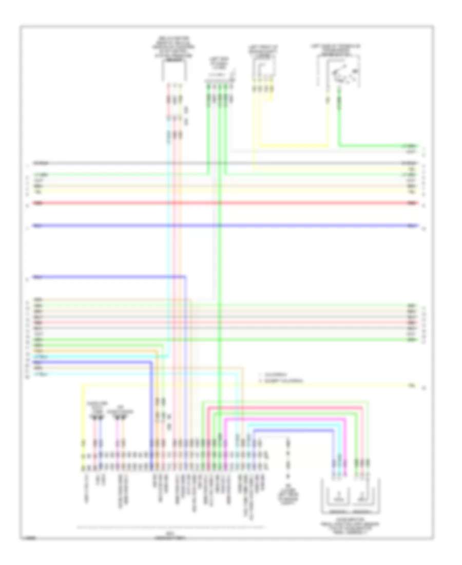
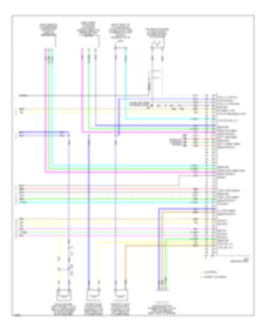
2.5L, Engine Performance Wiring Diagram (4 of 6) for Nissan Altima S 2014
List of elements for 2.5L, Engine Performance Wiring Diagram (4 of 6) for Nissan Altima S 2014:
- (below center rear of vehicle, near evap canister) evap control system pressure sensor
- (left end of dash) j/c e08
- (left front of engine compt) j/c f02
- (left side of transaxle) transmission range switch
- (lower left rear of engine compt)
- 42g
- 43g
- Acc pedal post sens 1
- Accelerator pedal position (app) sensor (top of accelerator pedal assembly)
- Accl pdl sens 2
- Air conditioning system
- Ascd strg sw
- B10
- Brk pdl post sens
- California
- Can-h
- Can-l
- Computer data lines system
- E10
- E29
- E30
- E31
- Ecm (near battery)
- Ecm gnd
- Except california
- Fuel tank temp sens
- Ign sw
- Pnk
- Pnp sig
- Press sens
- Pwr sply
- Red
- Refrg prss sens
- Sens gnd
- Sens pwr sply
- Sensor 1
- Sensor 2
- Shield
- Snsr gnd
- Stp lp sw
- Tan
- Vent ctrl vlv
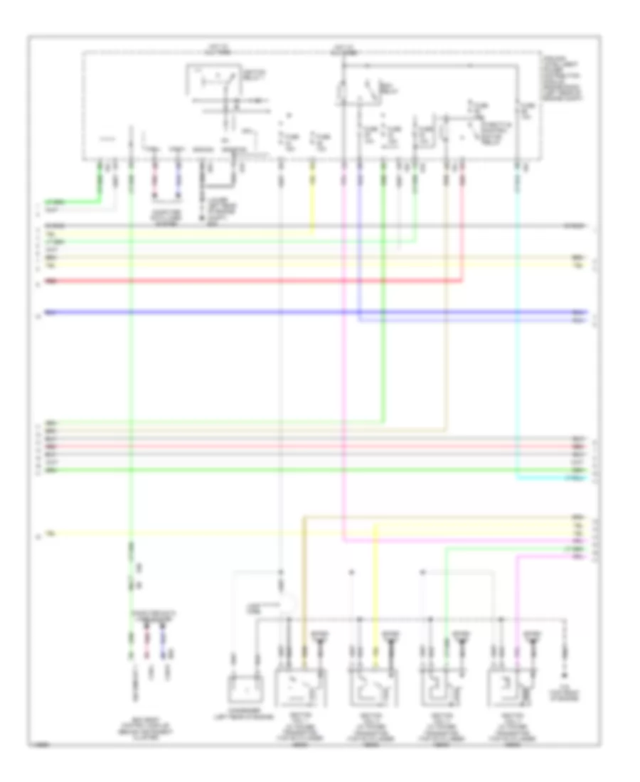
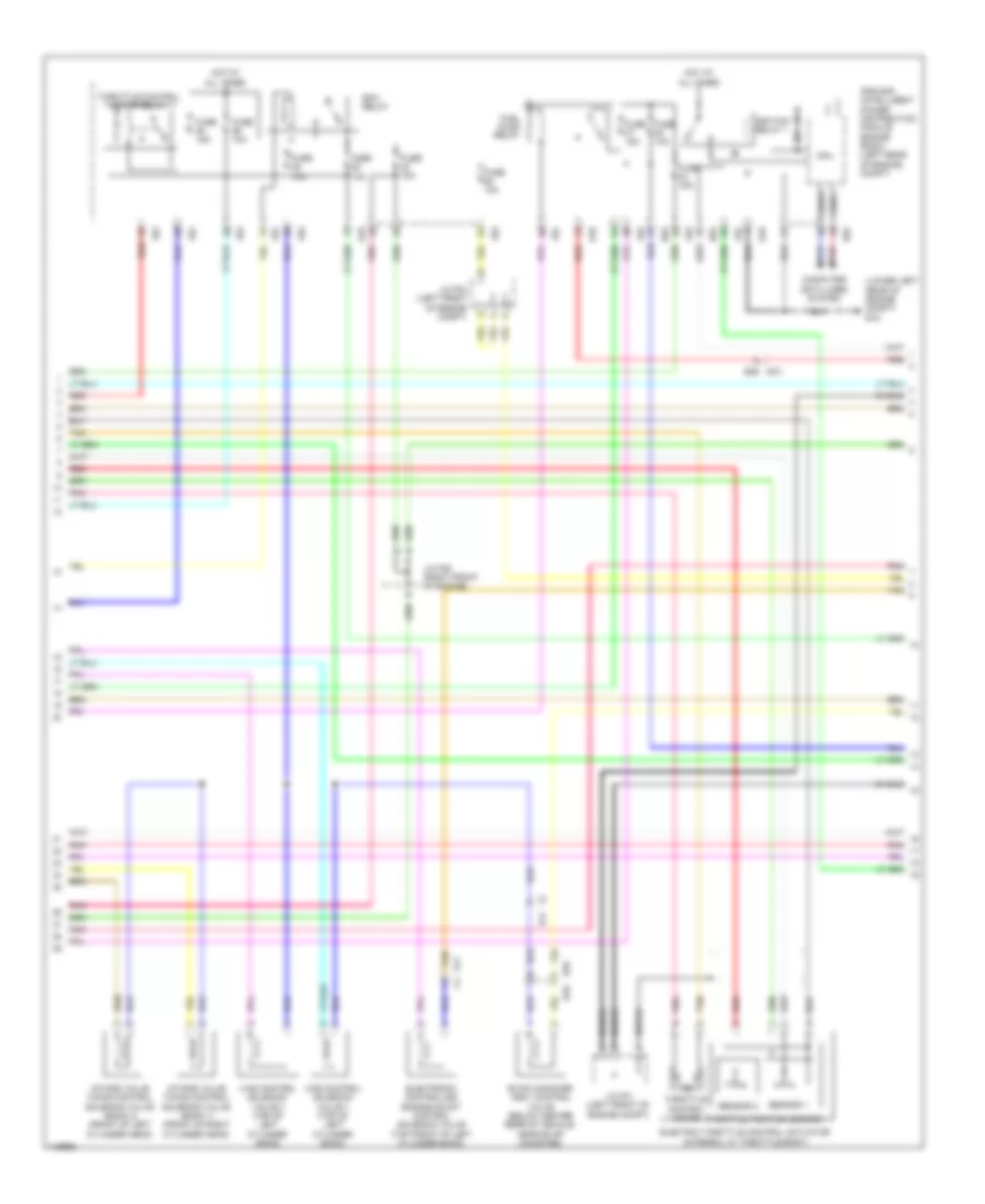
2.5L, Engine Performance Wiring Diagram (5 of 6) for Nissan Altima S 2014
List of elements for 2.5L, Engine Performance Wiring Diagram (5 of 6) for Nissan Altima S 2014:
- (lower left rear of engine compt) e15
- 36g
- Bcm (body control module) (behind instrument cluster)
- Can-h
- Can-l
- Computer data lines system
- Condenser (left rear of engine)
- Cpu
- E18
- E30
- E63
- Ecm relay
- F15 (top front of engine)
- F83
- F84
- Fuse 10a
- Fuse 15a
- Gnd-pwr
- Gnd-sig
- Hot at all times
- Ig+
- Ign usm out 1
- Ignition coil 1 (w/ power transistor) (top of cylinder head)
- Ignition coil 2 (w/ power transistor) (top of cylinder head)
- Ignition coil 3 (w/ power transistor) (top of cylinder head)
- Ignition coil 4 (w/ power transistor) (top of cylinder head)
- Ignition relay 1
- Ipdm e/r (intelligent power distribution module engine room) (left rear of engine compt)
- Loop wire
- M18
- Nca
- Pnk
- Red
- Shield
- Spark plug
- Throttle control motor relay
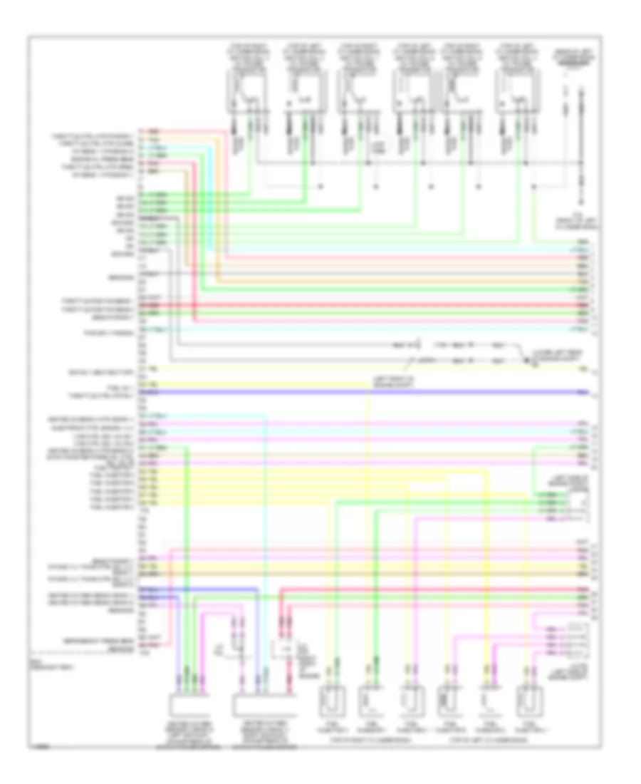
2.5L, Engine Performance Wiring Diagram (6 of 6) for Nissan Altima S 2014
List of elements for 2.5L, Engine Performance Wiring Diagram (6 of 6) for Nissan Altima S 2014:
- (lower left rear of engine compt) e9
- (right front of cylinder bank) intake valve timing intermediate lock control solenoid valve
- (right front of engine) (california) manifold absolute pressure (map) sensor
- (right rear of cylinder head) crankshaft position sensor (pos)
- (top rear of engine) intake manifold runner control valve motor
- A/f sens 1 htr
- B10
- Batt currnt sens
- Batt temp sens
- California
- Crksh post sens (pos)
- Ctrl sol vlv
- Ctrl vlv mtr (cl)
- Ctrl vlv mtr (opn)
- E11
- E23
- E29
- Ecm (near battery)
- Ecm gnd
- Ecm rly
- Evap canister vent control valve (below center rear of vehicle, near evap canister)
- Except california
- Exhaust valve timing control solenoid valve (left front of cylinder head)
- F13
- F25
- F90
- Htd oxygen sens 2 htr
- Ign sig 1
- Ign sig 2
- Ign sig 3
- Ign sig 4
- Intake manifold runner control valve position sensor (right front of engine)
- Intake valve timing control solenoid valve (right front of cylinder head)
- Lck ctrl sol vlv
- Mtr pwr sply
- Prss (map) sens
- Pwr sply
- Red
- Sens gnd
- Sens pwr sply
- Shield
- Starting/ charging system
- Thrtl post sens 1
- Thrtl post sens 2
- Vlv pstn sens
3.5L
3.5L, Engine Performance Wiring Diagram (1 of 4) for Nissan Altima S 2014
List of elements for 3.5L, Engine Performance Wiring Diagram (1 of 4) for Nissan Altima S 2014:
- (left front of engine compt)
- (left side of engine compt) j/c f07
- (lower left rear of engine compt) e9
- (rear of left cylinder bank) condenser
- (top of left cylinder bank)
- (top of left cylinder bank) ignition coil 2 (w/ power transistor)
- (top of left cylinder bank) ignition coil 4 (w/ power transistor)
- (top of left cylinder bank) ignition coil 6 (w/ power transistor)
- (top of right cylinder bank)
- (top of right cylinder bank) ignition coil 1 (w/ power transistor)
- (top of right cylinder bank) ignition coil 3 (w/ power transistor)
- (top of right cylinder bank) ignition coil 5 (w/ power transistor)
- A/f sens 1 htr (bank 1)
- A/f sens 1 htr (bank 2)
- Ecm (near battery)
- Ecm gnd
- Ecm rly (self shut-off)
- Electronic ctrl eng sol vlv
- Engine oil press sens
- F15 (front of left cylinder bank)
- F78
- F79
- Fuel inj 1
- Fuel injector 1
- Fuel injector 2
- Fuel injector 3
- Fuel injector 4
- Fuel injector 5
- Fuel injector 6
- Fuel pump rly
- Heated o2 sens 2 htr 1(bank 1)
- Heated o2 sens 2 htr 2(bank 2) evap canister purge vol ctrl sol valve
- Heated oxygen sens 2 (bank 1)
- Heated oxygen sens 2 (bank 2)
- Heated oxygen sensor 2 (bank 1) (right exhaust, downstream of catalytic converter)
- Heated oxygen sensor 2 (bank 2) (left exhaust, downstream of catalytic converter)
- Ign
- Ign sig
- Intake vlv timing ctrl sol vlv (bank 2)
- J/c f01
- J/c f04
- J/c f08 (left side of engine compt)
- J/c f09 (right front of engine)
- Loop wire
- Nca
- Plug spark
- Pnk
- Pwr sply for ecm
- Red
- Refrigerant press sens
- Sens gnd
- Sens pwr sply
- Sens pwr sply intake vlv timing ctrl sol vlv (bank 1)
- Spark plug
- Tan
- Throttle ctrl mtr (close)
- Throttle ctrl mtr (open)
- Throttle ctrl mtr pwr sply
- Throttle ctrl mtr rly
- Throttle position sens 1
- Throttle position sens 2
- Vias ctrl sol valve 1
- Vias ctrl sol valve 2
3.5L, Engine Performance Wiring Diagram (2 of 4) for Nissan Altima S 2014
List of elements for 3.5L, Engine Performance Wiring Diagram (2 of 4) for Nissan Altima S 2014:
- (lower left rear of engine compt) e15
- Can-h
- Can-l
- Computer data lines system
- Cpu
- E11 f2
- E18
- E29 b10
- E63
- Ecm relay
- Electric throttle control actuator (integral w/ throttle body)
- Electronic controlled engine mount control solenoid valve (top front of left cylinder bank)
- Evap canister vent control valve (below center rear of vehicle, near evap canister)
- F2 e11
- F83
- F84
- Fuel pump relay
- Fuse 10a
- Fuse 15a
- Hot at all times
- Ignition relay 1
- Intake valve timing control solenoid valve (bank 1) (front of right cylinder head)
- Intake valve timing control solenoid valve (bank 2) (front of left cylinder head)
- Ipdm e/r (intelligent power distribution module engine room) (left rear of engine compt)
- J/c f01 (left front of engine compt)
- J/c f02 (left front of engine compt)
- J/c f09 (right front of engine)
- Pnk
- Red
- Sensor 1
- Sensor 2
- Shield
- Tan
- Throttle control motor
- Throttle control motor relay
- Throttle position sensor
- Vias control solenoid valve 1 (top of left cylinder bank)
- Vias control solenoid valve 2 (top of left cylinder bank)
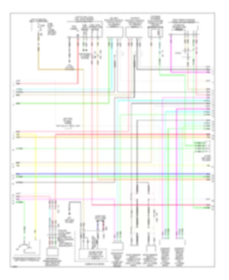
3.5L, Engine Performance Wiring Diagram (3 of 4) for Nissan Altima S 2014
List of elements for 3.5L, Engine Performance Wiring Diagram (3 of 4) for Nissan Altima S 2014:
- (left end of dash) j/c e08
- (on left exhaust manifold) air fuel ratio (a/f) sensor (bank 2)
- (on right exhaust manifold) air fuel ratio (a/f) sensor (bank 1)
- (right rear of engine) mass air flow sensor
- (top of fuel tank) fuel level sensor unit & fuel pump
- (top rear of engine) evap canister purge volume control solenoid valve
- 81j
- B1 m6
- B10 e29
- B19 (at left "c" pillar)
- Camshaft position sensor (phase) (bank 1) (rear of right cylinder bank)
- Camshaft position sensor (phase) (bank 2) (rear of left cylinder bank)
- Can-h
- Can-l
- Combination meter
- Computer data lines system
- Crankshaft position sensor (pos) (lower left rear of engine)
- E63
- F1 e3
- F2 e11
- F76 f201
- Fuel level sensor
- Fuel pump
- Fuel tank temperature sensor
- Fuse 5a
- Fuse block (j/b) (lower left end of dash)
- Gnd1
- Hot w/ ignition relay 2 energized
- Ign
- Instrument cluster system
- Intake air temperature sensor
- Ipdm e/r (intelligent power distribution e201 module engine room) (left rear of engine compt)
- J/c e08 (left end of dash)
- J/c f04
- Knock sensor (bank 1) (under intake manifold, in right cylinder bank)
- Knock sensor (bank 2) (under intake manifold, in left cylinder bank)
- M24
- M57 (left end of dash)
- Malfunction indicator lamp
- Pnk
- Red
- Refrigerant pressure sensor (left front of engine compt)
- Shield
- Tan
- Transmission range switch (left side of transaxle)
- Unified meter control unit (w/ information display)
3.5L, Engine Performance Wiring Diagram (4 of 4) for Nissan Altima S 2014
List of elements for 3.5L, Engine Performance Wiring Diagram (4 of 4) for Nissan Altima S 2014:
- (fuse/fusible link & relay box) stop lamp relay
- (left rear of engine) engine coolant temperature sensor
- (lower left rear of engine compt) e15
- (lower right front of engine) engine oil temperature sensor
- (top of brake pedal assembly) stop lamp switch
- 44g
- A/f sens 1 (bank 1)
- A/f sens 1 (bank 2)
- Accelerator pdl pos sens 1
- Accelerator pdl pos sens 2
- Accelerator pedal position sensor (top of accelerator pedal assembly)
- Ascd steering sw
- Batt current sens
- Batt temp sens
- Battery temperature sensor
- Brake pedal position sw
- Brake pedal position switch (top of brake pedal assembly)
- Can-h
- Can-l
- Computer data lines system
- Crankshaft pos sens (pos)
- Cruise control system
- Data link connector
- E11
- E29 b10
- E30
- E32
- E9 (lower left rear of engine compt)
- Ecm (near battery)
- Ecm gnd
- Eng coolant temp sens
- Eng oil temp sens
- Engine oil pressure sensor (lower front of engine)
- Evap canister vent ctrl vlv
- Evap control system pressure sensor (below center rear of vehicle, near evap canister)
- Evap ctrl sys press sens
- F79
- Fuel tank temp sens
- Fuse 10a
- Fuse block (j/b) (lower left end of dash)
- Hot at all times
- Hot w/ ignition relay 2 energized
- Ign sw
- Intake air temp sens
- J/c e08 (left end of dash)
- J/c e10 (left end of dash)
- J/c f04
- Knock sens (bank 1)
- Knock sens (bank 2)
- Knock sens (bank1 & bank2)
- Mass air flow sens
- Pnk
- Pnp sig
- Pwr sply for ecm
- Red
- Sens gnd
- Sens gnd camshaft pos sens (phase) (bank 2) camshaft pos sens (phase) (bank 1)
- Sens pwr sply
- Sensor 1
- Sensor 2
- Stop lmp sw
- Tan