ENGINE PERFORMANCE
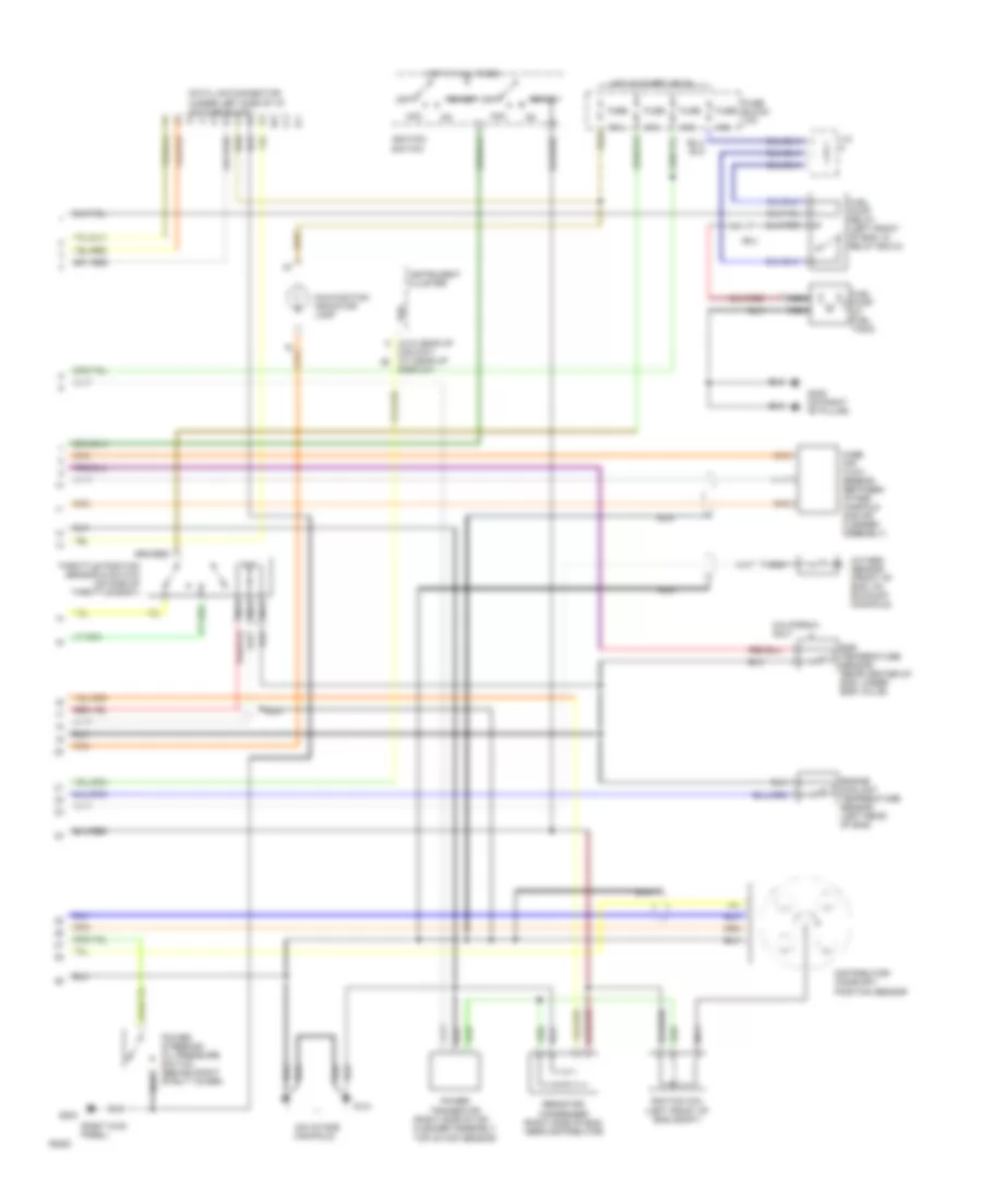
Engine Performance Wiring Diagrams (1 of 2) for Nissan Altima SE 1994

List of elements for Engine Performance Wiring Diagrams (1 of 2) for Nissan Altima SE 1994:
- (right rear of eng)
- (tach)
- 10a
- 25a
- A/t
- A/t control unit (in left kick panel)
- A/t only
- Air conditioning relay (right fender, in relay box-1)
- Air conditioning system
- Air conditioning system (a/c compressor)
- California only
- Cooling fans system
- Ecm relay (under center console, next to ecm)
- Egr & canister control solenoid valve (rear center of left side of egr valve)
- Engine control module (under center console)
- Fuel injectors
- Fuse
- Fusible link & fuse box (left front of eng compt)
- G101 (right front fender)
- Hot at all times
- Iacv- aac valve
- Iacv- ficd solenoid valve
- Inhibitor relay (left front of eng, in relay box-2)
- Instrument clusters system
- J/c
- Knock sensor (attached to top center of cylinder head)
- M/t
- Nca
- Neutral position switch (right side of tran- smission)
- No.1
- No.2
- No.3
- No.4
- Rear window defogger relay
- Transmissions system (inhibitor switch & relay)
Engine Performance Wiring Diagrams (2 of 2) for Nissan Altima SE 1994
List of elements for Engine Performance Wiring Diagrams (2 of 2) for Nissan Altima SE 1994:
- (on intake manifold)
- (right kick panel)
- (right side of air cleaner assembly, top of maf sensor)
- (w/o head-up
- 10a
- 15a
- Acc
- California only
- Data link connector (under left side of i/p, on fuse block)
- Dislpay) (w/ head-up
- Display)
- Distributor/ camshaft position sensor
- Egr temperature sensor (rear center of eng, under egr valve)
- Engine coolant temperature sensor (left rear of eng)
- Fuel pump (in fuel tank)
- Fuel pump relay (left front of eng, in relay box-2)
- Fuse
- Fuse block (i/p)
- G131
- G203
- G305 (on right "b" pillar)
- Hot at all times
- Hot in start or on
- Ignition coil (left front of eng compt)
- Ignition switch
- Instrument cluster
- J/c
- Malfunction indicator lamp
- Mass air flow sensor (between intake manifold and air cleaner assembly)
- Nca
- Off
- Oxygen sensor (front of eng, on exhaust manifold)
- Power steering/ oil pressure switch (behind right strut tower)
- Power transistor
- Resistor/ condenser (right side of eng, near distributor)
- Smj
- Start
- Throttle position sensor & switch (on side of throttle body)
- Vss