ENGINE PERFORMANCE
2.5L
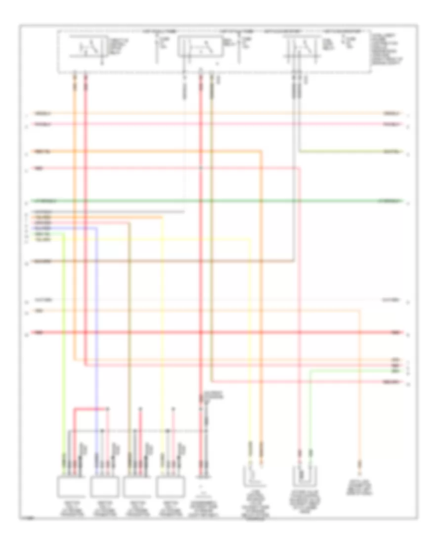
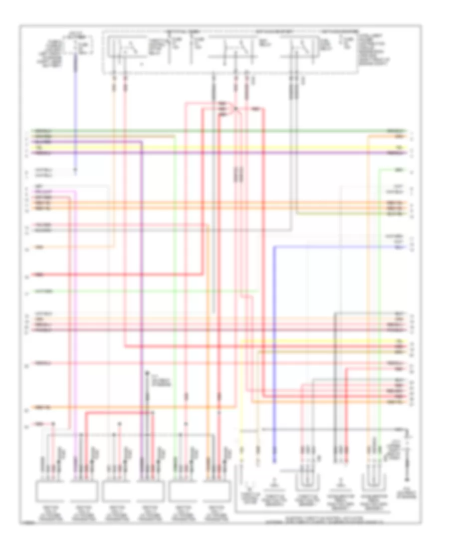
2.5L, Engine Performance Wiring Diagram (1 of 4) for Nissan Altima SL 2003

List of elements for 2.5L, Engine Performance Wiring Diagram (1 of 4) for Nissan Altima SL 2003:
- (on intake manifold) f16
- 15p
- A/t
- Anti-theft system
- Ascd brake switch (above brake pedal, on bracket)
- Ascd clutch switch (above clutch pedal, on bracket)
- Bncsw
- Brksw
- Can-h
- Can-l
- Cdcv
- Computer data lines system
- Crtn
- Cvbv
- Engine control module (behind glove box)
- Evap
- Evap canister purge volume control solenoid valve (on intake manifold, near throttle body)
- Evap canister vent control valve (below center of vehicle, on evap canister)
- Fpr sol
- Fuse 10a
- Fuse block (j/b) (left end of dash)
- Hot at all times
- Hot in on or start
- Hot in start
- Ign 1
- Ign 2
- Ign 3
- Ign 4
- Ignsw
- Immob
- Intelligent power distribution module engine room (ipdm e/r) (right front of engine compt)
- J/c 2 (behind upper left side of dash)
- Kline
- Led
- M/t
- Neut
- O2hfr
- O2hrr
- Park/neutral position switch (left rear of transaxle)
- Park/neutral position switch (on right rear of transaxle)
- Power steering oil pressure switch (on power steering pump)
- Pwst
- Red
- Ssoff
- Stoplight switch (above brake pedal, on bracket)
- Stsw
- Tacho
- Vacuum cut valve bypass valve (below center of vehicle, near evap canister)
- Vias
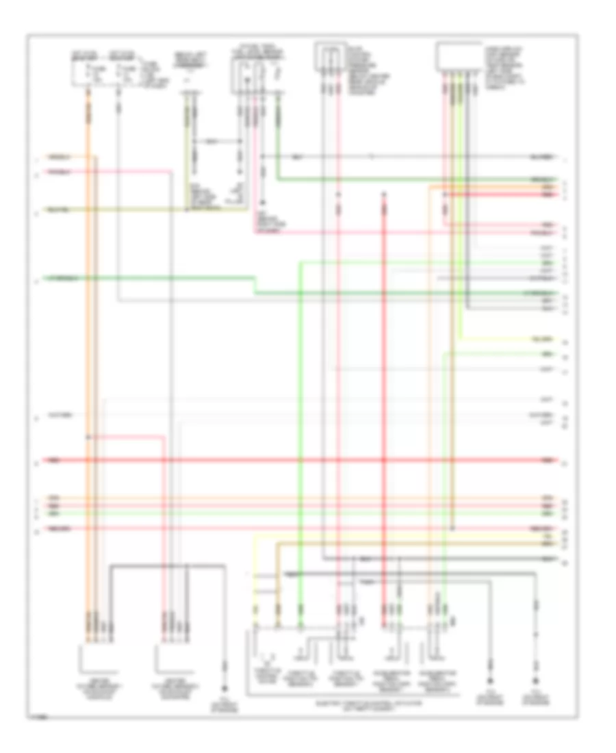
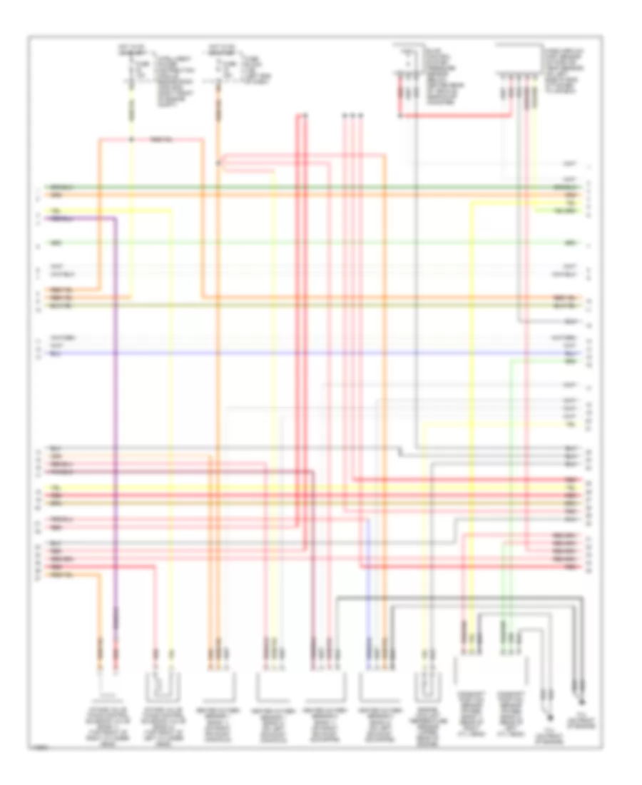
2.5L, Engine Performance Wiring Diagram (2 of 4) for Nissan Altima SL 2003
List of elements for 2.5L, Engine Performance Wiring Diagram (2 of 4) for Nissan Altima SL 2003:
- (on front of engine) f16
- Condenser 2 (on right side of engine comptartment)
- Data link connector (below left side of dash)
- E122
- E124
- Ecm relay
- Fuel pump relay
- Fuse 15a
- Hot at all times
- Hot in on or start
- Ignition coil 1 (w/ power transistor)
- Ignition coil 2 (w/ power transistor)
- Ignition coil 3 (w/ power transistor)
- Ignition coil 4 (w/ power transistor)
- Intake valve timing control solenoid valve (on right front of cylinder head)
- Intelligent power distribution module engine room (ipdm e/r) (right front of engine compt)
- Nca
- Plug spark
- Red
- Spark plug
- Throttle control motor relay
- Vias control solenoid valve (on right side of engine, below intake manifold)
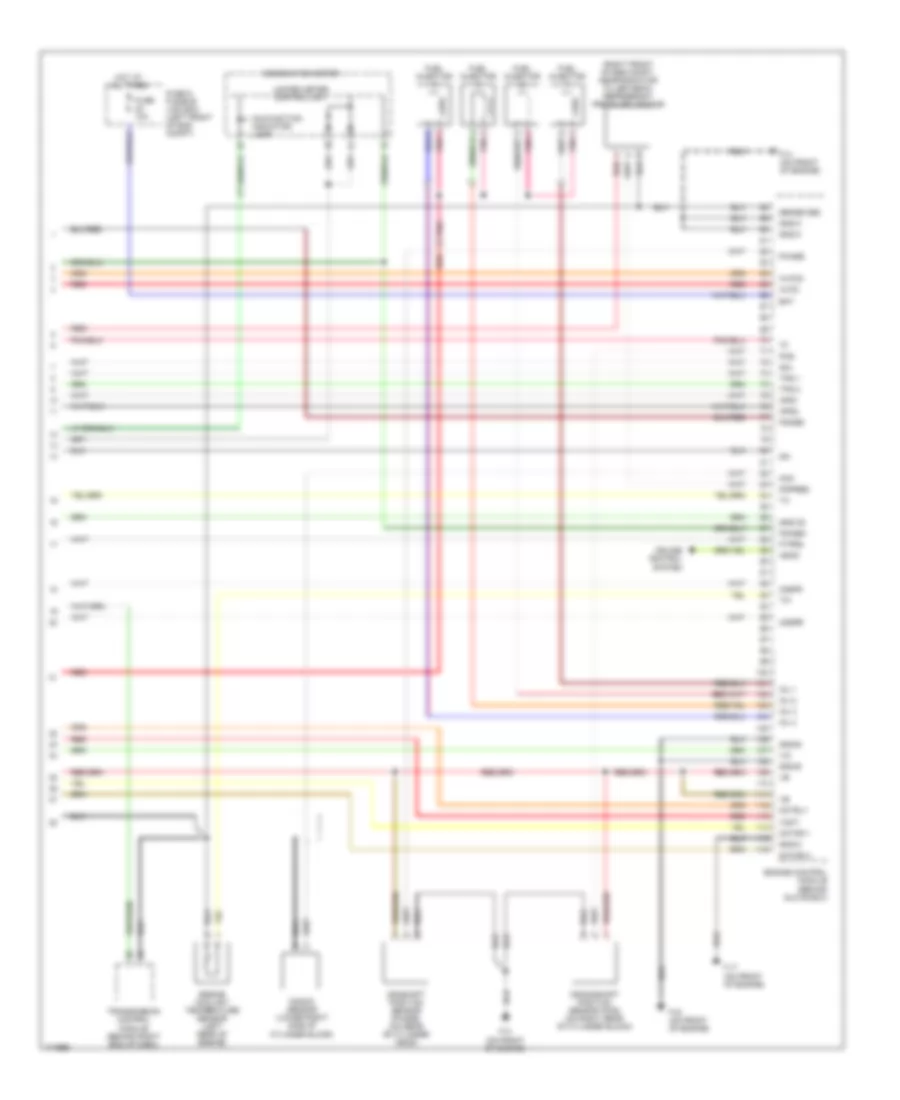
2.5L, Engine Performance Wiring Diagram (3 of 4) for Nissan Altima SL 2003
List of elements for 2.5L, Engine Performance Wiring Diagram (3 of 4) for Nissan Altima SL 2003:
- (below left rear seat) condenser 1
- (in fuel tank) fuel level sensor unit & fuel pump
- Accelerator pedal position (app) sensor 1
- Accelerator pedal position (app) sensor 2
- B19 (behind left side of rear seat back)
- B7 (left "b" pillar)
- Electric throttle control actuator (on throttle body)
- Evap control system pressure sensor (below center rear vehicle, near evap canister)
- F14 (on front of engine)
- F50
- Fuse 10a
- Fuse 15a
- Fuse block (j/b) (left end of dash)
- Heated oxygen sensor 1 (on exhaust manifold)
- Heated oxygen sensor 2 (on exhaust downpipe)
- Hot in on or start
- M40
- M57 (behind right side of dash)
- Mass airflow (maf) sensor (intake air temp sensor) (left side of eng compt, attatched to airbox)
- Nca
- Red
- Throttle control motor
- Throttle position (tp) sensor 1
- Throttle position (tp) sensor 2
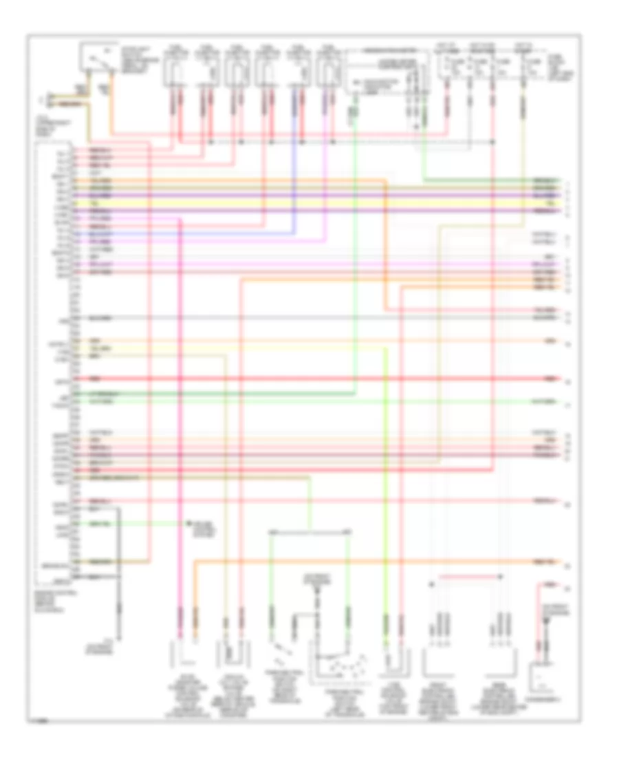
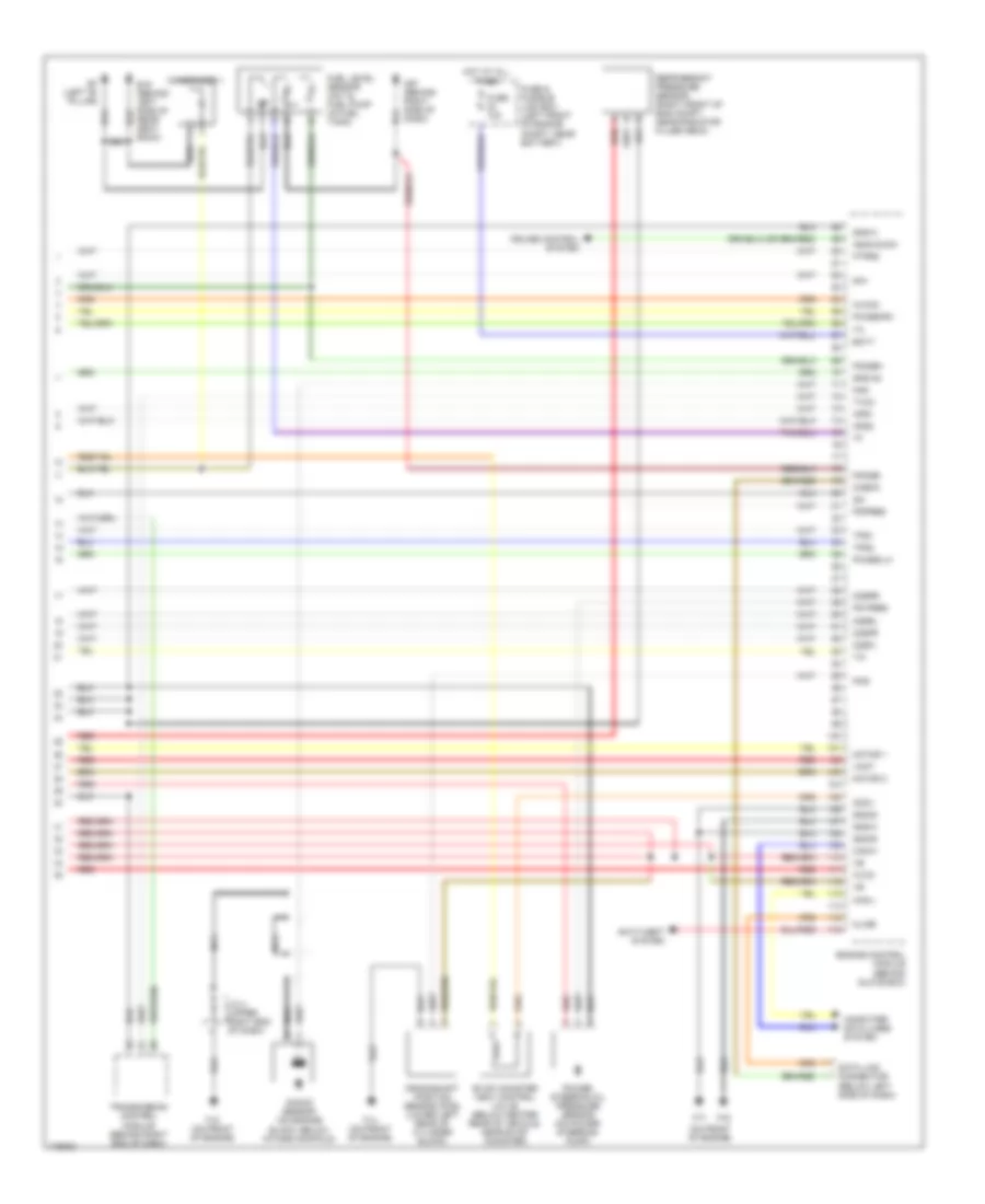
2.5L, Engine Performance Wiring Diagram (4 of 4) for Nissan Altima SL 2003
List of elements for 2.5L, Engine Performance Wiring Diagram (4 of 4) for Nissan Altima SL 2003:
- (right front of eng compt, near radiator filler neck) refrigerant pressure sensor
- Aps1
- Aps2
- Ascd
- Avcc
- Avcc2
- Bat
- Camshaft position sensor (phase) (on rear of cylinder head)
- Combination meter
- Crankshaft position sensor (pos) (on right rear of cylinder block)
- Cruise control system
- Engine control module (behind glove box)
- Engine coolant temperature sensor (left rear of engine)
- F14 (on front of engine)
- F16 (on front of engine)
- F17 (on front of engine)
- Fgage+
- Fgage-
- Ftprs
- Fuel injector
- Fuse & fusible link box (left front of eng compt)
- Fuse 10a
- Gnd-a2
- Gnd-c
- Gnd-e
- Gnd-m
- Hot at all times
- Inj 1
- Inj 2
- Inj 3
- Inj 4
- Ivc
- Knk
- Knock sensor (lower right side of cylinder block)
- Malfunction indicator lamp
- Motor 1
- Motor 2
- Motrly
- Nca
- O2sfr
- O2srr
- Pdpres
- Phase
- Pnk
- Pos
- Qa+
- Qa-
- Red
- Sense gnd
- Tps 1
- Tps 2
- Transmission control module (behind right end of dash)
- Unified meter control unit
- Vmot
3.5L
3.5L, Engine Performance Wiring Diagram (1 of 4) for Nissan Altima SL 2003
List of elements for 3.5L, Engine Performance Wiring Diagram (1 of 4) for Nissan Altima SL 2003:
- (on front of engine) f16
- (on front of engine) f17
- 15p
- A/t
- Ascd
- Brake sw
- Combination meter
- Condenser 2
- Crtn
- Cruise control system
- Cvbv
- Emnt1
- Emnt2
- Engine control module (behind glove box)
- Evap
- Evap canister purge volume control solenoid valve (on rear of intake manifold)
- F14 (on front of engine)
- Fpr
- Front electronic controlled engine mount (lower front center of eng compt)
- Fuel injector
- Fuse 10a
- Fuse block (j/b) (left end of dash)
- Gnd-c
- Hot at all times
- Hot in on or start
- Hot in start
- Ign 1
- Ign 2
- Ign 3
- Ign 4
- Ign 5
- Ign 6
- Ignsw
- Inj 1
- Inj 2
- Inj 3
- Inj 4
- Inj 5
- Inj 6
- Ivcb1
- Ivcb2
- J/c 2 (upper right side of dash)
- Led
- Load
- M/t
- Malfunction indicator lamp
- Motrly
- Neut
- O2hfl
- O2hfr
- O2hrl
- O2hrr
- Park/neutral position switch (left rear of transaxle)
- Park/neutral position switch (on right rear of transaxle)
- Rear electronic controlled engine mount (lower rear center of eng compt)
- Red
- Ssoff
- Stoplight switch (above brake pedal, on bracket)
- Stsw
- Tacho
- Unified meter control unit
- Vacuum cut valve bypass valve (below center rear of vehicle, near evap canister)
- Vias
- Vias control solenoid valve (top front of engine)
3.5L, Engine Performance Wiring Diagram (2 of 4) for Nissan Altima SL 2003
List of elements for 3.5L, Engine Performance Wiring Diagram (2 of 4) for Nissan Altima SL 2003:
- Accelerator pedal position (app) sensor 1
- Accelerator pedal position (app) sensor 2
- E122
- E124
- E40
- Ecm relay
- Electric throttle control actuator (integral with throttle body, on rear of intake manifold)
- F15 (on front of engine)
- F17 (on front of engine)
- F50
- Fuel pump relay
- Fuse & fusible link box (left front of engine compt, near battery)
- Fuse 10a
- Fuse 15a
- Hot at all times
- Hot in on or start
- Ignition coil 1 (w/ power transistor)
- Ignition coil 2 (w/ power transistor)
- Ignition coil 3 (w/ power transistor)
- Ignition coil 4 (w/ power transistor)
- Ignition coil 5 (w/ power transistor)
- Ignition coil 6 (w/ power transistor)
- Intelligent power distribution module engine room (ipdm e/r) (right front of engine compt)
- J/c 4 (upper right end of dash)
- Nca
- Plug spark
- Red
- Spark plug
- Throttle control motor
- Throttle control motor relay
- Throttle position (tp) sensor 1
- Throttle position (tp) sensor 2
3.5L, Engine Performance Wiring Diagram (3 of 4) for Nissan Altima SL 2003
List of elements for 3.5L, Engine Performance Wiring Diagram (3 of 4) for Nissan Altima SL 2003:
- Camshaft position sensor (phase) (bank 1) (rear of right cyl head)
- Camshaft position sensor (phase) (bank 2) (rear of left cyl head)
- Engine coolant temperature sensor (upper rear of engine)
- Evap control system pressure sensor (below center rear of vehicle, near evap canister)
- F14 (on front of engine)
- Fuse 10a
- Fuse 15a
- Fuse block (j/b) (left end of dash)
- Heated oxygen sensor 1 (bank 1) (on right exhaust manifold)
- Heated oxygen sensor 1 (bank 2) (on left exhaust manifold)
- Heated oxygen sensor 2 (bank 1) (on right exhaust downpipe)
- Heated oxygen sensor 2 (bank 2) (on left exhaust downpipe)
- Hot in on or start
- Intake valve timing control solenoid valve (bank 1) (top front of right cylinder head)
- Intake valve timing control solenoid valve (bank 2) (top front of left cylinder head)
- Intelligent power distribution module engine room (ipdm e/r) (right front of engine compt)
- Mass airflow (maf) sensor (intake air temp sensor) (on left side of eng, attached to air box)
- Red
3.5L, Engine Performance Wiring Diagram (4 of 4) for Nissan Altima SL 2003
List of elements for 3.5L, Engine Performance Wiring Diagram (4 of 4) for Nissan Altima SL 2003:
- (on front of engine)
- Anti-theft system
- Aps1
- Aps2
- Ascd b sw
- Avcc
- Avcc2
- B19 (behind left side of rear seat back)
- B7 (left "b" pillar)
- Batt
- Can-h
- Can-l
- Cdcv
- Check
- Computer data lines system
- Condenser 1
- Crankshaft position sensor (pos) (lower left rear of cylinder block)
- Cruise control system
- Data link connector (below left side of dash)
- Engine control module (behind glove box)
- Evap canister vent control valve (below center rear of vehicle, near evap canister)
- F14 (on front of engine)
- F15 (on front of engine)
- F16
- F17
- Fgage+
- Fgage-
- Ftprs
- Fuel level sensor unit & fuel pump (in fuel tank)
- Fuse & fusible link box (left front of engine compt, near battery)
- Fuse 10a
- Gnd-a
- Gnd-a2
- Gnd-e
- Gnd-m
- Hot at all times
- J/c 4 (upper right end of dash)
- Kline
- Knk
- Knock sensor (on engine block, below intake manifold)
- M57 (behind right side of dash)
- Motor 1
- Motor 2
- Nca
- O2sfl
- O2sfr
- O2srl
- O2srr
- Pdpres
- Phase-lh
- Phase-rh
- Pos
- Power steering oil pressure sensor (on power steering pump)
- Ps pres
- Qa+
- Qa-
- Red
- Refrigerant pressure sensor (right front of eng compt, near radiator filler neck)
- Tps1
- Tps2
- Transmission control module (behind right end of dash)
- Tvcc
- Vmot