ENGINE PERFORMANCE
5.6L
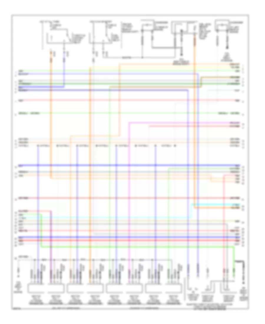
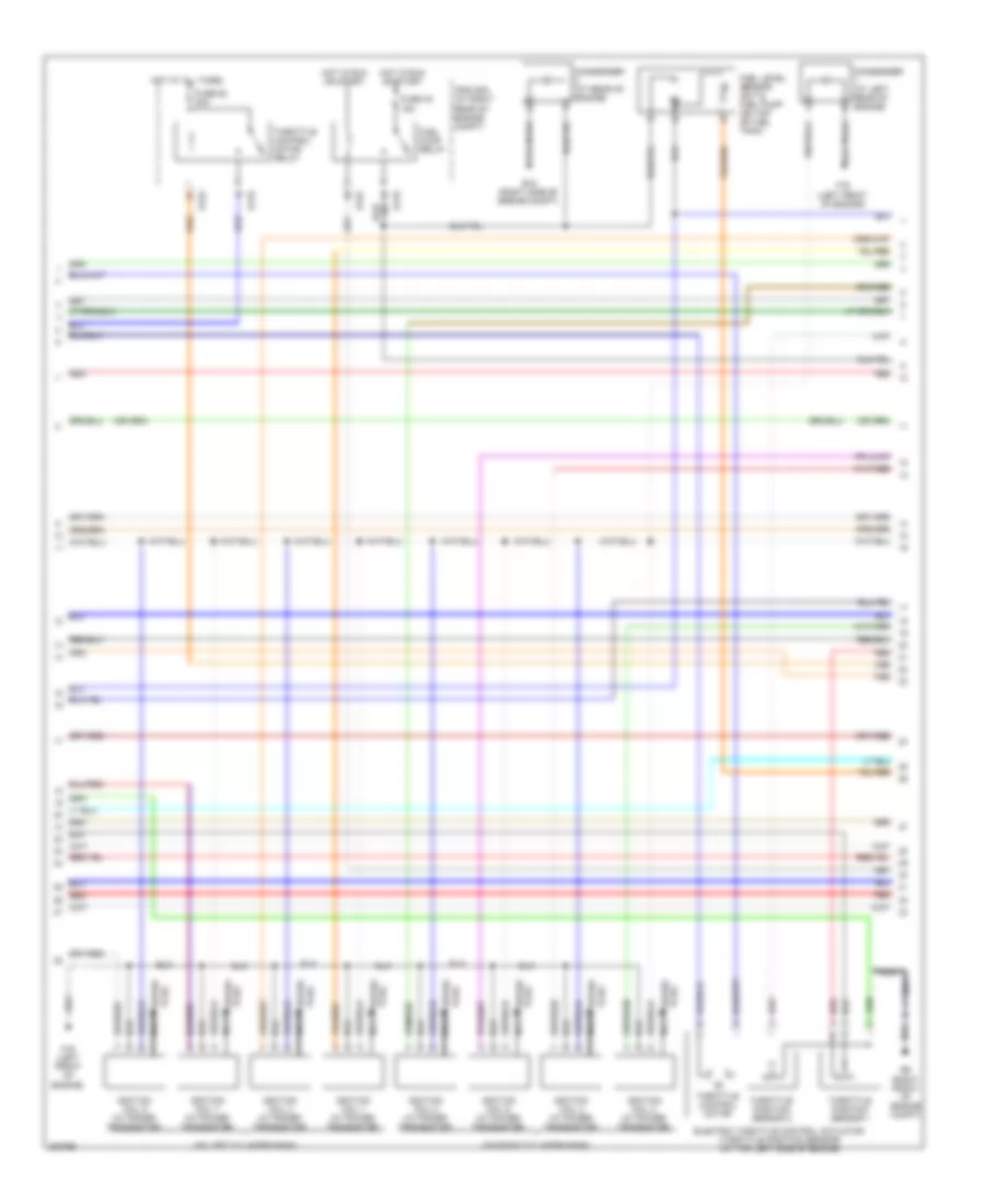
5.6L, Engine Performance Wiring Diagram (1 of 4) for Nissan Armada Titanium 2010

List of elements for 5.6L, Engine Performance Wiring Diagram (1 of 4) for Nissan Armada Titanium 2010:
- (on left cylinder bank)
- (on left cylinder bank) fuel injector 7
- (on right cylinder bank)
- (on right cylinder bank) fuel injector 8
- (right front of engine compt) e9
- A/f 1
- A/f h1
- A/f+1
- A/f+2
- Af h2
- Af-h2
- Avcc
- Avcc2
- C-vtc (l)
- C-vtc (r)
- Camshaft position sensor (phase) (at left rear of engine)
- Combination meter
- Computer data lines system
- Crankshaft position sensor (at left rear of engine)
- E119
- E9 (right front of engine compt)
- Ecm (at right side of engine compt)
- Evap
- Evap canister purge volume control solenoid valve (on left rear of engine)
- F54
- Ftprs
- Fuel injector
- Fuse 55 15a
- Gnd
- Hot in on or start
- Ign 5
- Ign 7
- Inj 1
- Inj 2
- Inj 3
- Inj 4
- Inj 5
- Inj 6
- Inj 7
- Intake valve timing control solenoid valve (bank 1) (top of engine assembly)
- Intake valve timing control solenoid valve (bank 2) (top of engine assembly)
- Ipdm e/r (at right rear of engine compt)
- Knk1
- Knk2
- Knock sensor (bank 1) (at top left side of engine)
- Knock sensor (bank 2) (at top of engine)
- M24
- M61 (behind center of dash)
- Malfunction indicator lamp
- Mtr 1
- Mtr 2
- O2hrl
- O2srl
- Oshrr
- Phase
- Pnk
- Pos
- Ps pres
- Qa+
- Red
- Tps 1
- Unified meter control unit (w/ information display)
- Vmot
- Vtc pus (r)
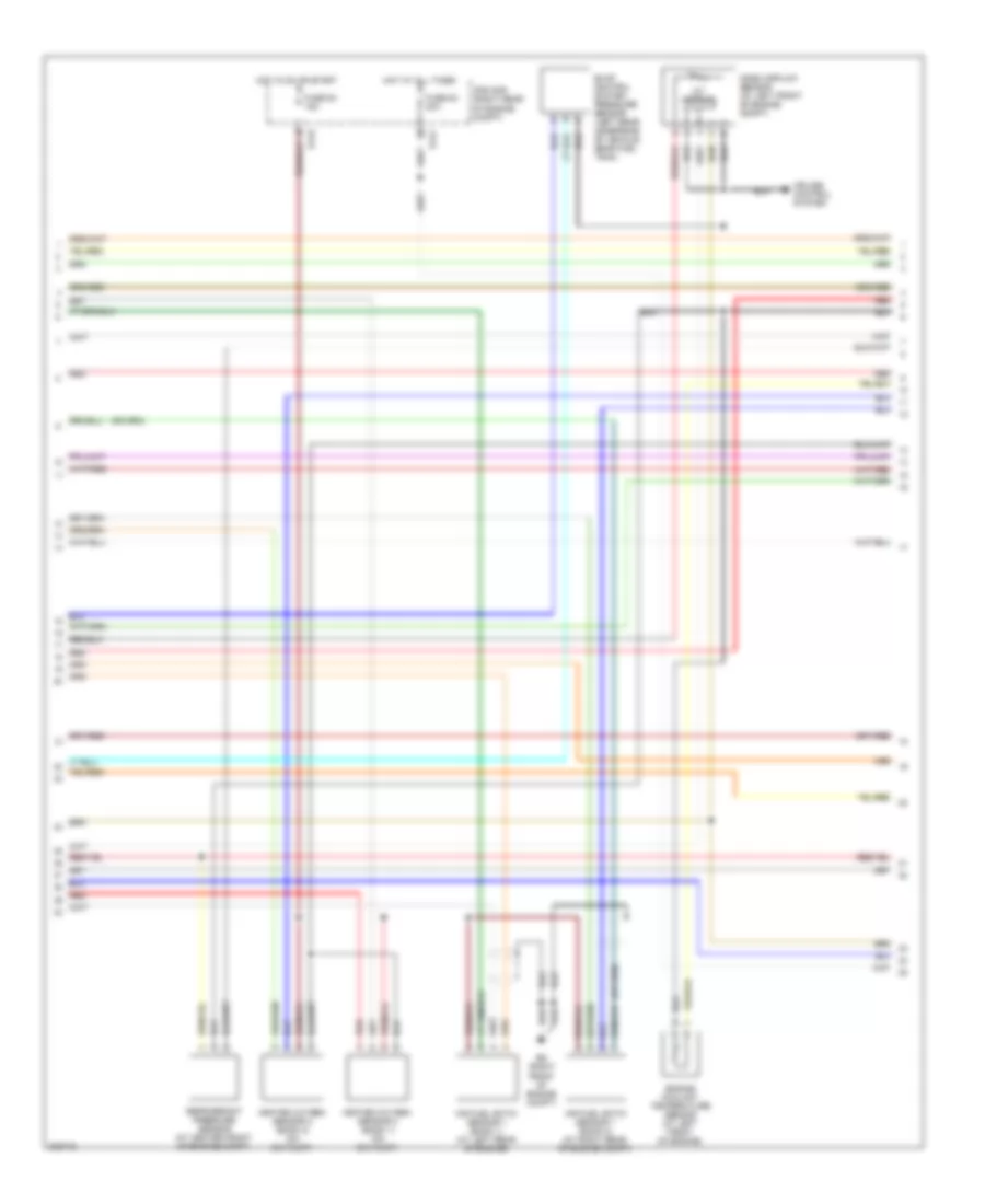
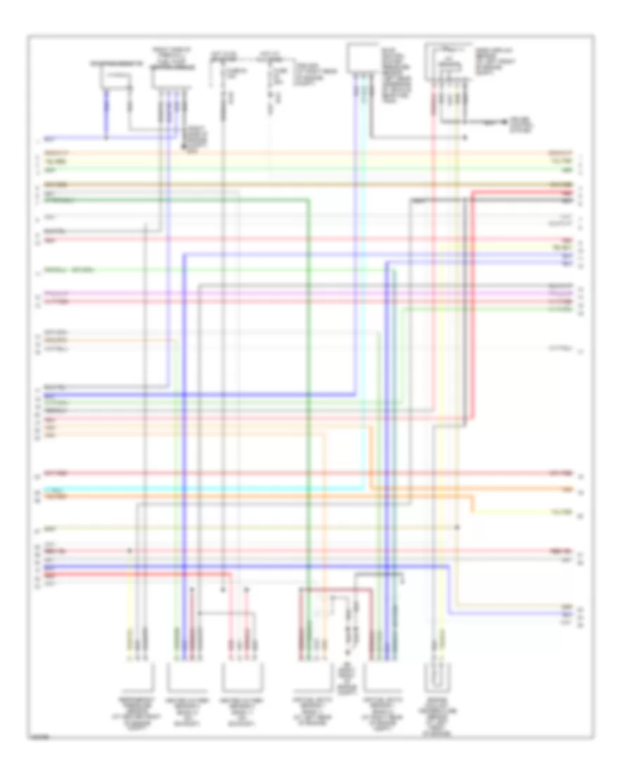
5.6L, Engine Performance Wiring Diagram (2 of 4) for Nissan Armada Titanium 2010
List of elements for 5.6L, Engine Performance Wiring Diagram (2 of 4) for Nissan Armada Titanium 2010:
- (on left cylinder bank)
- (on right cylinder bank)
- Condenser (at left rear of engine)
- Condenser (at rear of engine)
- E119
- E122
- E15 (right side of engine compt)
- E9 (right front of engine compt)
- Electric throttle control actuator (throttle position sensor) (at top left side of engine)
- F16 (left front of engine)
- Fuel level sensor unit & fuel pump (on top of fuel tank)
- Fuel pump relay
- Fuse 48 15a
- Fuse 52 20a
- Hot at all times
- Hot in on or start
- Ignition coil 1 (w/ power transistor)
- Ignition coil 2 (w/ power transistor)
- Ignition coil 3 (w/ power transistor)
- Ignition coil 4 (w/ power transistor)
- Ignition coil 5 (w/ power transistor)
- Ignition coil 6 (w/ power transistor)
- Ignition coil 7 (w/ power transistor)
- Ignition coil 8 (w/ power transistor)
- Ipdm e/r (at right rear of engine compt)
- Nca
- Plug spark
- Red
- Spark plug
- Throttle control motor
- Throttle control motor relay
- Throttle position sensor 1
- Throttle position sensor 2
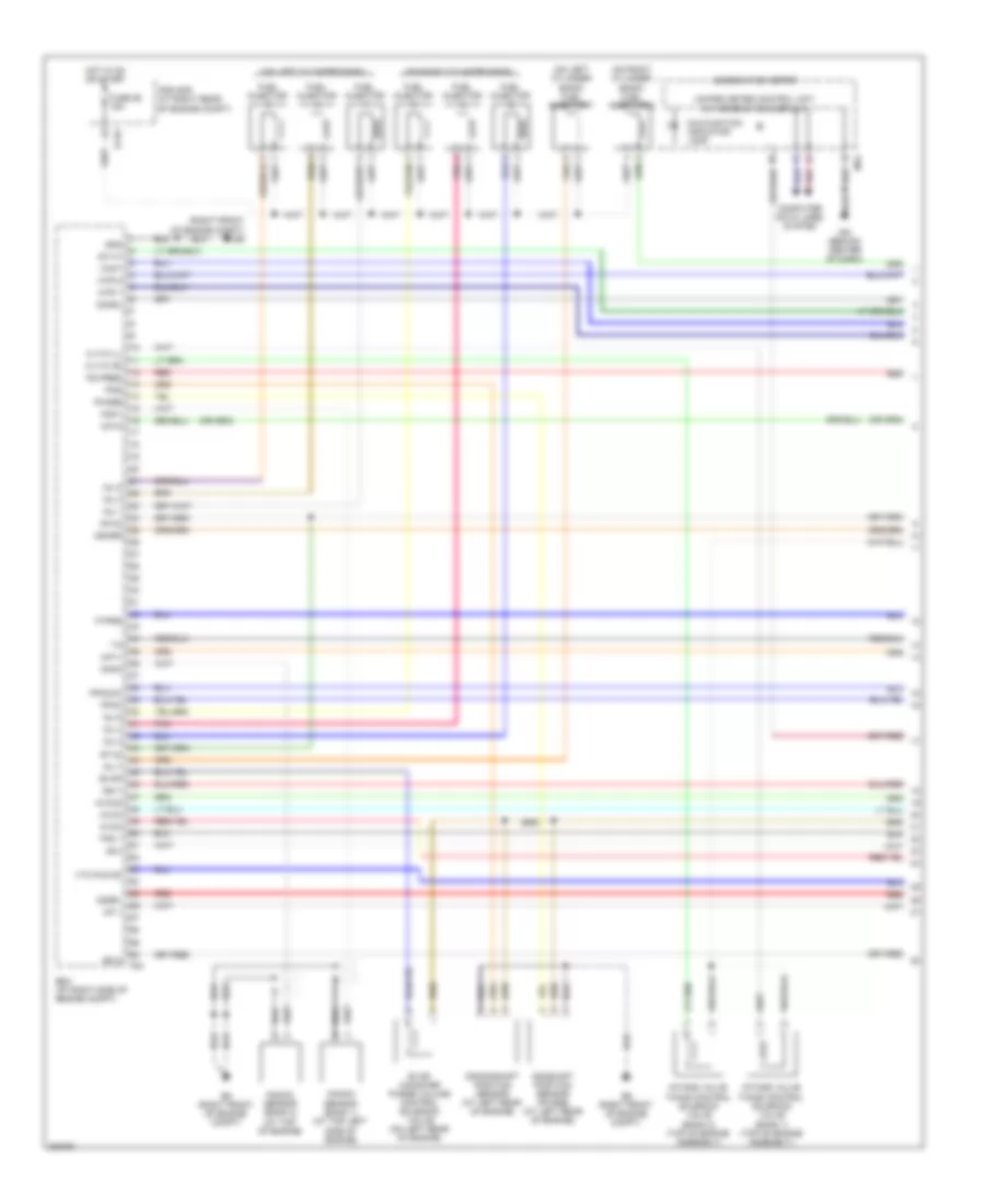
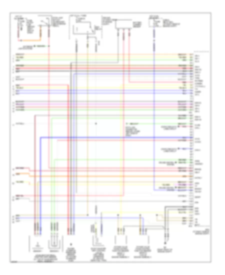
5.6L, Engine Performance Wiring Diagram (3 of 4) for Nissan Armada Titanium 2010
List of elements for 5.6L, Engine Performance Wiring Diagram (3 of 4) for Nissan Armada Titanium 2010:
- Air fuel ratio sensor 1 (bank 1) (at left rear of engine)
- Air fuel ratio sensor 1 (bank 2) (at right rear of engine compt)
- Cruise control system
- E119
- E121
- E9 (right front of engine compt)
- Engine coolant temperature sensor (at left front of engine)
- Evap control system pressure sensor (left rear underside of vehicle, near fuel tank)
- Fuse 53 20a
- Fuse 54 15a
- Heated oxygen sensor 2 (bank 1) (on exhaust)
- Heated oxygen sensor 2 (bank 2) (on exhaust)
- Hot at all times
- Hot in on or start
- Iat sensor
- Ipdm e/r (right rear of engine compt)
- Mass airflow sensor (at left front of engine compt)
- Red
- Refrigerant pressure sensor (at center front of engine compt)
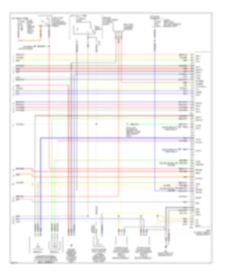
5.6L, Engine Performance Wiring Diagram (4 of 4) for Nissan Armada Titanium 2010
List of elements for 5.6L, Engine Performance Wiring Diagram (4 of 4) for Nissan Armada Titanium 2010:
- A/f 2
- Accelerator pedal position (app) sensor (at top of accelerator pedal assembly)
- Aps1
- Aps2
- Ascdsw
- Avcc
- Avcc2
- Batt
- Battery current sensor
- Bncsw
- Brake
- Can h
- Can l
- Cdcv
- Computer data lines circuit
- Cruise control system
- Cursen
- Data link connector (behind lower left side of dash)
- E119
- E16
- E9 (right front of engine compt)
- Ecm (at right side of engine compt)
- Ecm relay
- Evap canister vent control valve (left rear underside of vehicle, near fuel tank)
- Exterior lights system
- F54
- Fpr
- Fuse & relay box (at right rear of engine compt)
- Fuse 10a
- Fuse 53 20a
- Fuse block (j/b) (behind right end of dash)
- Gnd
- Gnd 02
- Gnd a
- Gnd a2
- Hot at all times
- Hot in on or start
- Ign 1
- Ign 2
- Ign 3
- Ign 4
- Ign 6
- Ign 8
- Ign sw
- Inj 8
- Intake valve timing control position sensor (bank 1) (top of engine assembly)
- Intake valve timing control position sensor (bank 2) (top of engine assembly)
- Ipdm e/r (at right rear of engine compt)
- Kline
- M60
- Motrly
- Neut
- O2srr
- Pd pres
- Pnk
- Power steering pressure sensor (at power steering pump)
- Red
- Sensor 1
- Sensor 2
- Ssoff
- Stop lamp switch (on bracket, above brake pedal)
- Tps2
- Vtc pus (l)
5.6L FLEX FUEL
5.6L Flex Fuel, Engine Performance Wiring Diagram (1 of 4) for Nissan Armada Titanium 2010
List of elements for 5.6L Flex Fuel, Engine Performance Wiring Diagram (1 of 4) for Nissan Armada Titanium 2010:
- (on left cylinder bank)
- (on left cylinder bank) fuel injector 7
- (on right cylinder bank)
- (on right cylinder bank) fuel injector 8
- (right front of engine compt) e9
- A/f 1
- A/f h1
- A/f+1
- A/f+2
- Af h2
- Af-h2
- Avcc
- Avcc2
- C-vtc (l)
- C-vtc (r)
- Camshaft position sensor (phase) (at left rear of engine)
- Combination meter
- Computer data lines system
- Crankshaft position sensor (at left rear of engine)
- E119
- E9 (right front of engine compt)
- Ecm (at right side of engine compt)
- Evap
- Evap canister purge volume control solenoid valve (on left rear of engine)
- F54
- Fpcm
- Fpcmck
- Ftprs
- Fuel injector
- Fuse 55 15a
- Gnd
- Hot in on or start
- Ign 5
- Ign 7
- Inj 1
- Inj 2
- Inj 3
- Inj 4
- Inj 5
- Inj 6
- Inj 7
- Intake valve timing control solenoid valve (bank 1) (top of engine assembly)
- Intake valve timing control solenoid valve (bank 2) (top of engine assembly)
- Ipdm e/r (at right rear of engine compt)
- Knk1
- Knk2
- Knock sensor (bank 1) (at top left side of engine)
- Knock sensor (bank 2) (at top of engine)
- M24
- M61 (behind center of dash)
- Malfunction indicator lamp
- Mtr 1
- Mtr 2
- O2hrl
- O2srl
- Oshrr
- Phase
- Pnk
- Pos
- Ps pres
- Qa+
- Red
- Tps 1
- Unified meter control unit (w/ information display)
- Vmot
- Vtc pus (r)
5.6L Flex Fuel, Engine Performance Wiring Diagram (2 of 4) for Nissan Armada Titanium 2010
List of elements for 5.6L Flex Fuel, Engine Performance Wiring Diagram (2 of 4) for Nissan Armada Titanium 2010:
- (on left cylinder bank)
- (on right cylinder bank)
- Condenser (at left rear of engine)
- Condenser (at rear of engine)
- E119
- E122
- E15 (right side of engine compt)
- E9 (right front of engine compt)
- Electric throttle control actuator (throttle position sensor) (at top left side of engine)
- F16 (left front of engine)
- Fuel level sensor unit & fuel pump (on top of fuel tank)
- Fuel pump relay
- Fuse 48 15a
- Fuse 52 20a
- Hot at all times
- Hot in run or start
- Ignition coil 1 (w/ power transistor)
- Ignition coil 2 (w/ power transistor)
- Ignition coil 3 (w/ power transistor)
- Ignition coil 4 (w/ power transistor)
- Ignition coil 5 (w/ power transistor)
- Ignition coil 6 (w/ power transistor)
- Ignition coil 7 (w/ power transistor)
- Ignition coil 8 (w/ power transistor)
- Ipdm e/r (at right rear of engine compt)
- Nca
- Plug spark
- Red
- Spark plug
- Throttle control motor
- Throttle control motor relay
- Throttle position sensor 1
- Throttle position sensor 2
5.6L Flex Fuel, Engine Performance Wiring Diagram (3 of 4) for Nissan Armada Titanium 2010
List of elements for 5.6L Flex Fuel, Engine Performance Wiring Diagram (3 of 4) for Nissan Armada Titanium 2010:
- (right side of firewall) fuel pump control module
- Air fuel ratio sensor 1 (bank 1) (at left rear of engine)
- Air fuel ratio sensor 1 (bank 2) (at right rear of engine compt)
- Cruise control system
- Dropping resistor
- E119
- E121
- E9 (right front of engine compt)
- Engine compt) e15
- Engine coolant temperature sensor (at left front of engine)
- Evap control system pressure sensor (left rear underside of vehicle, near fuel tank)
- Fuse 20a
- Fuse 54 15a
- Heated oxygen sensor 2 (bank 1) (on exhaust)
- Heated oxygen sensor 2 (bank 2) (on exhaust)
- Hot at all times
- Hot in on or start
- Iat sensor
- Ipdm e/r (at right rear of engine compt)
- Mass airflow sensor (at left front of engine compt)
- Red
- Refrigerant pressure sensor (at center front of engine compt)
5.6L Flex Fuel, Engine Performance Wiring Diagram (4 of 4) for Nissan Armada Titanium 2010
List of elements for 5.6L Flex Fuel, Engine Performance Wiring Diagram (4 of 4) for Nissan Armada Titanium 2010:
- A/f 2
- Accelerator pedal position (app) sensor (at top of accelerator pedal assembly)
- Aps1
- Aps2
- Ascdsw
- Avcc
- Avcc2
- Batt
- Battery current sensor
- Bncsw
- Brake
- Can h
- Can l
- Cdcv
- Computer data lines circuit
- Cruise control system
- Cursen
- Data link connector (behind lower left side of dash)
- E119
- E16
- E9 (right front of engine compt)
- Ecm (at right side of engine compt)
- Ecm relay
- Evap canister vent control valve (left rear underside of vehicle, near fuel tank)
- Exterior lights system
- F54
- Fpr
- Fuse & relay box (at right rear of engine compt)
- Fuse 10a
- Fuse 53 20a
- Fuse block (j/b) (behind right end of dash)
- Gnd
- Gnd 02
- Gnd a
- Gnd a2
- Hot at all times
- Hot in on or start
- Ign 1
- Ign 2
- Ign 3
- Ign 4
- Ign 6
- Ign 8
- Ign sw
- Inj 8
- Intake valve timing control position sensor (bank 1) (top of engine assembly)
- Intake valve timing control position sensor (bank 2) (top of engine assembly)
- Ipdm e/r (at right rear of engine compt)
- Kline
- M60
- Motrly
- Neut
- O2srr
- Pd pres
- Pnk
- Power steering pressure sensor (at power steering pump)
- Red
- Sensor 1
- Sensor 2
- Ssoff
- Stop lamp switch (on bracket, above brake pedal)
- Tps2
- Vtc pus (l)