ENGINE PERFORMANCE
3.8L TURBO
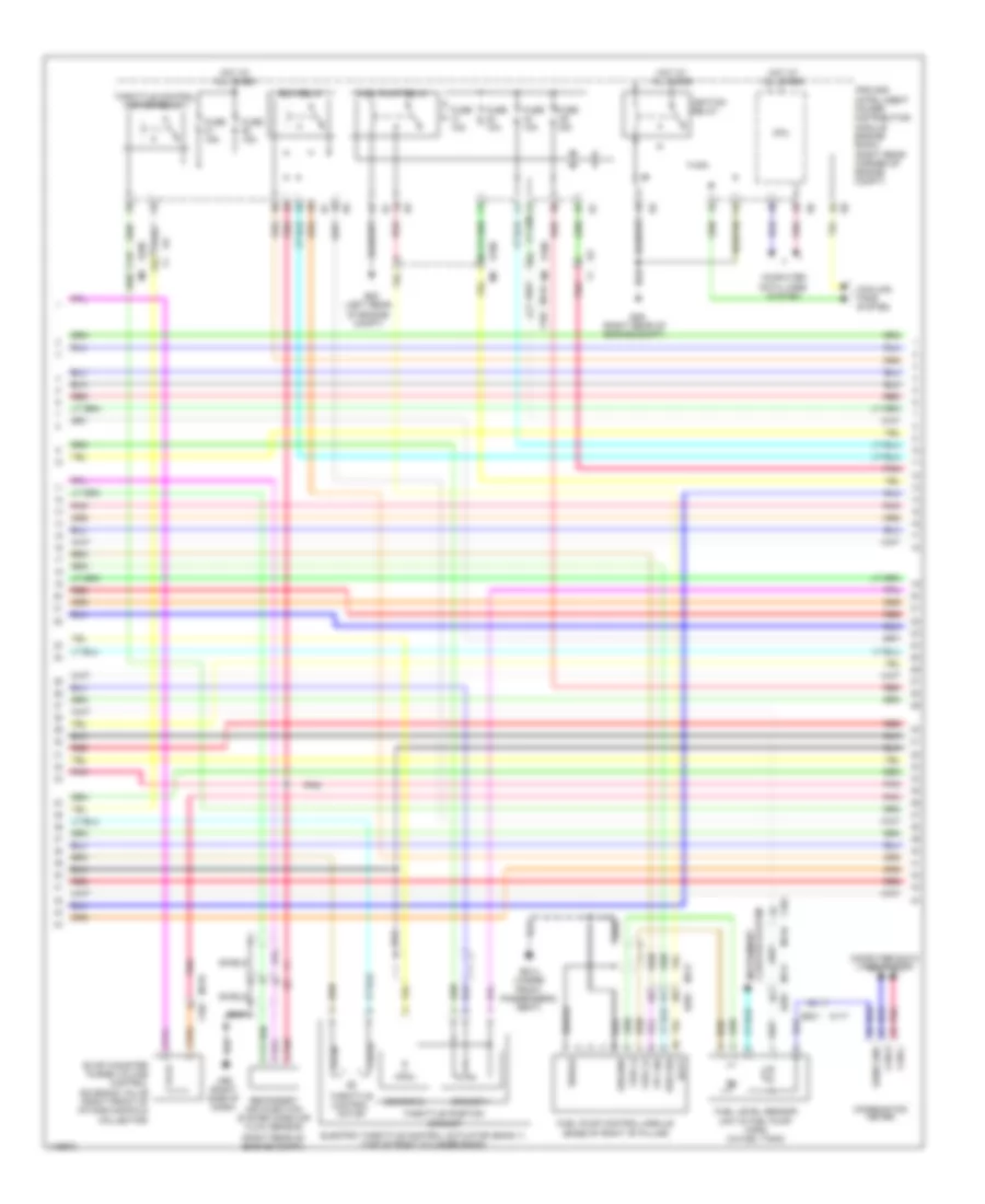
3.8L Turbo, Engine Performance Wiring Diagram (1 of 5) for Nissan GT-R Premium 2014

List of elements for 3.8L Turbo, Engine Performance Wiring Diagram (1 of 5) for Nissan GT-R Premium 2014:
- (ignition coils 1, 3 & 5: top of right cylinder bank) (ignition coils 2, 4 & 6: top of left cylinder bank)
- (rear of right cylinder bank)
- Af-h1(denso)
- Af-h2(denso)
- Avcc
- Bat curnt sens
- Camshaft position sensor (phase) (bank 1)
- Cdcv
- Cruise control system
- Cvtc 1
- Cvtc 2
- E106
- Ecm (engine control module) (right end of dash)
- Evap
- F101
- F102
- F103
- F103 m116
- F50 (center rear of engine)
- Fpc
- Fpcck
- Gnd
- Gnd-saafm/tam
- Gnda-phase 1
- Gnda-qa1/ta1
- Gnda-qa2/ta2
- Gnda-tps1-b1
- Gnda-tps1-b2
- Gnda-tw/to/tf
- Ign 1
- Ign 2
- Ign 3
- Ign-i 4
- Ign-i 5
- Ign-i 6
- Ignition coil 1 (w/ power transistor)
- Ignition coil 2 (w/ power transistor)
- Ignition coil 3 (w/ power transistor)
- Ignition coil 4 (w/ power transistor)
- Ignition coil 5 (w/ power transistor)
- Ignition coil 6 (w/ power transistor)
- Inj 1 (115v)
- Inj 2 (115v)
- Inj 3 (115v)
- Inj 4 (115v)
- Inj 5 (115v)
- Inj 6 (115v)
- Intake air temperature sensor
- M116
- M95 (right side of dash)
- Manifold absolute pressure sensor (right rear of intake manifold)
- Mass air flow sensor (bank 1) (in right bank air intake duct)
- Mass air flow sensor (bank 2) (in left bank air intake duct)
- Motor1-b1
- Motor1-b2
- Motor2(l)
- Motor2-b1
- Nca
- O2hr1
- Out put
- Phase 1
- Pnk
- Power steering pressure sensor (on power steering pump)
- Qa1+
- Qa2+
- Red
- Refrigerant pressure sensor (right front of engine compt)
- Saafm
- Spark plug
- Ta1
- Tpres 3
- Tps1-b1
- Tps1-b2
- Tps2-b1
- Tps2-b2
- Vmot-b1
- Vmot-b2
- Wgc
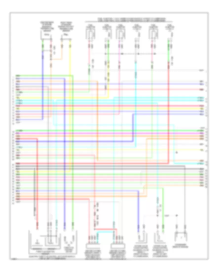
3.8L Turbo, Engine Performance Wiring Diagram (2 of 5) for Nissan GT-R Premium 2014
List of elements for 3.8L Turbo, Engine Performance Wiring Diagram (2 of 5) for Nissan GT-R Premium 2014:
- (left rear of engine compt)
- (right rear of engine compt)
- B201
- B214 (under front passenger's seat)
- Batt
- Can-h
- Can-l
- Close
- Cluster system instrument
- Combination meter
- Computer data lines system
- Cooling fans system
- Cpu
- Diag sig
- E106
- E106 m6
- E20
- E3 f1
- E46
- Ecm relay
- Electric throttle control actuator (bank 1) (top of right cylinder bank)
- Evap canister purge volume control solenoid valve (right front of intake manifold collector)
- F1 e3
- F103
- Fpc sig
- Fuel (+)
- Fuel (-)
- Fuel level sensor unit & fuel pump (main) (in fuel tank)
- Fuel pump control module (base of right "b" pillar)
- Fuel pump relay
- Fuse 10a
- Fuse 15a
- Ground
- Hot at all times
- Ignition relay
- Ipdm e/r (intelligent power distribution module engine room) (right rear corner of engine compt)
- M116
- M116 f103
- M117
- M117 b201
- M95 (right side of dash)
- Open
- Pnk
- Red
- Secondary air injection system mass air flow sensor
- Sens gnd
- Sensor 1
- Sensor 2
- Sheild
- Shield
- Throttle control motor
- Throttle control motor relay
- Throttle position sensor
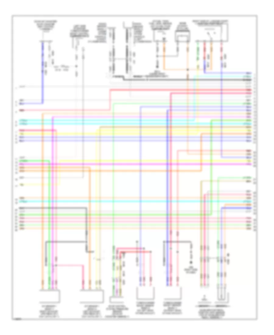
3.8L Turbo, Engine Performance Wiring Diagram (3 of 5) for Nissan GT-R Premium 2014
List of elements for 3.8L Turbo, Engine Performance Wiring Diagram (3 of 5) for Nissan GT-R Premium 2014:
- (center rear of engine) engine oil temperature sensor
- (fuel injector 1, 3 & 5: under intake manifold, in right cylinder bank) (fuel injector 2, 4 & 6: under intake manifold, in left cylinder bank)
- (right rear of engine) engine coolant temperature sensor
- Close
- Condenser (rear of engine)
- E106
- Electric throttle control actuator (bank 2) (top of left cylinder bank)
- F120 f48
- F201 f47
- Fuel injector
- Heated oxygen sensor 2 (bank 1) (right exhaust, upstream of 3 way catalyst 2)
- Heated oxygen sensor 2 (bank 2) (left exhaust, upstream of 3 way catalyst 2)
- Intake valve timing control solenoid valve (bank 1) (front of right cylinder bank)
- Intake valve timing control solenoid valve (bank 2) (front of left cylinder bank)
- M116 f103
- Open
- Pnk
- Red
- Sensor 1
- Sensor 2
- Throttle control motor
- Throttle position sensor
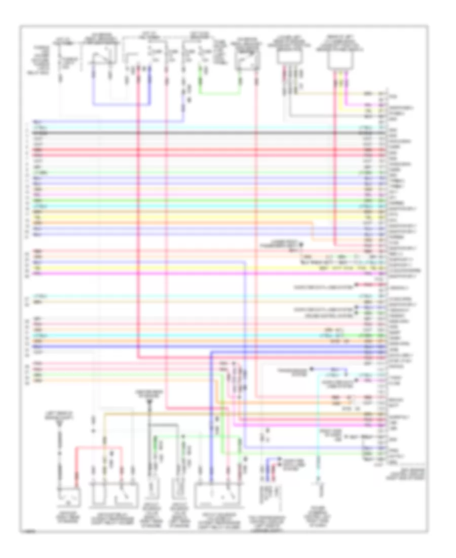
3.8L Turbo, Engine Performance Wiring Diagram (4 of 5) for Nissan GT-R Premium 2014
List of elements for 3.8L Turbo, Engine Performance Wiring Diagram (4 of 5) for Nissan GT-R Premium 2014:
- (base of right "b" pillar) condenser
- (in fuel tank) fuel level sensor unit & fuel pump (sub fuel pump)
- (left side of engine) turbocharger boost control solenoid valve
- (on evap canister) evap canister vent control valve
- (right side of luggage compt) sub fuel pump relay
- A/f sensor 1 (bank 1) (right exhaust, upstream of 3 way catalyst 1)
- A/f sensor 1 (bank 2) (left exhaust, upstream of 3 way catalyst 1)
- Accelerator pedal position (app) sensor (top of accelerator pedal assembly)
- B201
- B201 m117
- B214 (under front passenger's seat)
- E106
- Evap control system pressure sensor (on evap canister assembly)
- F103
- F201
- F47
- Knock sensor (bank 1) (under intake manifold, in right cylinder bank)
- Knock sensor (bank 2) (under intake manifold, in left cylinder bank)
- M116
- M117
- M95 (right side of dash)
- Pnk
- Red
- Sensor 1
- Sensor 2
- Shield
- Turbocharger boost sensor (bank 1) (on right bank intake air duct)
- Turbocharger boost sensor (bank 2) (on left bank intake air duct)
3.8L Turbo, Engine Performance Wiring Diagram (5 of 5) for Nissan GT-R Premium 2014
List of elements for 3.8L Turbo, Engine Performance Wiring Diagram (5 of 5) for Nissan GT-R Premium 2014:
- (center rear of engine) f49
- (left rear of engine compt) e20
- (lower left rear of engine) crankshaft position sensor (pos)
- (on brake pedal bracket) ascd brake switch
- (on brake pedal bracket) stop light switch
- (rear of left cylinder bank) camshaft position sensor (phase) (bank 2)
- (right side of dash) m95
- (under front passenger's seat) b214
- 02sr2
- 10f
- 15f
- Af+1
- Af+2
- Af-1
- Af-2
- Air cut solenoid valve (bank 1) (right rear of engine)
- Air cut solenoid valve (bank 2) (left rear of engine)
- Air cut solenoid valve relay (in right rear engine compt relay holder)
- Air pump (right rear of engine)
- Air pump relay (in right rear engine compt relay holder)
- Aps1
- Aps2
- Ascdsw
- Avcc
- Avcc2-aps2
- Avcc2-pd/pspre
- B201 m117
- Batt
- Bnc sw
- Can-h
- Can-l
- Computer data lines system
- Cruise control system
- E103
- E106
- E106 m6
- E203
- Ecm (engine control module) (right end of dash)
- F102
- F103
- F37
- Fpr2
- Fuse 10a
- Fuse 15a
- Fuse block (j/b) (left kick panel)
- Fusible link holder (on fuse/ fusible link & relay box)
- Fusible link k 40a
- Gnd
- Gnd-phase 2
- Gnda-aps1
- Gnda-aps2
- Hot at all times
- Hot in on or start
- Ignsw
- Kline
- Knk1(2gain)
- Knk2(2gain)
- M107
- M116
- M6 e106
- Mot rly
- O2sr1
- Pdpres
- Phase 2
- Pnk
- Pnp sig
- Pos
- Power steering control unit (right side of dash)
- Pspres
- Red
- Res 1,2
- Rly sig starter
- Sapmp rly
- Savalverly
- Shield
- Sns pwr sply
- Ssoff
- Stop lp sw
- Sub pump v+
- Sub pump v-
- Tacho
- Tcm (transmission control module) (left side of luggage compt)
- Tpres 1
- Tpres 2
- Transmissions system
- Vbr
- Vehcan-h1
- Vehcan-l1