ENGINE PERFORMANCE
3.5L
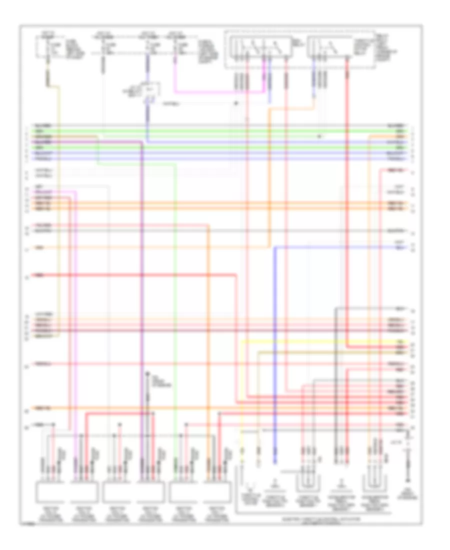
3.5L, Engine Performance Wiring Diagram (1 of 4) for Nissan Maxima GXE 2003

List of elements for 3.5L, Engine Performance Wiring Diagram (1 of 4) for Nissan Maxima GXE 2003:
- (front of engine) f40
- (front of engine) f41
- 11k
- A/c system
- A/c system (man a/c)
- A/t
- Acpdcut
- Acrly
- Arcon
- Brake sw
- Combination meter
- Condenser
- Cooling fans system
- Crtn
- Cruise control system
- Cruise lmp
- Ctrl sw
- Cvbv
- Emnt1
- Emnt2
- Engine control module (behind lower center of dash)
- Evap canister purge volume control solenoid valve (on rear side of intake manifold lower collector)
- Evap-nam
- F42 (front of engine)
- Fpr
- Front electronic controlled engine mount (left rear of engine)
- Fuel injector
- Fuse 10a
- Fuse 15a
- Fuse block (behind left side of dash)
- Gnd-c
- Headlights, defogger systems
- Hot at all times
- Hot in on or start
- Ign 1
- Ign 2
- Ign 3
- Ign 4
- Ign 5
- Ign 6
- Ignsw
- Inj 1
- Inj 2
- Inj 3
- Inj 4
- Inj 5
- Inj 6
- Ivcl
- Ivcr
- Led
- M/t
- Malfunction indicator lamp
- Motrly
- Neut
- O2hfl
- O2hfr
- O2hrl
- O2hrr
- Park/neutral position switch (left rear side of transaxle)
- Park/neutral position switch (on right rear side of transaxle case)
- R/def
- Rear electronic controlled engine mount (lower right rear of engine)
- Red
- Rfrh
- Rfrl
- Set lmp
- Ssoff
- Stoplight switch (on brake pedal bracket)
- Stsw
- Tacho
- Two
- Unified meter control unit
- Vacuum cut valve bypass valve (on evap purge line, between fuel tank & evap canister)
- Vias
- Vias control solenoid valve (top front of engine)
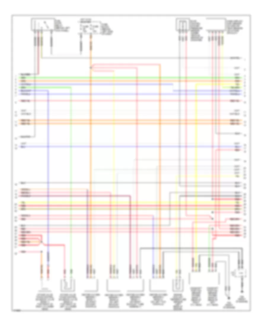
3.5L, Engine Performance Wiring Diagram (2 of 4) for Nissan Maxima GXE 2003
List of elements for 3.5L, Engine Performance Wiring Diagram (2 of 4) for Nissan Maxima GXE 2003:
- Accelerator pedal position (app) sensor 1
- Accelerator pedal position (app) sensor 2
- Ecm relay
- Electric throttle control actuator (on throttle body)
- F39 (front of engine)
- F40 (front of engine)
- F64
- Fuse & fusible link box (left side of engine compt)
- Fuse 10a
- Fuse 15a
- Fuse block (behind left side of dash)
- Hot at all times
- Hot in start
- Ignition coil 1 (w/ power transistor)
- Ignition coil 2 (w/ power transistor)
- Ignition coil 3 (w/ power transistor)
- Ignition coil 4 (w/ power transistor)
- Ignition coil 5 (w/ power transistor)
- Ignition coil 6 (w/ power transistor)
- J/c 12 (in relay box 1)
- J/c 19
- M159
- Nca
- Plug spark
- Red
- Relay box 2 (left front corner of engine compt)
- Spark plug
- Throttle control motor
- Throttle control motor relay
- Throttle position (tp) sensor 1
- Throttle position (tp) sensor 2
3.5L, Engine Performance Wiring Diagram (3 of 4) for Nissan Maxima GXE 2003
List of elements for 3.5L, Engine Performance Wiring Diagram (3 of 4) for Nissan Maxima GXE 2003:
- 13l
- Camshaft position sensor (phase) (bank 1) (rear of right cyl head)
- Camshaft position sensor (phase) (bank 2) (rear of left cyl head)
- Engine coolant temperature sensor (left rear of engine)
- Evap control system pressure sensor (under vehicle, near evap canister)
- F39 (front of engine)
- F42 (front of engine)
- Fuel pump relay (behind left kick panel)
- Fuse 15a
- Fuse block (behind left side of dash)
- Heated oxygen sensor 1 (bank 1) (on right exhaust manifold)
- Heated oxygen sensor 1 (bank 2) (on left exhaust manifold)
- Heated oxygen sensor 2 (bank 1) (on front exhaust tube assembly)
- Heated oxygen sensor 2 (bank 2) (on left twc manifold)
- Hot in on or start
- Intake valve timing control solenoid valve (bank 1) (top front of right cylinder head)
- Intake valve timing control solenoid valve (bank 2) (top front of left cylinder head)
- J/c
- Mass airflow (maf) sensor (intake air temp sensor) (on intake air duct)
- Red
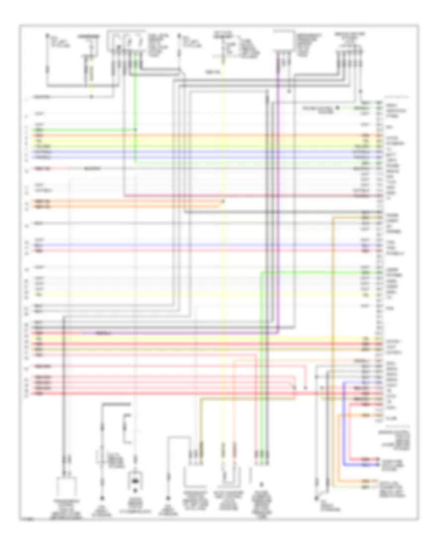
3.5L, Engine Performance Wiring Diagram (4 of 4) for Nissan Maxima GXE 2003
List of elements for 3.5L, Engine Performance Wiring Diagram (4 of 4) for Nissan Maxima GXE 2003:
- (behind center of dash) j/c 20
- 11l
- Aps1
- Aps2
- Ascd b sw
- Avcc
- Avcc2
- B13 (at left "c" pillar)
- Batt
- Can-h
- Can-l
- Cdcv
- Check
- Computer data lines system
- Condenser
- Crankshaft position sensor (pos) (at left side of oil pan)
- Cruise control system
- Data link connector (below left side of dash)
- Engine control module (behind lower center of dash)
- Evap canister vent control valve (on evap canister)
- F39 (front of engine)
- F41 (front of engine)
- F42 (front of engine)
- Fgage+
- Fgage-
- Ftprs
- Fuel level sensor unit & fuel pump (in fuel tank)
- Fuse 15a
- Fuse block (behind left side of dash)
- Gnd-a
- Gnd-a2
- Gnd-e
- Gnd-m
- Hot in on or start
- J/c 18 (behind center of dash)
- Kline
- Knk
- Knock sensor (top of cylinder block)
- Motor 1
- Motor 2
- Nca
- O2sfl
- O2sfr
- O2srl
- O2srr
- Pdpres
- Phase-lh
- Phase-rh
- Pos
- Power steering pressure sensor (on high pressure tube)
- Ps pres
- Qa+
- Qa-
- Red
- Refrigerant pressure sensor (on a/c liquid tank)
- Tps1
- Tps2
- Transmission control module (behind lower center of dash)
- Tvcc
- Vmot
- Vsp-8